F20: Tom & Jerry
Contents
- 1 INTRODUCTION
- 2 ABSTRACT
- 3 OBJECTIVE
- 4 ABOUT THE GAME
- 5 GAME SCREENSHOTS
- 6 TEAM MEMBERS AND RESPONSIBILITIES
- 7 SCHEDULE
- 8 BILL OF MATERIALS
- 9 GAME DESIGN
- 10 IMPLEMENTATION
- 11 PCB DESIGN
- 12 INTEGRATION AND TESTING
- 13 PACKAGING AND ENCLOSURE
- 14 TECHNICAL CHALLENGES AND ADVICE TO FUTURE STUDENTS
- 15 CONCLUSION
- 16 ACKNOWLEDGEMENT
- 17 REFERENCES
- 18 APPENDIX
INTRODUCTION
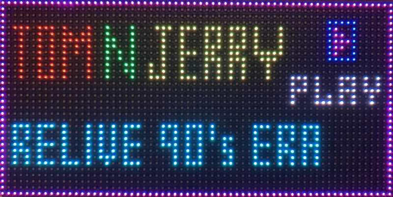
The classic Tom and Jerry cartoons has been a part of our lives since a decade now. Surely, you wouldn't have forgotten their chasings and fun moments inside the house. Play this game and relive the 90's era. The game is designed using RGB LED Matrix and microcontroller LPC 4058.
ABSTRACT
The idea is to relive the childhood days using this game with the characters as Tom and Jerry. Jerry will run inside the maze which will be displayed on the RGB matrix. The route for the mouse will be selected from the pre-defined path at initial state in runtime. Tom (player) will chase this mouse by tilting the board left and right. We are using the SoC accelerometer in SJ2 board for sensing the motion. The cat must catch the mouse before mouse reaches its destination hole. If cat get attracted to drink milk (this is an obstacle), then it must halt for some time, and this will waste it’s time for a while at the same place. The mouse will start running first and then after a delay, the cat will start its motion. The score will be displayed on the LCD which is optional display.
OBJECTIVE
The game objectives are as follows:
- Interfacing the RGB LED Matrix with SJTwo Microcontroller
- Coding simple to use display functions for displaying characters at any given position
- Implement code logic to play three levels for the player to win
- Tasks that can move Tom depending on the user:
- Interrupt to be generated on press of button to start game/Pause the game and switch between displays
- Introduce three lives for Tom
- Have multiple display screens
- MP3 driver for playing multiple audio depending on game stage
ABOUT THE GAME
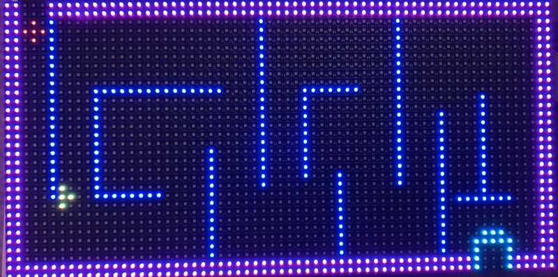
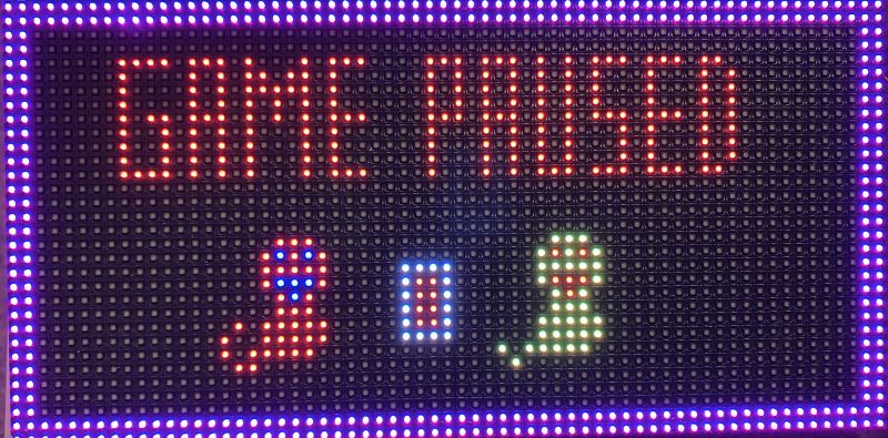
Jerry has yet again successfully annoyed Tom. The whole house has turned into a disrupted maze and Jerry has to run for his life before Tom can catch up with him! Help an annoyed Tom to catch Jerry in this classic cat-vs-mouse maze game! Look out for ways through the maze to catch-up with Jerry before he can reach home.
Additional Features :
- The motive is to catch jerry in the disrupted house before he can reach home.
- Game has Pause and Play feature implemented.
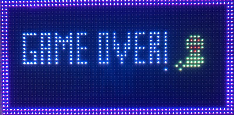
- Tom has 3 lives before he can give up.
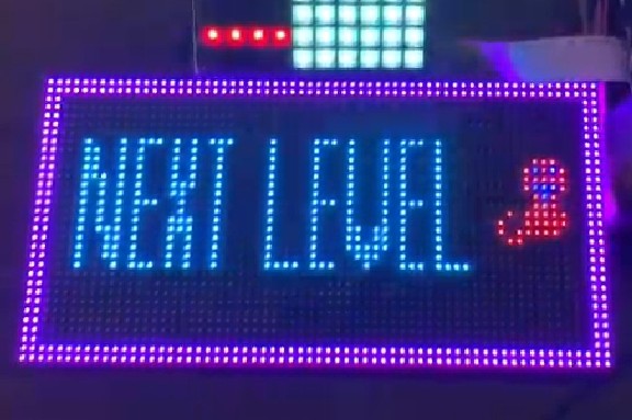
- Every win will take tom to next level.
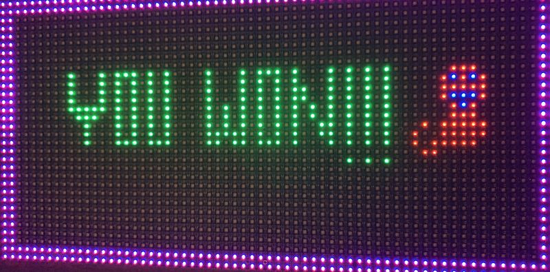
- At the end of third level the player can win the game
- Every stage has its own audio which will give the player a nostalgic feeling of the classic cartoon
GAME SCREENSHOTS
TEAM MEMBERS AND RESPONSIBILITIES
- Sarika Natu
- Developed code for MP3 Decoder Driver to play multiple sounds at various game stages
- Developed Game Architecture
- Developed Game Pause and Play Logic using button interrupts
- Developed Jerry Catch Logic
- Bug fixes on mp3 related FreetRTOS task
- Integrating all the subsystems
- Code Cleanup
- Game Packaging
- Git Repository
- Presentation Slides
- Shivani Pradeep Tambatkar
- Developed code for Accelerometer Driver
- Developed logic for jerry movement
- Developed Maze Design and Game Graphic design
- Developed and finalise game character design
- Developed logic to clear display at every game stage
- PCB Design, Verification and component assembly
- Game Architecture and Testing
- Integrating all the subsystems
- Fixing bugs in overall game architecture
- Game Packaging
- Code Cleanup
- Wiki Page Updates.
- Soumya Sahu
- Developed RGB Matrix driver
- Developed logic for next level and player lives
- Developed logic for collision detection
- Developed logic for smooth Tom movement using accelerometer driver
- Developed Jerry Catch Logic
- Developed initial game character design
- Power Supply Design, PCB Testing and component assembly
- Integrating all the subsystems
- Fixing bugs in overall game architecture
- Game Architecture and Testing
- Code Cleanup
- Game Packaging
- Git Repository
- Finance Manager
SCHEDULE
| Week# | Start Date | End Date | Task | Status |
|---|---|---|---|---|
| 1 |
|
|
|
|
| 2 |
|
|
|
|
| 3 |
|
|
|
|
| 4 |
|
|
|
|
| 5 |
|
|
|
|
| 6 |
|
|
|
|
| 7 |
|
|
|
|
| 8 |
|
|
|
|
| 9 |
|
|
|
|
| 10 |
|
|
|
|
| 11 |
|
|
|
BILL OF MATERIALS
| Part | # | Cost | Source |
|---|---|---|---|
| SJ2 Board | 1 | $50.00 | Preet |
| Sparkfun RGB (32x64) LED Matrix Display | 1 | $65.72 | Amazon |
| PCB Fabrication | 1 | $25.00 | JLC PCB |
| 5V/4A Power Adapter | 1 | $8.99 | Amazon |
| 12v DC Power Jack Adapter Connector | 1 | $3.90 | Amazon |
| Jumper Wires | 1 | $6.99 | Amazon |
| Total Cost | $160.6 |
GAME DESIGN
RGB MATRIX
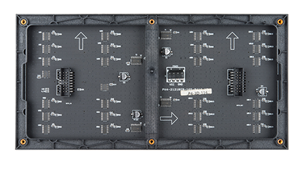
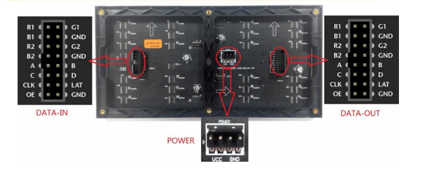
Visuals play huge role in any game design so to achieve this goal we have used 32x64 RGB LED matrix panel. This matrix panel is the heart of the game as no game is complete without graphics. Thorough understanding of the RGB matrix is important to operate the control pins and get the desired output. This section focuses on details related to RGB Matrix and its control ports.
SPECIFICATIONS:
| Pin Number | Pin Name | Pin Function |
|---|---|---|
| 1 | R1 | Upper matrix shift register for red color |
| 2 | G1 | Upper matrix shift register for green color |
| 3 | B1 | Upper matrix shift register for blue color |
| 4 | R2 | Lower matrix shift register for red color |
| 5 | G2 | Lower matrix shift register for green color |
| 6 | B2 | Lower matrix shift register for blue color |
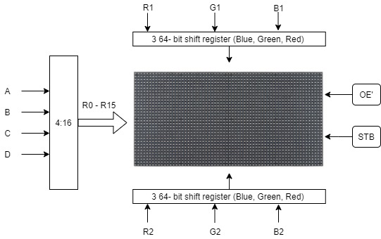
| 7 | A | Row selection mux |
| 8 | B | Row selection mux |
| 9 | C | Row selection mux |
| 10 | D | Row selection mux |
| 10 | E | This pin is ground |
| 12 | Clock | Clock in data into the shift registers |
| 13 | Latch | Latch the values in RGB shift registers |
| 14 | Output Enable (OE) | Display the shift register values on the RGB matrix panel |
| 15 | Ground | Ground |
| 16 | Ground | Ground |
| D | C | B | A | Row Selected |
|---|---|---|---|---|
| 0 | 0 | 0 | 0 | 0 |
| 0 | 0 | 0 | 1 | 1 |
| 0 | 0 | 1 | 0 | 2 |
| 0 | 0 | 1 | 1 | 3 |
| 0 | 1 | 0 | 0 | 4 |
| 0 | 1 | 0 | 1 | 5 |
| 0 | 1 | 1 | 0 | 6 |
| 0 | 1 | 1 | 1 | 7 |
| 1 | 0 | 0 | 0 | 8 |
| 1 | 0 | 0 | 1 | 9 |
| 1 | 0 | 1 | 0 | 10 |
| 1 | 1 | 0 | 1 | 11 |
| 1 | 1 | 0 | 0 | 12 |
| 1 | 1 | 0 | 1 | 13 |
| 1 | 1 | 1 | 0 | 14 |
| 1 | 1 | 1 | 1 | 15 |
Hardware Interface
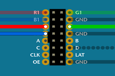
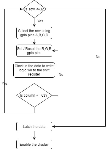
The 32x64 RGB matrix panel is divided into two horizontal sections i.e. 2 16x64 RGB matrix. The upper matrix LEDs are individually accessible, and each LED can display 3 primary colors RED, BLUE, GREEN. The combination of these three primary colors can give access to CYAN, YELLOW,PINK, WHITE colors. The control pins A, B,C, D act as multiplexer of 4:16. Using this concept one can access 1 pixel of upper (R1,G1,B1) and lower matrix (R2,G2,B2) simultaneously. The RGB control pin are shift registers of size equivalent to the width of the RGB matrix panel. In our case, there are 64 columns and therefore, the shift register can store 64-bit data. The bits are fed into this shift register bit-by-bit using the clock pin present in the RGB connection port. The data is shifted for every clock pulse i.e. every time when the clock pulse shifts from logic 0 to logic 1 or vice versa. Once all the bits are present in this shift register, the LAT pin is set to high and the register values are latched to display on the panel. Now, OE pin (active low) is set low to display the combination on the matrix. We will need DATA_IN only if we are using 1 matrix panel.
| RGB LED PINS | SJ2PINS |
|---|---|
| R1 | P2.0 |
| G1 | P2.1 |
| B1 | P2.2 |
| R2 | P2.5 |
| G2 | P2.4 |
| B2 | P0.15 |
| A | P2.7 |
| B | P2.8 |
| C | P2.9 |
| D | P0.16 |
| Latch | P1.23 |
| Output Enable (OE) | P1.20 |
| Clock | P1.28 |
Software Interface
This flowchart is a well-defined workflow to operate an RGB matrix. To avoid any flickering or ghosting of the pixels, the OE pin needs to be paid an extra attention.
MP3 Decoder
Hardware Interface
Accelerometer
HW Interface
SW Interface
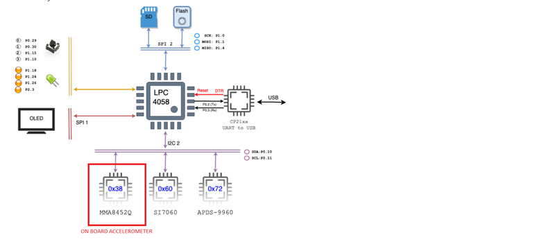
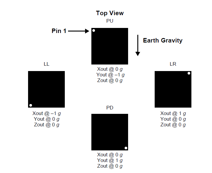
We have worked on accelerometer sensor to control the motion of Tom(Player). The SJ-Two board has this sensors on board sensor which is interfaced on the I2C bus. Accelerometers are electromechanical devices that sense either static or dynamic forces of acceleration. Static forces include gravity, while dynamic forces can include vibrations and movement. The measurements are on 3-axis and these values can be calibrated to find the desired values. In our project, an accelerometer is for controlling the movement of Tom in all 4 directions i.e. Left, Right, Up and Down. The following set of registers were used to set and detect the orientation.
Orientation Detection
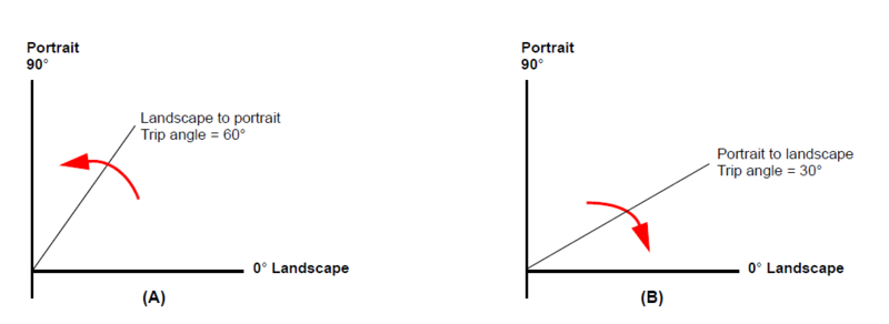
The MMA8452Q has an orientation detection algorithm with the ability to detect all six orientations. The transition from portrait to landscape is fixed with a 45° threshold angle and a ±14° hysteresis angle. This allows the for a smooth transition from portrait to landscape at approximately 30° and then from landscape to portrait at approximately 60°. The angle at which the device no longer detects the orientation change is referred to as the Z-lockout angle. The device operates down to 29° from the flat position. All angles are accurate to ±2°.
Game Logic
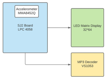
- Block Diagram
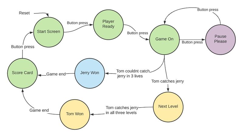
- Game states
IMPLEMENTATION
MP3 DECODER
Psuedo code for reading the music
- Each game state has its corresponding mp3 music
- Sound flags are checked to find the game state
- Find the respective file
- Open the mp3 file
- Read the contents of the file by protecting it with a mutex
- Send the data over queue to the play task
  if ((sound.scorecard) && (current_state != SCORECARD)) {
     result = f_close(&file);
     result = f_findfirst(&dj, &fno, "", "5.mp3");
     result = f_open(&file, fno.fname, FA_OPEN_EXISTING | FA_READ);
     sound.scorecard = false;
     current_state = SCORECARD;
   }
   else if ((sound.catchfail) && (current_state != CATCHFAIL)) {
     result = f_close(&file);
     result = f_findfirst(&dj, &fno, "", "4.mp3");
     result = f_open(&file, fno.fname, FA_OPEN_EXISTING | FA_READ);
     sound.catchfail = false;
     current_state = CATCHFAIL;
   }
   else if ((sound.catchsuccess) && (current_state != CATCHSUCCESS)) {
     result = f_close(&file);
     result = f_findfirst(&dj, &fno, "", "3.mp3");
     result = f_open(&file, fno.fname, FA_OPEN_EXISTING | FA_READ);
     sound.catchsuccess = false;
     current_state = CATCHSUCCESS;
   }
   else if ((sound.game) && (current_state != GAME)) {
     result = f_close(&file);
     result = f_findfirst(&dj, &fno, "", "2.mp3");
     result = f_open(&file, fno.fname, FA_OPEN_EXISTING | FA_READ);
     sound.game = false;
     current_state = GAME;
   }
   else if ((sound.entry) && (current_state != DEFAULT)) {
     result = f_close(&file);
     result = f_findfirst(&dj, &fno, "", "1.mp3");
     result = f_open(&file, fno.fname, FA_OPEN_EXISTING | FA_READ);
     sound.entry = false;
     current_state = DEFAULT;
   }
   xSemaphoreTake(mp3_mutex, portMAX_DELAY);
   result = f_read(&file, &bytes_to_read[0], READ_BYTES_FROM_FILE, &bytes_read);
   }
   xSemaphoreGive(mp3_mutex);
   xQueueSend(mp3_queue, &bytes_to_read[0], portMAX_DELAY);
Psuedo code for playing the music
- Mp3 data is received over the queue
- Mp3 data is send to the decoder by keeping a counter of 32 bytes and incrementing it for each cycle till complete data is sent.
- The shared resource which is mp3 data is protected using the mutex, which is further send to the decoder using SPI
static uint8_t bytes_to_read[READ_BYTES_FROM_FILE];
 static uint8_t current_count = 0;
 uint32_t start_index = 0;
 while (1) {
   if (current_count == 0) {
     xQueueReceive(mp3_queue, &bytes_to_read[0], portMAX_DELAY);
   }
   start_index = (current_count * MAX_BYTES_TX);
   while (!mp3_dreq_get_status()) {
     vTaskDelay(2);
   }
   if (xSemaphoreTake(mp3_mutex, portMAX_DELAY)) {
     send_bytes_to_decoder(start_index, &bytes_to_read[0]);
     xSemaphoreGive(mp3_mutex);
     if (current_count == (READ_BYTES_FROM_FILE / MAX_BYTES_TX) - 1) {
       current_count = 0;
     } else {
       current_count += 1;
     }
   }
 }
RGB MATRIX
Software Interface
 for (uint8_t row = 0; row < LEDMATRIX_HALF_HEIGHT; row++) {
     disable_display();
     disable_latch_data();
     select_row(row);
     data_clock_in(row);
     enable_latch_data();
     enable_display();
     delay__us(150);
     disable_display();
   }
     disable_display();
   }
Jerry Movement
The Jerry start movement is independent of any other FreeRTOS task. Jerry who is running on a 32 x 64 Matrix table activates 4 pixels at the same time and to show the movement of jerry, it is important to clear the previous pixels. The 4 pixels that are activated in the matrix is exactly where the Tom can find jerry and catch it. Tom and Jerry are running on the same x-y plane 32 x 64 matrix. The motion of Jerry is fixed in the program, but Tom is unaware of Jerry’s route and therefore Tom can only try to catch Jerry by running after it , or by playing smart! The player (Tom) needs to analyze the maze so that it can catch Jerry by fooling it.
 for (jerry_motion_counter = JERRY_START_POSITION;
      jerry_motion_counter <= jerry_end_positions[level];
      jerry_motion_counter++) {
   for (uint8_t y = 0; y < LEDMATRIX_WIDTH; y++) {
     for (uint8_t x = 0; x < LEDMATRIX_HEIGHT; x++) {
  {
         if (maze_one_lookup_table[x][y] == jerry_motion_counter) {
           jerry.x = x;
           jerry.y = y;
           set_pixel(x, y, YELLOW);         // top
           set_pixel(x + 2, y, YELLOW);     // bottom
           set_pixel(x + 1, y, YELLOW);     // middle_left
           set_pixel(x + 1, y + 1, YELLOW); // middle_right
           delay__ms(150);
           clear_pixel(x, y);
           clear_pixel(x + 2, y);
           clear_pixel(x + 1, y);
           clear_pixel(x + 1, y + 1);
         }
       }
     }
   }
  }
 }
Tom Movement
The movement of Tom is dependent on the output from the Accelerometer sensor. We have taken Up, down, left and right motions into count to move Tom in maze. Every Tom moves right , then the horizontal motion counter increments and when it goes to left, the horizontal motion counter decrements. Similarly, when Tom moves up, the vertical motion is incremented, and it decrements when Tom moves down. Boundary conditions are used to restrict Tom from moving out of boundary or crossing any walls.
 void tom_image(uint8_t vertical_motion, uint8_t horizontal_motion) {
 tom.vertical_motion = vertical_motion;
 tom.horizontal_moiton = horizontal_motion;
 set_pixel(x + 1, y + 2, RED); // top
 set_pixel(x + 2, y + 1, RED); // left
 set_pixel(x + 2, y + 2, RED); // middle
 set_pixel(x + 2, y + 3, RED); // right
 set_pixel(x + 3, y + 2, RED); // bottom
 delay__ms(1);
 clear_pixel(x + 1, y + 2);
 clear_pixel(x + 2, y + 1);
 clear_pixel(x + 2, y + 2);
 clear_pixel(x + 2, y + 3);
 clear_pixel(x + 3, y + 2);
 }
Collision Detection
The game gets exciting when Tom is after Jerry. Jerry being cunning mouse tries to fool Tom by changing path, but Tom is focused to win the title of the best BEST CAT! In the game software, the current coordinates of Tom and Jerry are stored and is continuously compared. When the pixel of Tom clashes with any pixel of Jerry, the collision is detected. All the pixels of Tom image and Jerry image are active and therefore any image pixel collision will be detected by the function collision_detector.
 static void collision_detector(void) {
 if ((jerry.x == tom.x + 3 && jerry.y == tom.y + 2) ||
     (jerry.x + 1 == tom.x + 3 && jerry.y + 1 == tom.y + 2) ||
     (jerry.x + 2 == tom.x + 3 && jerry.y == tom.y + 2) ||
     (jerry.x + 1 == tom.x + 3 && jerry.y == tom.y + 2)) {
   game_screen_state = TOM_WON;
   clear_screen_display();
 } else if ((jerry.x == tom.x + 2 && jerry.y == tom.y + 3) ||
            (jerry.x + 1 == tom.x + 2 && jerry.y + 1 == tom.y + 3) ||
            (jerry.x + 2 == tom.x + 2 && jerry.y == tom.y + 3) ||
            (jerry.x + 1 == tom.x + 2 && jerry.y == tom.y + 3)) {
   game_screen_state = TOM_WON;
   clear_screen_display();
 } else if ((jerry.x == tom.x + 2 && jerry.y == tom.y + 1) ||
            (jerry.x + 1 == tom.x + 2 && jerry.y + 1 == tom.y + 1) ||
            (jerry.x + 2 == tom.x + 2 && jerry.y == tom.y + 1) ||
            (jerry.x + 1 == tom.x + 2 && jerry.y == tom.y + 1)) {
   game_screen_state = TOM_WON;
   clear_screen_display();
 } else if ((jerry.x == tom.x + 1 && jerry.y == tom.y + 2) ||
            (jerry.x + 1 == tom.x + 1 && jerry.y + 1 == tom.y + 2) ||
            (jerry.x + 2 == tom.x + 1 && jerry.y == tom.y + 2) ||
            (jerry.x + 1 == tom.x + 1 && jerry.y == tom.y + 2)) {
   game_screen_state = TOM_WON;
   clear_screen_display();
 }
 }
ACCELEROMETER
- Pseudo Code:
- Set the acceleration to Standby mode before enabling orientation.
- Enabling orientation involves setting the orientation detection bit in Config register and then setting the debounce counter.
- Only after performing step 2 can the acceleration be set to active mode along with the data transfer rate. In our project we have set that to 50Hz.
- In order to detect the orientation, the Status register bits are monitored for the orientation you want.
- Finally after receiving the above data, action can be performed as shown in below snippet.
 void action_on_orientation(void *p) {
   orientation_e value;
   while (1) {
   value = acceleration_get_data();
   switch (value) {
   case Landscape_LEFT:
     command_left = true;
     if (left_move) {
       left_movement();
     }
     left_move = true;
     break;
   case Landscape_RIGHT:
     command_right = true;
     if (right_move) {
       right_movement();
     }
     right_move = true;
     break;
   case Portrait_DOWN:
     command_down = true;
     if (down_move) {
       down_movement();
     }
     down_move = true;
     break;
   default:
     command_up = true;
     if (up_move) {
       up_movement();
     }
     up_move = true;
     break;
   }
   vTaskDelay(100);
   tom_move_on_maze(row_count, col_count);
 }
 }
PCB DESIGN
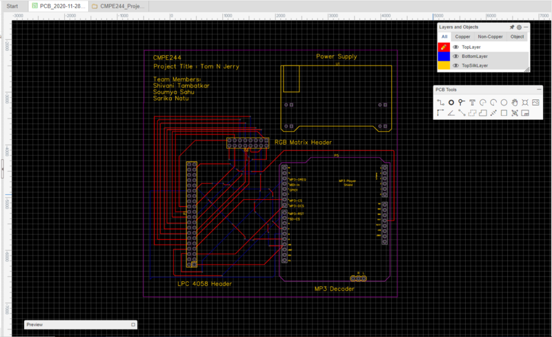
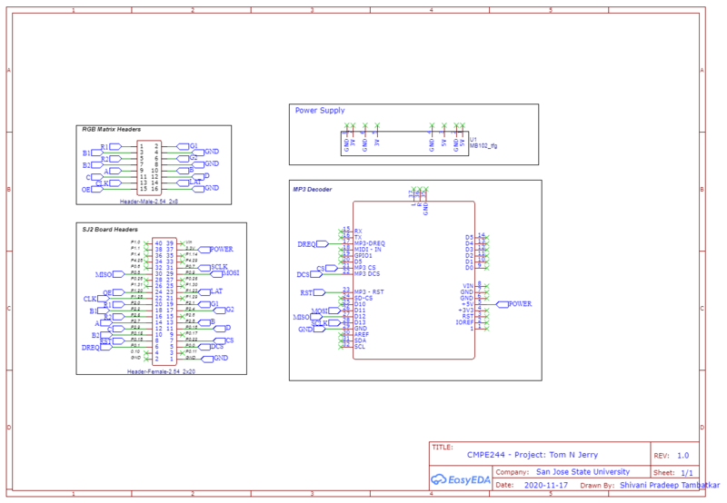
We have designed and developed a PCB in order to supply power for SJTwo board and RGB LED Matrix which is able to provide 5V supply efficiently. The PCB Layout is designed using the Easy EDA Online Software Tool. The Power Supply circuit board used contains IC7805 voltage regulator IC and a voltage divider to fulfill the specific power requirements. IC7805 is a linear voltage regulator which has a variable output voltage ranging from 4.8 V to 5.2 V and is suitable for our application. We have used a 5V adapter in order to power our board. This serves for both the current requirements.
Fabrication
PCB was sent to fabrication to JLCPCB China which provided PCB with MOQ 2 layers of PCB.
DRC elements (in mils):
- Track Width = 12
- Clearance = 10
- Via Diameter = 24
INTEGRATION AND TESTING
PACKAGING AND ENCLOSURE
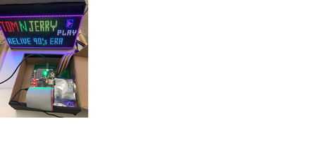
The packaging for the final product was done using set of cardboard boxes since due to pandemic we did not have access to 3D printer on college premises.
TECHNICAL CHALLENGES AND ADVICE TO FUTURE STUDENTS
LED Matrix
- The OE pin when low, it switches off the LEDs before transition to next row) and LAT (when high) it latches the output pin with current row value). Before transitioning new row value it is important to follow the above instructions, otherwise you will see ghosting effect in the LEDs.
- The datasheet provided by Sparkfun is insufficient to understand the working of the RGB Matrix. Therefore, lot of time was spent in understanding the working of the matrix. One must understand the hardware connections well, the RGB matrix ribbon has a red line strip at the top so use this red color as the reference during the connections. During development and testing, try to use jumper wires of the color of RGB, follow the color code to avoid any confusion.
- Since all the tasks are updating the pixel values continuously therefore give the RGB update task the highest priority to see an immediate change in the Matrix.
- Setting the right delay for the image movement is important otherwise the image will not appear, or the older pixels will not clear simultaneously.
- The toughest part is synchronizing the movement of both Tom and Jerry together.
PCB
- Auto-routing gave lot of challenges and sometimes the wires are barely connected which throws DRC errors very frequently. Even local routing had lot of issues. So design requires careful attention and time.
- The PCB went through a lot of internal revisions even before placing order which was time-consuming.
MP3 DECODER
- Implementing multiple songs for different stages. Embedding multiple sounds for every stage was very time consuming . Also the Game on mode could not have any sound as it was interfereing in the movement of the characters. This task should be given higher priority along to avoid delay and noise.
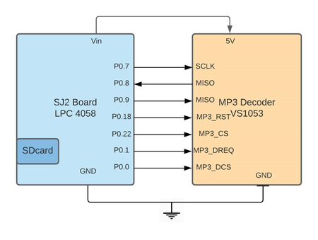
- Earlier we used the ssp2 Driver written by Preet for SPI interfacing to write the data to MP3 Decoder. but somehow we were not able to detect the slave properly because of which we could not communicate with the decoder. Hence we wrote our own simple SPI driver which sends the data to the MP3 Decoder for playing the music in background.
GRAPHIC DISPLAY
- We had hard time in choosing the design for the characters as the circular design was consuming more pixels which was not helping the maze design. Hence we settled for a simple design which occupied lesser pixels and left more space for the cxharacters.
ACCELEROMETER
- In the Accelerometer PL_STATUS register, while trying to monitor the orientation we were monitoring the NEWLP. But this bit is set and cleared even before an I2C read can happen. Hence if this is used in a conditional statement then the code will never detect any orientation even though there is movement. Its best not to moinitor these bits and jump directly to monitoring other PL_STATUS bits.
PACKAGING
- Initially we decided on different packaging, however we couldn’t do that due to oandemic which did not allow us access to 3D printer and accelerometer orientation issue and ribbon issue. The ribbon was too small and hence it was difficult to move the controller freely. It is advasable for furture students to use a longer ribbon or switch to a joystick
CONCLUSION
Conclude your project here. You can recap your testing and problems. You should address the "so what" part here to indicate what you ultimately learnt from this project. How has this project increased your knowledge?
ACKNOWLEDGEMENT
We would like to express our gratitude to Professor Preetpal Kang for his guidance throughout the semester and providing us with this opportunity. We would also like to thank the TA Vidhushi Jain for being available whenever in need and guiding us to complete the project.
REFERENCES
- FreeRTOS documentations
- Adafruit Github Library
- WikiPage by Preetpal Kang
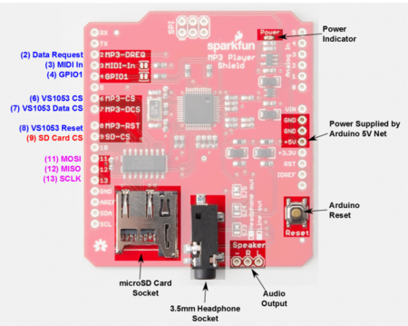
- Sparkfun MP3 Decoder
- Design Tool:EasyEDA

