F20: Treasure Diver
Contents
- 1 Treasure Diver
- 2 Abstract
- 3 Objectives
- 4 Introduction
- 5 Schedule
- 6 Parts List & Cost
- 7 Design & Implementation
- 8 Technical Challenges
- 9 Advice for Future Students
- 10 Conclusion
- 11 References
Treasure Diver
Abstract
Treasure Diver is a single player game in which the player descends into watery depths on the hunt for treasure. The player must dodge obstacles and enemy creatures all while collecting treasure along the way. While descending the player is able to attack enemies at a range which in turn may give them power ups such as extra air, faster move speed, or temporary invincibility. When they reach the bottom they can collect the Motherlode. After that they have to ascend the cavern and make it out with all their treasure in one piece. Hitting an enemy or obstacle causes the player to lose air and a treasure chest and when their air hits zero it’s game over. At the end of a level the player is given a score based on treasure collected, remaining air, and the amount of enemies destroyed.
Objectives
Show list of your objectives. This section includes the high level details of your project. You can write about the various sensors or peripherals you used to get your project completed.
Introduction
Team Members & Responsibilities
Treasure Diver GitLab
- Ameer Ali GitLab LinkedIn
- LED Matrix Driver
- Matrix Graphics Development
- Game Logic Development
- Gameplay Design
- Wiki Page Management
- Jesus De Haro GitLab LinkedIn
- Game Pad Controller
- MP3 Decoder Driver
- Matrix Graphics Development
- PCB Design
- GitLab Repo Management
- Nicholas Kaiser GitLab LinkedIn
- HC05 Bluetooth Driver and Interface
- Matrix Collision Detection Development
- CAD Enclosure Design
- PCB Design
- Wiki Page Management
Schedule
| Week # | Start Date | End Date | Task | Status |
|---|---|---|---|---|
| 1 | 9/27/2020 | 10/3/2020 |
|
|
| 2 | 10/4/2020 | 10/10/2020 |
|
|
| 3 | 10/11/2020 | 10/17/2020 |
|
|
| 4 | 10/18/2020 | 10/24/2020 |
|
|
| 5 | 10/25/2020 | 10/31/2020 |
|
|
| 6 | 11/1/2020 | 11/7/2020 |
|
|
| 7 | 11/8/2020 | 11/14/2020 |
|
|
| 8 | 11/15/2020 | 11/21/2020 |
|
|
| 9 | 11/22/2020 | 11/28/2020 |
|
|
| 10 | 11/29/2020 | 12/5/2020 |
|
|
| 11 | 12/6/2020 | 12/12/2020 |
|
|
| 12 | 12/13/2020 | 12/19/2020 |
|
|
Parts List & Cost
Give a simple list of the cost of your project broken down by components. Do not write long stories here.
Design & Implementation
Insert diagram of all modules connected to each sj2 board (using pictures of actual modules)
PCB Design
Brief description. Insert PCB schematics and pictures of actual pcbs
CAD Enclosures Design
Brief description. Insert CAD design screenshots and pics of actual enclosures
RGB LED Matrix
Brief description of what this module does. Insert diagram of led matrix connected to sj2 (using pictures of actual modules)
Hardware Design
Discuss your hardware design here. Show detailed schematics, and the interface here. In this section, you can describe how your hardware communicates, such as which BUSes used. You can discuss your driver implementation here, such that the Software Design section is isolated to talk about high level workings rather than inner working of your project.
Software Design
Use a flowchart(s)
Implementation
Short code snippets or pseudo-code with explanations
MP3 Decoder
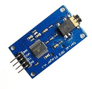
The YX5300 MP3 Music Player Module is used in the project to play music at the menu, gameplay and at the Victory/Gameover screen. Although we use it to decode MP3 files, it can also decode MAV files. This board contains a slot for SD card mounting, which we command the module to read from. Insert diagram of MP3 decoder connected to sj2 (using pictures of actual modules)
Hardware Design
This module is easy to interface since it only uses UART pins (Rx and Tx), excluding the Vcc and Ground. This board was able to be powered with the 3.3V power from the SJ2 board. The MP3 decoder was connected to 2 SJ2 pins....(to be continued). Discuss your hardware design here. Show detailed schematics, and the interface here. In this section, you can describe how your hardware communicates, such as which BUSes used. You can discuss your driver implementation here, such that the Software Design section is isolated to talk about high level workings rather than inner working of your project.
Software Design
For ease of code reading, memory was unionized so it may be accessed as an array and by variable names that correspond to the command packet format that is specified in the module's datasheet. Use a flowchart(s)
Implementation
The datasheet specifies the command packet to the MP3 decoder to be a minimum size of 8 bytes composed of the START, VERSION, LENGTH, COMMAND, FEEDBACK, DATA (min of 2 bytes), and END bytes. To make the implementation self explanatory and easy to use (via array), the commands were placed in a unionized memory location (shown below). This approach made it easier
typedef struct {
  uint8_t bytes[8]; ///< 8 bytes of a mp3 decoder message
} mp3_decoder__command_t;

typedef union {
  mp3_decoder__command_t decoder_command; ///< 64-bit command message to decoder
  struct {
    uint64_t start_byte : 8;    // Will be set to 0x7E
    uint64_t version_byte : 8;  // Will be set to 0xFF
    uint64_t data_length : 8;   // Will be set to 0x06
    uint64_t command_byte : 8;  // Varies
    uint64_t feedback_byte : 8; // Will be set to 0x00
    uint64_t data_byte0 : 8;    // Varies
    uint64_t data_byte1 : 8;    // Varies
    uint64_t end_byte : 8;      // Will be set to 0xxEF
  } decoder_command_byte;
} mp3_decoder__msg_t;
The commands were structured as an enum for dedicated functions to use in setting command_byte in the command packet via decoder_command_byte members. Once the command is set, the packet is accessed as an array to simplify sending over UART.
Bluetooth Interface
Brief description of what this module does. Insert diagram of bluetooth connected to each sj2 (using pictures of actual modules)
Hardware Design
Discuss your hardware design here. Show detailed schematics, and the interface here. In this section, you can describe how your hardware communicates, such as which BUSes used. You can discuss your driver implementation here, such that the Software Design section is isolated to talk about high level workings rather than inner working of your project.
Software Design
Use a flowchart(s)
Implementation
(Short code snippets or pseudo-code with explanations)
Game Pad Controller
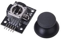
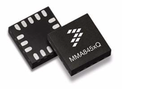
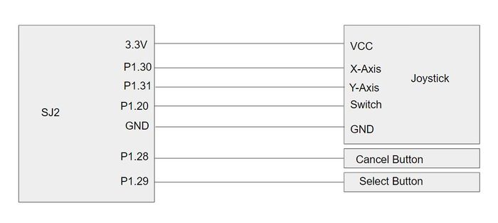
Brief description of what this module does. Insert diagram of joystick and buttons connected to sj2 (using pictures of actual modules) The main components in Game Pad controller are a joystick, accelerometer, two buttons, and bluetooth. The controller is used to send commands and control Steve (the main character) in Treasure Diver, along with navigation of the menus, with the joystick or the SJ2's on-board accelerometer (user's choice). With bluetooth on the game pad, the controller is wireless.
Hardware Design
Discuss your hardware design here. Show detailed schematics, and the interface here. In this section, you can describe how your hardware communicates, such as which BUSes used. You can discuss your driver implementation here, such that the Software Design section is isolated to talk about high level workings rather than inner working of your project.
Software Design
Use a flowchart(s)
Implementation
Short code snippets or pseudo-code with explanations
Technical Challenges
Describe the challenges of your project. What advise would you give yourself or someone else if your project can be started from scratch again? Make a smooth transition to testing section and described what it took to test your project.
Include sub-sections that list out a problem and solution, such as:
CAD Enclosures Design
- Discuss issue and resolution 1.
- Discuss issue and resolution 2.
- Discuss issue and resolution n.
PCB Design
- Discuss issue and resolution 1.
- Discuss issue and resolution 2.
- Discuss issue and resolution n.
LED Matrix
- Discuss issue and resolution 1.
- Discuss issue and resolution 2.
- Discuss issue and resolution n.
MP3 Decoder
- The datasheet lacks some information and clarity on initializing the module and with some of the commands. When first using it, non of the commands appeared to work or have any effect. The issue was resolved after sending the command to select a device, which was not explicitly stated in the datasheet. Once this command is first sent, the MP3 decoder now begins accepting commands.
- Discuss issue and resolution 2.
- Discuss issue and resolution n.
Bluetooth Interface
- Discuss issue and resolution 1.
- Discuss issue and resolution 2.
- Discuss issue and resolution n.
Game Pad Controller
- Discuss issue and resolution 1.
- Discuss issue and resolution 2.
- Discuss issue and resolution n.
Advice for Future Students
CAD Enclosures Design
- Advice/tip #1
- Advice/tip #2
- Advice/tip #n
PCB Design
- Use EasyEDA to design your PCBs. It has an auto-routing feature so you don't have to perform any routing by hand which saves you so much time. It also automatically converts your schematic to components that you just "drag and drop" onto your PCB while the connections are automatically maintained.
- Order your PCBs from JLCPCB (integrated into EasyEDA). You'll get them in 1 week.
- In EasyEDA, may sure you check the connections for each footprint you're using. Sometimes the footprint's pinout won't exactly match your schematic.
- Advice/tip #n
LED Matrix
- Advice/tip #1
- Advice/tip #2
- Advice/tip #n
MP3 Decoder
- Advice/tip #1
- Advice/tip #2
- Advice/tip #n
Bluetooth Interface
- Advice/tip #1
- Advice/tip #2
- Advice/tip #n
Game Pad Controller
- Advice/tip #1
- Advice/tip #2
- Advice/tip #n
General
- Advice/tip #1
- Advice/tip #2
- Advice/tip #n
Conclusion
Conclude your project here. You can recap your testing and problems. You should address the "so what" part here to indicate what you ultimately learnt from this project. How has this project increased your knowledge?
Project Video
Project Source Code
References
Acknowledgement
Any acknowledgement that you may wish to provide can be included here.
References Used
List any references used in project.
Appendix
You can list the references you used.


