S20: Tesla Model RC
Contents
Tesla Model RC
Abstract
Tesla Model RC is an electric, battery-powered, self-navigating RC car. The aim is to navigate to the destination set on the Android application by utilizing GPS navigation. The car combines the data received from multiple sensors to perceive its surroundings to avoid obstacles in its path.
Introduction
The project was divided into N modules:
- Sensor ...
- Motor..
- ...
- Android
Team Members & Responsibilities
<Team Picture>
- Git Project Link: Tesla Model RC
Roles to be determined
- Salvatore Nicosia Salvatore Nicosia
- Nickolas Schiffer Nickolas Schiffer
- Ayesha Siddiqua Ayesha Siddiqua
- Zainab Khan Zainab Khan
- Danny Nuch Danny Nuch
- Andrew Kwon Andrew Kwon
- Sensor
- Link to Gitlab user1
- Link to Gitlab user2
- Motor
- Link to Gitlab user1
- Link to Gitlab user2
- Geographical
- Link to Gitlab user1
- Link to Gitlab user2
- Communication Bridge Controller & LCD
- Link to Gitlab user1
- Link to Gitlab user2
- Android Application
- Link to Gitlab user1
- Link to Gitlab user2
- Testing Team
- Link to Gitlab user1
- Link to Gitlab user2
Schedule
| Week# | Start Date | End Date | Task | Status |
|---|---|---|---|---|
| 1 |
|
|
|
In Progress |
| 2 |
|
|
|
TODO |
| 3 |
|
|
|
TODO |
| 4 |
|
|
|
TODO |
| 5 |
|
|
|
TODO |
| 6 |
|
|
|
TODO |
| 7-11 |
|
|
|
TODO |
Parts List & Cost
| Item# | Part Desciption | Vendor | Qty | Cost |
|---|---|---|---|---|
| 1 | RC Car | Traxxas | 1 | $250.00 |
| 2 | CAN Transceivers MCP2551-I/P | Microchip [1] | 8 | Free Samples |
Printed Circuit Board
<Picture and information, including links to your PCB>
CAN Communication
<Talk about your message IDs or communication strategy, such as periodic transmission, MIA management etc.>
Hardware Design
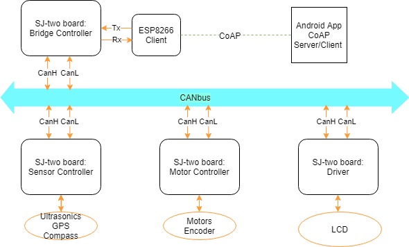
<Show your CAN bus hardware design> High Level Hardware Diagram
DBC File
<Gitlab link to your DBC file> <You can optionally use an inline image>
Sensor ECU
<Picture and link to Gitlab>
Hardware Design
Software Design
<List the code modules that are being called periodically.>
Technical Challenges
< List of problems and their detailed resolutions>
Motor ECU
<Picture and link to Gitlab>
Hardware Design
Software Design
<List the code modules that are being called periodically.>
Technical Challenges
< List of problems and their detailed resolutions>
Geographical Controller
<Picture and link to Gitlab>
Hardware Design
Software Design
<List the code modules that are being called periodically.>
Technical Challenges
< List of problems and their detailed resolutions>
Communication Bridge Controller & LCD
<Picture and link to Gitlab>
Hardware Design
Software Design
<List the code modules that are being called periodically.>
Technical Challenges
< List of problems and their detailed resolutions>
Master Module
<Picture and link to Gitlab>
Hardware Design
Software Design
<List the code modules that are being called periodically.>
Technical Challenges
< List of problems and their detailed resolutions>
Mobile Application
<Picture and link to Gitlab>
Hardware Design
Software Design
<List the code modules that are being called periodically.>
Technical Challenges
< List of problems and their detailed resolutions>
Conclusion
<Organized summary of the project>
<What did you learn?>
Project Video
Project Source Code
Advise for Future Students
<Bullet points and discussion>
