F19: Alien Wars
Contents
Alien Wars
Abstract
Alien wars is a single player combat game, with increasing levels of difficulty. Each level has a has target number of enemy spaceships to be destroyed, before the ultimate villain ‘the alien king’ appears. Once the ultimate villain is killed the player proceeds to next level. The speed of the enemy spaceships approaching the player will increase with the increasing levels. The player can choose to either shoot the enemy spaceship using missiles or dodge it. The game ends when the player crashes with enemy spaceship.
Objectives & Introduction
Objectives
- Write drivers to display game characters and update the display continuously.
- Write drivers to give directions from the input devices (joystick)
- Write drivers to transmit control signals wirelessly via Bluetooth
- Write drivers to play game sounds via MP3 encoder
- Implement game algorithm for movement of player and enemy spaceships in real-time, generate bullets.
- Implement spaceship, health and bullet collision algorithm
- Use FreeRTOS tasks and understand task priority and synchronization.
Game User guide
- 1- player arcade game.
- 3-levels to reach victory.
- Press switch on the joystick to start.
- Movement of joystick controls the movement of spaceship
- Press switch on joystick will now shoot bullets
- Game advances as the spaceship kills certain enemy spaceships
- The speed of the enemy spaceship increases in the second level
- In the final level, the user spaceship faces the villain, user spaceship has to face the bullets from villain as well.
- User spaceship has to survive the bullets and fire the enemy. After taking few hits, villain dies and its victory!
- Throughout the game when the user spaceship collides with enemy or bullet, its health decreases, the color of the spaceship also changes. The game is over when player health is zero.
Team Members & Responsibilities
- Abhinandan Burli
- Developing enemy game algorithm
- Developing game characters on LED matrix display
- GPIO driver for LED matrix display
- Joel Samson
- Joystick interfacing - ADC driver
- Bluetooth Interfacing - UART driver for transmitter & receiver
- Game Animation Screens
- Basangouda Patil
- Speaker and MP3 encoder interfacing
- GPIO driver for LED matrix displays
- Bug fixes and optimizations
Schedule
| Week# | Date | Task | Status | Actual Completion Date |
|---|---|---|---|---|
| 1 | 10/01/2019 |
|
|
|
| 2 | 10/08/2019 |
|
|
|
| 3 | 10/15/2019 |
|
|
|
| 4 | 10/22/2019 |
|
|
|
| 5 | 10/29/2019 |
|
|
|
| 6 | 11/05/2019 |
|
|
|
| 7 | 11/12/2019 |
|
|
|
| 8 | 11/19/2019 |
|
|
|
| 9 | 11/26/2019 |
|
|
|
| 10 | 12/03/2019 |
|
|
|
| 11 | 12/10/2019 |
|
|
|
| 12 | 12/17/2019 |
|
|
|
Parts List & Cost
| Item# | Part Desciption | Vendor | Qty | Cost |
|---|---|---|---|---|
| 1 | SJTwo Boards | From Preet | 3 | $150.00 |
| 2 | 32x64 RGB LED Matrix | Adafruit | 1 | $92.00 |
| 3 | Wiring Components and Cable | Amazon | 1 | $20 |
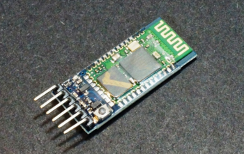
| 4 | HC05 Bluetooth module | Amazon | 2 | $35 |
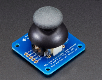
| 5 | Adafruit Analog 2-axis thumb Joystick | Adafruit | 1 | $9 |
| 6 | MP3 music player (YX5300) | Amazon | 1 | $8 |
Design & Implementation
Hardware Design
Discuss your hardware design here. Show detailed schematics, and the interface here.
Hardware Interface
In this section, you can describe how your hardware communicates, such as which BUSes used. You can discuss your driver implementation here, such that the Software Design section is isolated to talk about high level workings rather than inner working of your project.
Software Design and Implementation
Bluetooth Implementation (Master & Slave)
Two HC05 Bluetooth modules were used. One was configured as the master using AT commands and the second module as slave. The baud rate for communication was set at 38400. The Master Bluetooth module was interfaced to the player joystick SJ2 board. The slave Bluetooth was interfaced to the main SJ2 board connected to the LED Matrix display. UART3 was used (Tx and Rx) for communication between the micro controller and HC05 Bluetooth module. On the transmitter side based on the analog joystick input, the enum value corresponding to that particular direction is sent. Based on the value received from the transmitter, decoding was done at the receiver driver and control value was sent to Update Spaceship task for further processing.
UART3 initialization steps (Master & Slave)-
void uart__init_alien_uart3(lpc_peripheral_e uart, uint32_t peripheral_clock, uint32_t baud_rate)
{

   Turn ON UART3 peripheral;
   Set Pin directions;
   Set Pin functions;
   set Baud Rate as 38400;

}
Decoding at receiver node (setting the appropriate enum values)-
void set_joystick_control_signal(void) {

  if (received_data == 1)
    joystick_control_signal = down;
  else if (received_data == 2)
    joystick_control_signal = up;
  else if (received_data == 3)
    joystick_control_signal = left;
  else if (received_data == 4)
    joystick_control_signal = right;
  else if (received_data == 5)
    joystick_control_signal = right_up_diagonal;
  else if (received_data == 6)
    joystick_control_signal = right_down_diagonal;
  else if (received_data == 7)
    joystick_control_signal = left_up_diagonal;
  else if (received_data == 8)
    joystick_control_signal = left_down_diagonal;
  else if (received_data == 9)
    joystick_control_signal = bullet;
  else
    joystick_control_signal = center;
}
Thumb Joystick - SJTwo Board interface
The thumb joystick communicates with LPC408x controller via two ADC pins. The joystick provides two outputs: X-axis and Y-axis. The X-axis output (joystick) was connected to pin P0.25 (ADC2) and Y-axis output (joystick) to pin P0.26 (ADC3) of the micro controller. For player spaceship bullet firing the thumb joystick had a built-in button that was used. Based on the input readings a threshold level was defined. The corresponding enum was sent via Bluetooth to the receiver controller.
ADC initialization steps -
void adc__initialize_alien(void)
{

   Turn ON ADC peripheral;
   make ADC operational;
   set ADC clock;
   Set Pin functions;
   select ADC channels;
   start burst mode;

}
Threshold range for different joystick movements -
if (bullet_flag == true) {
    data = 9;
    bullet_flag = false;
  } else if (missile_flag == true) {
    data = 10;
    missile_flag = false;
  } else if ((value_x > 150 && value_x < 230) && (value_y > 150 && value_y < 230))
    data = 0; // center
  else if ((value_x < 150) && (value_y > 150 && value_y < 230))
    data = 3; // left
  else if ((value_x > 240) && (value_y > 150 && value_y < 230))
    data = 4; // right
  else if ((value_x > 150 && value_x < 230) && (value_y < 150))
    data = 1; // down
  else if ((value_x > 150 && value_x < 230) && (value_y > 240))
    data = 2; // up
  else if ((value_x > 320) && (value_y > 320))
    data = 5; // right up diagonal
  else if ((value_x > 310) && (value_y < 50))
    data = 6; // right down diagonal
  else if ((value_x < 100) && (value_y > 290))
    data = 7; // left up diagonal
  else if ((value_x < 50) && (value_y < 50))
    data = 8; // left down diagonal
Testing & Technical Challenges
This section includes information about testing and the technical challenges we faced while developing this project
- Technical Challenges
- Flickering of data
Conclusion
Conclude your project here. You can recap your testing and problems. You should address the "so what" part here to indicate what you ultimately learnt from this project. How has this project increased your knowledge?
Project Video
Upload a video of your project and post the link here.
Project Source Code
References
Acknowledgement
We would like to thank our professor Preetpal Kang for putting together this class. It was indeed a great privilege and learning experience to be a part of this class. Big shout-out to all of our classmates, for contributing to Slack discussions. Special thanks to the ISA team for their valuable advice and constructive feedback

