S19: Zeus
Contents
- 1 Project Title
- 2 Abstract
- 3 Objectives & Introduction
- 4 Team Members & Responsibilities
- 5 Schedule
- 6 Parts List & Cost
- 7 Design & Implementation
- 8 CAN BUS Design
- 9 Motor Module
- 10 Geographical Controller
- 11 Sensors Controller
- 12 Android Application and Bridge
- 13 Master Controller
- 14 Testing & Technical Challenges
- 15 Conclusion
- 16 References
Project Title
Zeus : The Autonomous Car
Abstract
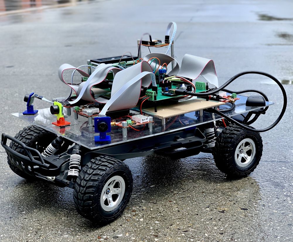
When over a century ago Karl Benz invented the first car, it came as a miracle to people. Now, Almost every household owns a car. The industry has come from a 20 Horse power producing 2.9 liter Ford Model T (1908) to a massive 1500 Horsepower 5 liter Koenigsegg Regera (2018). And as such, further developments into the driving industry are bound to come. One such major field is the realm of Driverless smart cars. This project focuses on developing a driverless smart car(model) that is capable of going from one place to the destination without any manual input, avoiding obstacles along the way.
Objectives & Introduction
Zeus revolves around several SJone boards that have LPC 1758 at the center......(continue here). Following are the objectives of this project.:
- Zeus should successfully navigate from a fixed starting point to a fixed destination based on GPS.
- Obstacles on the way should be avoided.
- Code should be 100% Unit-Tested
- Communication should be established between Zeus and a mobile phone through an APP.
Team Members & Responsibilities
- Neel Patel
- Team Lead
- Master Module
- Android App
- BLE Module
- Aman Chandan
- Material/ Components Manager
- GEO module
- Artik Shetty
- Wiki Report Manager
- Motor Module
- PCB Design
- Himanshu Gunjal
- Master Module
- Karan Daryani
- Car Layout Designer
- Motor Module
- PCB Design
- Namdev Prabhugaonkar
- GEO module
- PCB Design
- Oliver Zhu
- GIT repository Manager
- Sensor Module
- Wen Yuen Chao
- Sensor Module
- Unit Testing
Schedule
| Week# | Date | Task | Activities | Status | Completion Date |
|---|---|---|---|---|---|
| 1 | 02/12/19 |
|
|
|
|
| 2 | 02/19/19 |
|
|
|
|
| 3 | 02/26/19 |
|
|
|
|
| 4 | 03/05/19 |
|
|
|
|
| 5 | 03/12/19 |
|
|
|
|
| 6 | 03/19/19 |
|
|
|
|
| 7 | 03/26/19 |
|
|
|
|
| 8 | 04/02/19 |
|
|
|
|
| 9 | 04/09/19 |
|
|
|
|
| 10 | 04/16/19 |
|
|
|
|
| 11 | 04/23/19 |
|
|
|
|
| 12 | 04/30/19 |
|
|
|
|
| 13 | 05/07/19 |
|
|
|
|
| 14 | 05/14/19 |
|
|
|
|
| 15 | 05/22/19 |
|
|
|
|
Parts List & Cost
| Item# | Part Description | Vendor | Qty | Cost $ |
|---|---|---|---|---|
| 1 | RC Car | Sheldon's Hobby Store | 1 | 180.00 |
| 2 | SJOne board | Preet | 5 | 400.00 |
| 3 | GPS Module | Amazon | 1 | 62.99 |
| 4 | Lipo Battery (7200 mAh) | Amazon | 1 | 37.99 |
| 5 | DB9 Connector | Amazon | 1 | 6.50 |
| 6 | LIPO Battery Charger | Sheldon's Hobby Store | 1 | 39.99 |
| 7 | Ultrasonic sensor | Robotshop | 4 | 99.80 |
| 8 | PCB | Fry's Electronics | 1 | 12 |
| 9 | CAN Transceiver | Amazon | 5 | 49.95 |
| 10 | LCD Display | Obtained From Preet | 1 | Free |
| 11 | Xbee | Obtained From Preet | 1 | Free |
| 12 | Adapter for Lipo Charger | Amazon | 1 | 15.84 |
Design & Implementation
The design section can go over your hardware and software design. Organize this section using sub-sections that go over your design and implementation.
CAN BUS Design
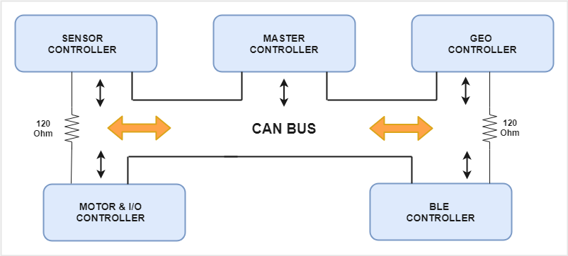
CAN Communication is used to communicate between all the boards and it requires the bus to be terminated using two 120 Ohm resistors. CAN is a broadcast bus. Based on the .dbc file, each module will transmit only selected messages. Receiving of the messages is enabled by filtering. The module can be configured to receive all messages or receive selected messages.
CAN 11-bit ID Format
We have used the 11-bit ID format for all the messages. The message ids have been defined to represent the transmitter, receiver and the message.
| SRC | DST | MSG |
|---|---|---|
| 3 bits (10-8) | 4 bits (7-4) | 4 bits (3-0) |
Controller ID Table
Each module has been assigned a number. This number is used to define the message ids.
| Controller ID | Controller Type |
|---|---|
| 0 | System Command |
| 1 | Master Controller |
| 2 | Sensor Controller |
| 3 | BLE Controller |
| 4 | Geo Controller |
| 5 | Motor Controller |
| 6 | I/O Controller |
CAN Communication Table
The table indicates the messages based on the transmitter.
| Sr. No | Message ID | Message function | Receivers |
|---|---|---|---|
| System Commands | |||
| 1 | 10 | System communication command | Master |
| Master Controller Commands | |||
| 2 | 100 | Master System Command for the all modules to start or stop processing | BLE, Geo, I/O, Motor, Sensor |
| 3 | 151 | Steer and Drive command for the Motor module | Motor, I/O |
| 4 | 162 | Display the active state of each module | BLE, I/O |
| Sensor Controller Commands | |||
| 5 | 211 | Obstacle Data | Master, I/O |
| 6 | 214 | Heartbeat | Master |
| 7 | 263 | Battery Health | I/O |
| BLE Controller Commands | |||
| 8 | 314 | Heartbeat | Master |
| 9 | 341 | Checkpoints | Geo |
| Geo Controller Commands | |||
| 10 | 411 | Calculated Direction for the car | Master |
| 11 | 413 | Destination Reached flag | Master, BLE, I/O |
| 12 | 414 | Heartbeat | Master |
| 13 | 431 | Start point | BLE, I/O |
| 14 | 461 | Compass data | I/O |
| Motor Controller Commands | |||
| 15 | 514 | Heartbeat | Master |
| 16 | 561 | Car speed | I/O |
| I/O Controller Commands | |||
| 17 | 614 | Heartbeat | Master |
DBC File
DBC file is designed based on the designed CAN messages and signals. Preet's python script is used to auto-generate CAN communication-related structures and functions. Each module will generate its specific generated_can.h by changing the module name in 'pre_build.sh' file. The following is the example of auto-generated code for the master module.
python ../_can_dbc/dbc_parse.py -i ../../snf.dbc -s MASTER > ../_can_dbc/generated_can.h
The DBC file for the project is as shown below:
VERSION ""
NS_ :
    BA_
    BA_DEF_
    BA_DEF_DEF_
    BA_DEF_DEF_REL_
    BA_DEF_REL_
    BA_DEF_SGTYPE_
    BA_REL_
    BA_SGTYPE_
    BO_TX_BU_
    BU_BO_REL_
    BU_EV_REL_
    BU_SG_REL_
    CAT_
    CAT_DEF_
    CM_
    ENVVAR_DATA_
    EV_DATA_
    FILTER
    NS_DESC_
    SGTYPE_
    SGTYPE_VAL_
    SG_MUL_VAL_
    SIGTYPE_VALTYPE_
    SIG_GROUP_
    SIG_TYPE_REF_
    SIG_VALTYPE_
    VAL_
    VAL_TABLE_
BS_:
BU_: DBG BLE GPS MOTOR SENSOR MASTER

BO_ 90 MASTER_HEARTBEAT: 1 MASTER
 SG_ MASTER_HEARTBEAT_cmd : 0|8@1+ (1,0) [0|0] "" MOTOR, SENSOR, GPS

BO_ 91 MOTOR_HEARTBEAT: 1 MOTOR
 SG_ MOTOR_HEARTBEAT_cmd : 0|8@1+ (1,0) [0|0] "" MASTER

BO_ 92 SENSOR_HEARTBEAT: 1 SENSOR
 SG_ SENSOR_HEARTBEAT_cmd : 0|8@1+ (1,0) [0|0] "" MASTER

BO_ 93 GPS_HEARTBEAT: 1 GPS
 SG_ GPS_HEARTBEAT_cmd : 0|8@1+ (1,0) [0|0] "" MASTER, BLE

BO_ 94 BLE_HEARTBEAT: 1 BLE
 SG_ BLE_HEARTBEAT_cmd : 0|8@1+ (1,0) [0|0] "" MASTER, GPS

BO_ 101 MOTOR_COMMAND: 2 MASTER
 SG_ STEER_cmd : 0|8@1- (1,0) [-2|2] "" MOTOR
 SG_ SPEED_cmd : 8|8@1- (0.1,0) [-1|3] "" MOTOR

BO_ 121 SENSOR_SONARS: 8 SENSOR
 SG_ SENSOR_SONARS_LEFT : 0|8@1+ (1,0) [0|0] "" MASTER
 SG_ SENSOR_SONARS_MIDDLE : 8|8@1+ (1,0) [0|0] "" MASTER
 SG_ SENSOR_SONARS_RIGHT : 16|8@1+ (1,0) [0|0] "" MASTER
 SG_ SENSOR_SONARS_BACK : 24|8@1+ (1,0) [0|0] "" MASTER

BO_ 141 DIRECTION_GPS: 2 GPS
 SG_ DIRECTION_VAL : 0|8@1- (1,0) [-2|2] "" MASTER
 SG_ DESTINATION_REACHED : 8|1@1+ (1,0) [0|0] "" MASTER

BO_ 161 SPEED_MOTOR: 2 MOTOR
 SG_ MOTOR_SPEED : 0|12@1+ (0.001,0) [0|0] "mph" MASTER

BO_ 181 APP_DATA: 8 BLE
 SG_ START_CAR : 0|2@1+ (1,0) [0|0] "" MASTER, DBG

BO_ 182 APP_DATA_LAT_LONG: 8 BLE
 SG_ DEST_LAT : 0|32@1+ (0.000001,0) [36.000000|38.000000] "" MASTER,GPS
 SG_ DEST_LONG : 32|32@1+ (0.000001,-123) [-123.000000|-120.000000] "" MASTER,GPS

BO_ 191 HEADING: 4 GPS
 SG_ HEADING_VAL : 0|32@1+ (0.000001,0) [0|0] "" MOTOR, DBG

BO_ 900 DEBUG_MASTER: 8 MASTER
 SG_ MASTER_LEFT_cmd : 0|8@1+ (1,0) [0|0] "" DBG
 SG_ MASTER_MIDDLE_cmd : 8|8@1+ (1,0) [0|0] "" DBG
 SG_ MASTER_RIGHT_cmd : 16|8@1+ (1,0) [0|0] "" DBG
 SG_ MASTER_BACK_cmd : 24|8@1+ (1,0) [0|0] "" DBG

BO_ 901 DEBUG_GPS: 8 GPS
 SG_ CURR_LAT : 0|32@1+ (0.000001,0) [36.000000|38.000000] "" DBG
 SG_ CURR_LONG : 32|32@1+ (0.000001,-123) [-123.000000|-120.000000] "" DBG

BO_ 902 DEBUG_COMPASS: 2 GPS
 SG_ HEADING : 0|16@1+ (1,0) [0|360] "degrees" DBG

BO_ 903 DEBUG_MOTOR: 3 MOTOR
 SG_ CURR_SPEED : 0|8@1+ (0.01,0) [0|0] "m/s" DBG
 SG_ REQD_SPEED : 8|8@1+ (0.01,0) [0|0] "m/s" DBG
 SG_ RPM_VALUE : 16|8@1+ (1,0) [0|0] "" DBG

BO_ 904 DEBUG_NAVIGATION: 8 GPS
 SG_ DIST_DIFF : 0|32@1+ (0.000001,0) [0|0] "m" DBG
 SG_ HEAD_DIFF : 32|32@1+ (0.000001,0) [0|0] "Degrees" DBG

BO_ 899 DEBUG_BEARING: 4 GPS
 SG_ BEARING : 0|32@1+ (0.000001,0) [0|0] "degrees" DBG,MOTOR

BO_ 898 DEBUG_CHECKPOINT: 1 GPS
 SG_ INDEX : 0|8@1+ (1,0) [0|0] "" DBG

BO_ 897 NXT_COORD: 8 GPS
 SG_ LAT : 0|32@1+ (0.000001,0) [36.000000|38.000000] "" DBG
 SG_ LONG : 32|32@1+ (0.000001,-123) [-123.000000|-120.000000] "" DBG

CM_ BU_ DRIVER "The driver controller driving the car";
CM_ BU_ MOTOR "The motor controller of the car";
CM_ BU_ SENSOR "The sensor controller of the car";
CM_ BU_ BLE "The bluetooth controller of car";
CM_ BU_ GPS "The GPS controller of the car";
CM_ BO_ 100 "Sync message used to synchronize the controllers";

BA_DEF_ "BusType" STRING ;
BA_DEF_ BO_ "GenMsgCycleTime" INT 0 0;
BA_DEF_ SG_ "FieldType" STRING ;

BA_DEF_DEF_ "BusType" "CAN";
BA_DEF_DEF_ "FieldType" "";
BA_DEF_DEF_ "GenMsgCycleTime" 0;

BA_ "GenMsgCycleTime" BO_ 500 100;
BA_ "GenMsgCycleTime" BO_ 100 1000;
BA_ "GenMsgCycleTime" BO_ 101 100;
BA_ "GenMsgCycleTime" BO_ 400 100;
BA_ "GenMsgCycleTime" BO_ 200 100;
BA_ "FieldType" SG_ 500 DBC_TEST1_enum "DBC_TEST1_enum";
BA_ "FieldType" SG_ 100 DRIVER_HEARTBEAT_cmd "DRIVER_HEARTBEAT_cmd";
VAL_ 500 DBC_TEST1_enum 2 "DBC_TEST1_enum_val_two" 1 "DBC_TEST1_enum_val_one" ;
VAL_ 100 DRIVER_HEARTBEAT_cmd 2 "DRIVER_HEARTBEAT_cmd_REBOOT" 1 "DRIVER_HEARTBEAT_cmd_SYNC" 0 "DRIVER_HEARTBEAT_cmd_NOOP" ;
Can Bus analyzer
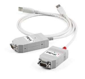
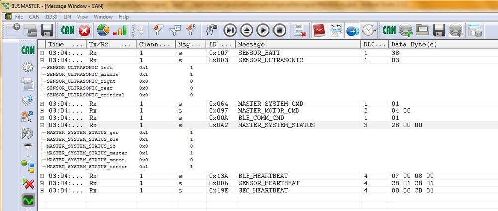
The PCAN-USB adapter enables simple connection to CAN networks. Bus Master software has been used to read and debug CAN messages. Bus Master requires DBC file to be converted to a .dbf file. The messages can be viewed in a very detailed format in the Bus Master. The bus master along with PCAN dongle is very useful in debugging the CAN communication. It is also possible to record the logs of communication.
Motor Module
Group Members
Design & Implementation
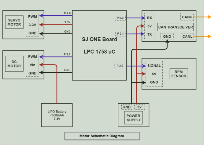
The motor module is one of the five controllers used in our self-driving car. The motor controller is responsible for driving the car forward or reverse and for steering the vehicle. The motor module has two motors viz.DC motor and Servo motor. DC motor makes the car move forward and reverse whereas the servo motor steers the car either left or right. Along with the two motors, we have the rpm speed sensor which is interfaced with our controller to calculate the speed of the car and move the car at the desired speed which is measured in meters per second (m/s). The front wheels have servo connection for turning. The chassis is placed on suspension unit for shock absorbing. An acrylic sheet is mounted over certain height on which the PCB and controller is placed. The motor controller sends signals for PWM and servo motor angles for driving the car.
Hardware Design
The Motor Module consists of 2 motors viz. DC motor and Servo motor controlled by an SJOne board by varying the PWM signals, which is nothing but the duty cycle. PWM stands for pulse-width modulation, a type of digital signal and can be used to control the motors. Along with two motors, an RPM sensor was interfaced with the motor module micro-controller to get the wheel feedback and move the car at a constant speed even if the car is going uphill or downhill. In case of communication loss from Master Controller, the Motor Controller displays a '0' on 7 Segment Display in CAN MIA condition.
Hardware Interface
Servo Motor
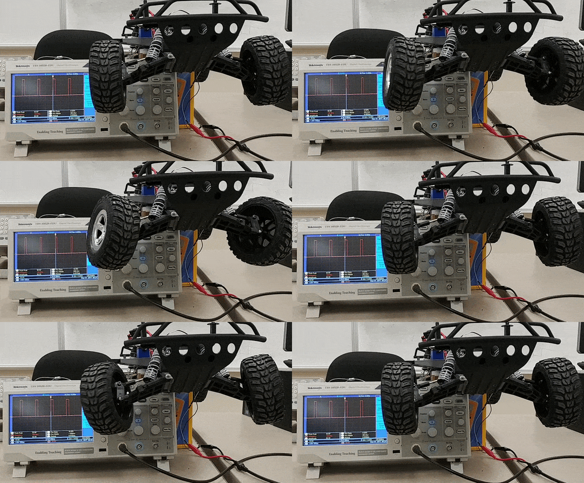
RC car came with a digital servo motor, requiring around 3-5V. The motor is directly controlled by giving a varying PWM signal from the SJOne board. Servo motor is used to convert an electrical signal into a linear motion. As per the PWM pulse received by the servo motor from SJOne board, it will rotate its shaft by a certain degree left or right. Below table gives the PWM values given to the motor for turning the car in the desired direction.
| No. | PWM | Direction |
|---|---|---|
| 1 | 5 | Full Left |
| 2 | 6 | Slight Left |
| 4 | 7 | Straight |
| 6 | 8 | Slight Right |
| 7 | 9 | Full Right |
DC Motor
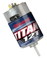
Like servo motor, the DC motor was also embedded in the RC car. The DC motor is used to convert an electrical signal into mechanical power. DC motor is controlled in the same manner as the servo motor i.e., by varying the PWM signal. The only difference here is that the PWM signal from the SJOne board is given to an Electronic Speed Controller or ESC. The ESC is used to generate three-phase electric power of low voltage in order to vary the speed of the DC motor. In case of no ESC, the DC motor will either not move or will start moving at full throttle. The RC car DC motor required 7.4V of power supply to work. The maximum speed that can be attained by this DC motor is 31mph.
Technical Challenges
Car Moving Too Fast While Downhill
Problem Summary: In spite of controlling speed using RPM sensor, the car was not in control while on a downhill.
Solution: After trying all possible solutions we could think of, we applied a brake momentarily at the start to reduce the sudden increase in PWM and then controlled the car based on the inclination. Also, made sure that if PWM value went below a certain range, then no brake was applied to the car.
Car Not Going in Reverse
Problem Summary: Although the PWM given to the car was ideal for making the Car go reverse. There was some issue with the car and it did not go reverse at all.
Solution: When checked with the transmitter/remote, I was seen that for the car to go reverse we had to first give a reverse signal then a stop signal and again a reverse signal. We implemented this easily with a simple block of code and manage to get the ESC working.
Servo Movements were slow
Problem Summary: Proper PWM Signals was given to the servo for going left or right but the movements were too slow.
Solution: Previously the Servo was running at 3.3v. After checking its manual realised that the servo works better and swift with 5v. Thus powered the servo motor with 5v and it started working prompty.
PWM being initialised at 1.9kHz instead of 50Hz
Problem Summary: Initialised the PWM Peripherals to 50Hz. But when checked on the same on a Digital Oscilloscope the value was 1.9kHZ.
Solution: When reviewing the code we realised that we have initialised the PWM peripheral but that code was not actually executed. We solved this by using a pointer instance of the PWM and initialising the PWM Signal in the motor init function.
Geographical Controller
Team Members:
The main purpose of the geographical controller is to guide the car towards its destination. This is done by processing data from the GPS and Compass module in order to get the Heading, Bearing, and Distance. The compass will allow the user to calculate the Heading, which tells us which direction the car is pointing relative to magnetic north or simply, "Which way the car is pointing"? The GPS will allow the user to get the current coordinates of the car, which will be useful when calculating the Bearing and Distance. The Bearing tells us the direction from the current location to a checkpoint coordinate, and is given as the angle between the location and the current location of the car. The Distance tells us how many meters away the current checkpoint is. Essentially, How far away are we from our destination?
The geographical controller is also responsible for:
1. Parse the data from GPS and Compass module.
2. Navigate a path towards the destination using the nearest checkpoint
2. Navigate to nearest checkpoints and to set course towards the nest checkpoint along the path towards the destination .
3. Setting up the heading of the car towards the direction of the next checkpoint .
Hardware Design
Pin Configuration:
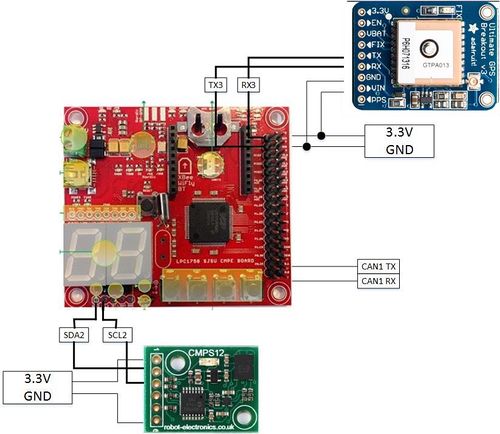
| Sl. No | Pin on SJOne Board | Pin on CMPS12 | Purpose |
|---|---|---|---|
| 1 | SDA | SDA | Serial Data pin from SJONE to CMPS12 |
| 2 | SCL | SCL | Clock signal from SJONE to CMPS12 |
| 3 | 5V | VCC | 5V voltage supply |
| 4 | GND | GND | Ground |
| Sl. No | Pin on SJOne Board | Pin on Adafruit Ultimate GPS Breakout | Purpose |
|---|---|---|---|
| 1 | TXD3 | RXD | Transmit using UART3(TXD3) to Adafruit Ultimate GPS Breakout |
| 2 | RXD3 | TXD | Receive using UART3(RXD3) from Adafruit Ultimate GPS Breakout |
| 3 | 5V | VCC | 5V voltage supply |
| 4 | GND | GND | Ground |
Hardware Interface
CAN Bus
The CAN bus interface allows the geographical controller to send and receive data from other microcontrollers on the bus. For example, the geographical controller will send requests to the master controller to tell it to turn right, left, or keep straight in order to reach the set checkpoints. The geographical controller will plan a path towards the destination using the closest checkpoint towards the destination path and then send the steer commands to be taken in order to to steer towards the destination.
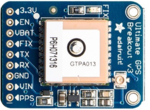
MTK3339 Ultimate GPS
The MTK3339 Ultimate GPS module from Adafruit was chosen because it is a plug and play device and gives consistent GPS string The main purpose of the GPS module is to provide an accurate location of the car while the car navigates towards its destination. This is done by parsing NMEA sentences, which are transmitted by up to 66 satellites to pinpoint the current location of the module. There are various different types of NMEA sentences, such as $GPRMC and $GPGGA. The NMEA sentence that was used was $GPGGA, which provides only the recommended minimum. The module is interfaced via UART with a baud-rate set to 57600bps. The module also comes with a fix LED, which indicates if a GPS fix by blinking every 15 seconds, if not, it blinks every 1Hz. The module is powered by 3.3V from the SJOne board.
The $GPGGA sentence is separated by commas, which the user has to parse in order to get useful data out of the module. The most important data that the user want is the GPS coordinate, Latitude and Longitude.The parsing of data was done using the strstr() function which returns the pointer of the comma from the NMEA string to be parsed.
Below is an example of a parsed $GPGGA sentence:
      Example:  $GPGGA,123519,4807.038,N,01131.000,E,1,08,0.9,545.4,M,46.9,M,,*47

                     1     2    3    4    5     6    7    8      9     10  11 12
| Number | Raw form | Description |
|---|---|---|
| 1 | 123519 | Time of fix 12:35:19 UTC |
| 2 | A | Navigation receiver warning A = OK, V = warning |
| 3 | 4807.038 | Latitude 48 deg. 07.038 min |
| 4 | N | North |
| 5 | 01131.000 | Longitude 011 deg. 31.00 min |
| 6 | E | East |
| 7 | 1 | Fix Quality, 1 means GPS is fixed |
| 8 | 08 | Number of satellites being tracked |
| 9 | 0.9 | Horizontal dilution of position |
| 10 | 545.5,M | Altitude, Meters, above mean sea level |
| 11 | 46.9,M, | Height of geoid (mean sea level) above WGS84 |
| 12 | *68 | the checksum data, always begins with * |
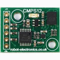
CMPS12 - Tilt Compensated Magnetic Compass Module
The CMPS12 - Tilt Compensated Magnetic Compass module was chosen because it provides better performance than its predecessor CMPS12, the module also has a 3-axis magnetometer, a 3-axis gyro and a 3-axis accelerometer. The CMPS12 is a self calibrating module and is automatically calibrated by movement, there is no instigation required by the user.Register 30 can be checked to see the level to which the CMPS12 has been calibrated. The default mode of the compass was chosen to get the heading value. The compass needs to be calibrated initially by moving it around in 3 axis. The calibration profiles stays onto it until the power supply to compass module is taken off.
The compass module is placed away from all other components of the car to minimize any magnetic interference from the motor, servo, sensors, and microcontrollers. Placing it in an environment where there is magnetic interference will cause incorrect reading of the heading and the car will navigate towards the wrong direction. The compass and GPS module is placed on a higher mount on the car to avoid any interference to it.The compass module is interfaced via I2C. It is powered on by 5V, but 3.3V works also.
.
Software Implementation
GEO module sends the direction and heading values to the master controller.
| Sl. No | Message ID | Message name | Purpose |
|---|---|---|---|
| 1 | 141 | DIRECTION_GPS | Send direction value to the master |
| 2 | 191 | HEADING | Send Heading value in degrees to the master |
Receiving and parsing GPS data
The first task was to interface the GPS module to the SJOne board (using UART3), and receive raw data over it. The module was configured to receive only GPGGA NMEA sentence at 9600 bps baud rate. The received NMEA data is a string, that has to be parsed to obtain current latitude and longitude values. This location data is continuously sent to the Master controller on the CAN bus at 10 Hz.
Heading Calculation
Heading of the car is the direction that the car is moving, with respect to true north. A compass gives heading with respect to magnetic north. T\
The CMPS12 is calibrated by tilting it around in 3 axis. The CMPS12 is connected to the SJONE board using the I2C connection.
Bearing calculation
Bearing is the direction that the car desires to travel along, i.e., the direction of the destination. It is calculated using the current location coordinates and the destination coordinates (or next checkpoint coordinates). The formula to calculate bearing is
   X = cos(lat2) * sin(dLong)
   Y = cos(lat1) * sin(lat2) - sin(lat1) * cos(lat2) * cos(dLong)
   Bearing = atan2(X,Y)

   where,
   (lat1, long1) are the current location coordinates
   (lat2, long2) are the checkpoint coordinates
   dLong is (long2 - long1)
Distance calculation
The distance between the current location and the next checkpoint is calculated using the Haversine formula .
Haversine formula: a = sin²(Δφ/2) + cos φ1 ⋅ cos φ2 ⋅ sin²(Δλ/2) c = 2 ⋅ atan2( √a, √(1−a) ) d = R ⋅ c where φ is latitude, λ is longitude, R is earth’s radius (mean radius = 6,371km); note that angles need to be in radians to pass to trig functions!
A flag is set when the distance to the final checkpoint becomes zero, and sent to the Master controller, to indicate that the destination has been reached.
Testing & Technical Challenges
Issues
<Please Write in bullet points if you can> Following were the problems faced and their resolutions:
Problem 1: Calibration of CMPS 12 module.
Solution 1: We initially started by writing our own calibration profile into the registers of the CMPS12 module. After noticing that the calibration values were inconsistent we erased the profile that we wrote and used the default calibration profile.
Testing
<Provide Testing method that were implemented>
Sensors Controller
Group Member
- Oliver Zhu
- Wen Yuen Chao
Hardware Design
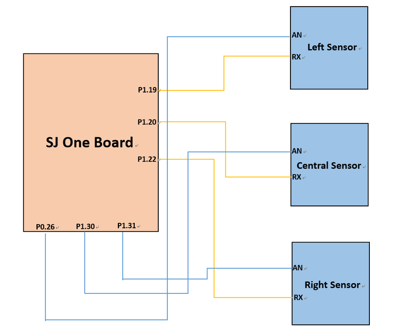
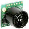
In this project, the sensor we use is LV-MAXSonar-EZ4, which is ultrasonic sensor. There are three sensors put in the front of our RC car and detect the left, middle and right side independently.
The feature of this sensor as follows:
1. 2.5V to 5.5V supply with 2mA typical current draw
2. Readings can occur up to every 50mS (20-Hz rate)
3. Serial, 0 to Vcc, 9600 Baud, 81N
4. Analog, (Vcc/512) / inch
5. Pulse width, (147uS/inch)
The benefit of the sensor as below:
1. Very low cost ultrasonic rangefinder
2. Very low power ranger, excellent for multiple sensor or battery-based systems
3. Quality beam characteristics
| Sl. No | Pin on SJOne Board | Pin on MaxSonar-EZ4 | Purpose |
|---|---|---|---|
| 3 | PWM | AN | PWM pin from SJONE to MaxSonar-EZ4 |
| 4 | RX | RX | Recive data from SJONE to CMPS12 |
| 6 | 5V | VCC | 5V voltage supply |
| 7 | GND | GND | Ground |
Hardware Interface
CAN Bus
The CAN bus interface allows the sensor controller to send and receive data on the bus. For example, the sensor controller will send the data to the CAN bus and the master controller will take it and let the car to do the coordinate movement.
Software Design
1. Initialization sequence
In the Sensor init sequence is as follows:
- CAN Init
- Motor CAN is initialized on can1 with BAUD rate 100bps and TX/RX queue sizes of 100. Then the filter is setup for 100-150 MSG IDs.
- Sensor Init
2. Read Sensor
The relative functions is as follows:
- read_sensor
- After reading the data from sensor, we have to transfer the voltage to inch.
- read_sensor_left
- Read the data from left sensor.
- read_sensor_right
- Read the data from right sensor.
- read_sensor_center
- Read the data from center sensor.
3. Filter the value of sensor
The relative functions is as follows:
- filter_sensor
- Sometime we will get the outlier by noise, so we need to eliminate this abnormal value.
Testing & Technical Challenges
Problem 1: There is a unusual pulse when sensor sent the date to CAN bus.
Solution 1: When we meet the unusual value, we will adopt the previous value rather than the current value.
Testing
In the code of sensor part, we use API of CMock to test our code. There is a example we used as follows:
void test_sensor2chan(void)
 {
   TEST_ASSERT_EQUAL(3, sensor2chan(sensor_left)); //0+3
   TEST_ASSERT_EQUAL(4, sensor2chan(sensor_center)); //1+3
   TEST_ASSERT_EQUAL(5, sensor2chan(sensor_right)); //2+3
   TEST_ASSERT_EQUAL(6, sensor2chan(sensor_back)); //3+3
 }
void test_read_sensor(void)
 {

   uint16_t adc = 2;
   enum sensor_dir sensor = sensor_left;
   trigger_sensor_ExpectAndReturn(sensor, true, true);
   adc0_get_reading_ExpectAndReturn(sensor2chan(sensor), adc);
   sensor_delay_ms_Expect(1);
   trigger_sensor_ExpectAndReturn(sensor, false, false);
   sensor = sensor_center;
   trigger_sensor_ExpectAndReturn(sensor, true, true);
   adc0_get_reading_ExpectAndReturn(sensor2chan(sensor), adc);
   sensor_delay_ms_Expect(1);
   trigger_sensor_ExpectAndReturn(sensor, false, false);
   sensor = sensor_right;
   trigger_sensor_ExpectAndReturn(sensor, true, true);
   adc0_get_reading_ExpectAndReturn(sensor2chan(sensor), adc);
   sensor_delay_ms_Expect(1);
   trigger_sensor_ExpectAndReturn(sensor, false, false);
   sensor = sensor_back;
   trigger_sensor_ExpectAndReturn(sensor, true, true);
   adc0_get_reading_ExpectAndReturn(sensor2chan(sensor), adc);
   sensor_delay_ms_Expect(1);
   trigger_sensor_ExpectAndReturn(sensor, false, false);
   sensor2type(sensor_left);
   sensor2type(sensor_center);
   sensor2type(sensor_right);
   sensor2type(sensor_back);
   TEST_ASSERT_EQUAL(3.15, read_sensor(sensor));

 }
Android Application and Bridge
Group Members
Design
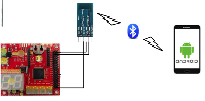
The bridge controller is responsible for establishing communication between the CAR and an Android Phone. This communication is achieved using Bluetooth technology and HC-05 bluetooth transceiver. The android app "ZeusApp" sends Co-ordinates as well as Start/Stop command to the car. Once the bridge ECU receives this data over UART, it transmits it to corresponding controllers using CAN bus. The HC-05 module communicates with SJONE over UART at 9600bps baud rate. The overall architecture of the system is given below:
Pin Configuration:
| Sl. No | Pin on SJOne Board | Pin on HC-05 | Purpose |
|---|---|---|---|
| 1 | TXD3 | RXD | Transmit using UART3(TXD3) to HC-05 |
| 2 | RXD3 | TXD | Receive using UART3(RXD3) from HC-05 |
| 3 | 3V3 | VCC | 3.3V voltage supply |
| 4 | GND | GND | Ground |
Hardware interface between the BLE ECU and The can bus is achieved using the CAN tranciever. P0.1 on the SJone board is connected to CAN Tx and P0.0 is connected to CAN Rx. The CAN bus section talks in more detail about how CAN is actually implemented.
Bluetooth Hardware Design
We decided to go with HC-05 as our bluetooth module HC-05 because of the vast amount of information on it on the internet. HC-05 is an easy to use Bluetooth SPP(Serial Port Protocol) module, designed for transparent wireless serial connection setup. Hc-05 also provides switching mode between master and slave mode. Given below are features of HC-05:
- -80dBm sensitivity
- Up to +4dBm transmit power
- Low Power operation
- UART interface with programmable baud rate.
- Integrated Antenna and edge connector.
- Supported Baud Rate: 9600,19200,38400,57600,115200,230400,460800.
- Auto-connect to the last device on power as default.
- Auto-pairing PINCODE:”0000” as default
- Auto-reconnect in 30 min when disconnected as a result of beyond the range of connection.
Bluetooth Software Design
The BLE ECU is responsible for receiving data over UART and then Packaging it in correct message format and sending it over the can bus. To achieve this a few messages were made in the DBC file. The Message IDs and info is given in the table below:
| Sl. No | Message ID | Message name | Purpose |
|---|---|---|---|
| 1 | 181 | APP_DATA | Sends 2 bit start OR stop command |
| 2 | 182 | APP_DATA_LAT_LONG | Send Destination Latitude and Longitude to the ECU. |
Our BLE ECU is pretty simple and has one function as its core operation. This Function is given below.
void parse_data()
{
   char coord[100]={0};
   getstring(coord,100,0);
   if(coord[0]==1)
   {
       printf("\nStart");
       BLE_data.START_CAR=1;
       c_LED_display_set_number(1);
       memset(coord,0,sizeof(coord));
   }
   else if(coord[0]==2)
   {
       printf("\nStop");
       BLE_data.START_CAR=2;
       c_LED_display_set_number(0);
       memset(coord,0,sizeof(coord));
   }
   else if(strlen(coord))
   {
       while(coord[i] != ',')
       {
               Latitude[i]=coord[i];
               i++;
       }
      Latitude[i]='\0';
       i++;
       while(coord[i] != '@' )
       {
           Longitude[j]=coord[i];
           i++;
           j++;
       }
       Longitude[j]='\0';
       i=0;
       j=0;
       float LAT1=atof(Latitude);
       float LON1=atof(Longitude);
       printf("\nLatitude: %.15f",LAT1);
       printf("\nLongitude: %.15f",LON1);

       gps_destination.DEST_LAT=LAT1;
       gps_destination.DEST_LONG=LON1;
   }
   dbc_encode_and_send_APP_DATA(&BLE_data);
   dbc_encode_and_send_APP_DATA_LAT_LONG(&gps_destination);
}
As seen in the code above, there are two DBC structures that are made, BLE_data to send start/stop command and gps_destination to send the destination co-ordinates. The android app sends a string over bluetooth to HC-05 which passes it on to SJone over UART. By parsing this string we can figure out which command was received from the App. If the 1st character of string is '1' the its a START command, if its '2' the it is STOP command and otherwise it parses the string to find Coordinates. Through the app i am sending coordinates in the format of LATITUDE,LONGITUDE so, in parse_data() function, two global character arrays were accessed. Until the iterator reaches the comma it puts everything in the Latitude array and after the till the end of string it puts everything in the Longitude array. Library function atof() was used to convert the character array to float to be able to send it over CAN.
The function parse_data() is periodically called at 1hz (so every one second). This means that the UART data is parsed and a can message is sent every second.
Android Application Design
Implementation
The main purpose of the android application is to provide the user with a way to interact with the Car using a smartphone. This app was built using Android Studio developed by Google and Jetbrains. You have the option of writing the code in either Java or Kotlin. For ZeusApp we decided to go with Java. One of the most important features that needed to be integrated into the app was Google Maps to show current position and the destination coordinates. A Google Maps API key is required to integrate Maps withing the application. This key can be acquired through the Google Developers Console. This key is mainly used to track activity of the app. Google uses the tracking to figure out charges (if any). Since our app is not a public app it doesnt cost anything for us. There are two main activities that form the app.
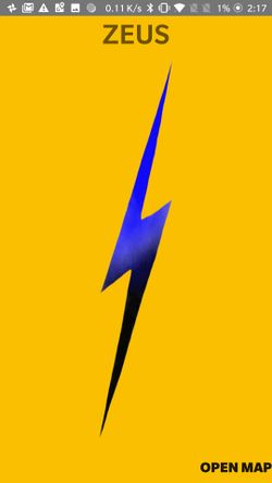
1. StartScreen.java is the first page that the user is greeted with its a basic home page that allows the user to go to the Map where he/she can interact with the car.
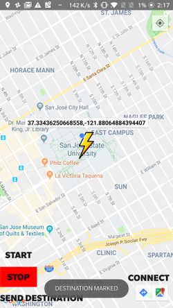
2. MapDemoActivity.java is the main activity where all the important work happens. This is the page which displays Google map fragment and all the controls associated with the car. The map fragment loads and updates the users location which he/she can see by clicking the recenter button. A pin can be dropped on the map by just touching the desired location on it. This activity also lets user connect to HC-05 bluetooth transceiver by simply clicking the Connect button. Once the app is connected to the car, user can then start the car using START button and similarly stop it using the STOP button. After marking the destination there is a button that lets the user send coordinates in the form of LATITUDE, LONGITUDE to the car.
Bluetooth - Android Side
The MapDemoActivity.java , besides UI for map. has one more integral purpose. It establishes a socket communication between the smartphone and HC-05 transceiver. For this a few things need to be done.
1. We need to specify certain permission in the AndroidManifest.xml. These permissions are given below
<uses-permission android:name="android.permission.BLUETOOTH" />
<uses-permission android:name="android.permission.BLUETOOTH_ADMIN" />
2. Import the following libraries
import android.bluetooth.BluetoothAdapter;
import android.bluetooth.BluetoothDevice;
import android.bluetooth.BluetoothSocket;
import android.content.BroadcastReceiver;
import java.io.InputStream;
import java.io.OutputStream;
This lets us define variables that are needed for establishing communication over bluetooth. Input and Output stream classes lets us make buffers to write data to and read data from.
3. For basic communication we need need three things a Bluetooth Device, Bluetooth Adapter and a Bluetooth Socket. These are declared as follows:
BluetoothSocket mBTsocket = null;
BluetoothDevice BoardSJONE = null;
BluetoothAdapter ZeusAdapter;
Bluetooth adapter lets you represent local device(smartphone) bluetooth adapter and lets you perform bluetooth tasks such as device query, instantiate a BluetoothDevice using MAC ID or UUID and create a socket. The Bluetooth adapter itself can be initialized as follows:
ZeusAdapter = BluetoothAdapter.getDefaultAdapter();
For this app we have initialized the adapter int the onStart function. This funtion is called when the activity becomes visible to the User, so, before anything can be done BluetoothAdapter is initialized.
4. Once the Adapter has been initialized and the device has been paired we now need to establish RF communication between the phone and HC-05. For that we use BluetoothSocket as below.
mBTsocket = BoardSJONE.createInsecureRfcommSocketToServiceRecord(BTMODULEUUID);
mBTsocket.connect();
pairedDevice = BoardSJONE;
Here, BTMODULEUUID is the Universallu Unique Identifier which is a 128 bit ID of the smartphone. Now the Socket connection has been established.
5. For sending data, Output Stream can be used.
tOUTPUT = mBTsocket.getOutputStream();
tOUTPUT.write(string.getBytes());
tOUTPUT.flush();
The parameters inside write() function is the data you want to send over bluetooth. A coordinate string in our case.
The diagrams below show our App as its seen on an Android phone:
For starters, i developed the app just to establish Socket communication with HC-05 and Send 1 or 0. Sort of like a "hello World" code. It was a bit of a learning curve. After successful communication establishment, the Start and Stop buttons were added. These would just let the user choose wether to send "1" (start) or "2" (stop). I decided to not go with 0 as the stop command as in the BLE file, character receive array is initiated to ZERO every time parse_data() function is called. This is because the array is defined locally and not globally for the function. So now only when a "2" is received over UART the DBC struct variable is set to STOP.
The second major task was building the map screen. This was a bit difficult as it requires Google API key to instantiate a Map fragment. The features i had to add include Toast messages on every new activity, Destination Coordinate marker. User Location marker and Bluetooth Buttons. Once the map was successfully integrated adding the Custom Destination marker (lightning bolt) was pretty straight forward to add. A slight modification int the function that loads the map needs to be made. Given below is the code snippet for adding a marker.
map.setOnMapClickListener(new GoogleMap.OnMapClickListener() { //marker added :neel
           @Override
           public void onMapClick(LatLng point) {
               Toast.makeText(getApplicationContext(),"DESTINATION MARKED",Toast.LENGTH_LONG).show();
               marker.position(point);
               marker.title(point.latitude + "," + point.longitude);  // point is an object of LatLng class , LAT and LON both are Doubles.
               //marker.title("Destination");
               marker.draggable(true);
               marker.icon(BitmapDescriptorFactory.fromResource(R.drawable.flash));
               //Destination_location.setLatitude(point.latitude);
               //Destination_location.setLongitude(point.longitude);
               Dest_point=point;
               map.clear();
               map.addMarker(marker);
           }
       });
Dest_point in the above snippet is the private class variable that is used to send the destination over Bluetooth. It is a LatLng class object.
Testing and Technical Challenges
Issues
- With Zero experience of Java or Android Application development, it was very difficult fo me in the beginning to learn Java syntax and get accumulated with the Android SDK. This was made possible after spending a lot of time on Android Developer website and Android tutorial on Youtube. The website provides information on available APIs and their examples.
- Running background activity for bluetooth. So that we could have Start/Stop on home screen and Send Destination feature on the mapscreen, was very difficult since i could not understand multithread bluetooth architecture. In the end the best solution to this was have one main activity(in our case the MapActivity) and have all the bluetooth buttons on that page.
- On the BLE side, in the beginning we observed that unless Explicitly sending Start (1) from the app the BLE would by default put a Stop(0) command on the CAN bus. This was because the character array was getting initialized to 0 every function call. This was solved by simply sending a "2" from the app, and then sending a Stop command only when the first character in the string is 2.
- Another major issue was that i was unable to send correct LAT LONG on the can bus in float format. We needed to have atleast 6 decimal point precision and this could only be achieved using a factor of 0.0000001 in the DBC. But even after doing that we would get positive coordinate value only upto 4 decimal points and would get total garbage for negative coordinate value (Latitude in our case is in the range of -121). Preet gave us a great idea to just send the entire number as a uint32_t variable and then divide it by a million on the receiver side(GPS in our case). This solved the problem and we were able to send and receive correct and precise Coordinates on the can bus.
Testing
- We began testing the BLE Uart code first for this, after writing a very basic code that would just take a character from uart and display it on screen, we installed an app directly from the Play Store for android. There are several Apps available on the app store for HC-05. Once the data sent from app was successfully received and displayed, we could move on to the next stage.
- On the android side the Map Fragment testing was done using an Android Studio Virtual Device (API 27). This helped us in deciding the layout and functions of each activity without having to deploy it on the smartphone.
- IMPORTANT: It should be noted that to test the bluetooth features of the app, an actual compatible android phone is needed since the emulator does not take permissions from the laptop's bluetooth adapter. We realized this after the App kept crashing on the emulator every-time a button was pressed.
Master Controller
Hardware Design
Software Design
Testing & Technical Challenges
Describe the challenges of your project. What advise would you give yourself or someone else if your project can be started from scratch again? Make a smooth transition to testing section and described what it took to test your project.
Include sub-sections that list out a problem and solution, such as:
<Bug/issue name>
Discuss the issue and resolution.
Conclusion
Conclude your project here. You can recap your testing and problems. You should address the "so what" part here to indicate what you ultimately learnt from this project. How has this project increased your knowledge?
Project Video
Upload a video of your project and post the link here.
Project Source Code
References
Acknowledgement
Any acknowledgement that you may wish to provide can be included here.
References Used
List any references used in project.
[1] Android Developers
Appendix
You can list the references you used.
Datasheets
[1] [Ultrasonic Sensor]
[2] Bluetooth Module
[3] [ LCD]
[4] CAN Transceiver
[5] GPS Module
[6] Compass Module
