F18: Goals of Glory
Contents
Project Title
Goals of Glory
Abstract
Gesture-based gaming is getting tremendous adoption due to immersive gameplay and increased player engagement. Goals of Glory is a classic penalty shootout game where 2 players can play wirelessly, and the corresponding game visuals are displayed on the LED Matrix in real time. The logic for player movement is based on the output from a Gyroscope and an Accelerometer embedded on MPU 6050 whereas accelerometer on the SJone helps drive goalkeeper movements. Thus the motion of player leg movements to kick and hand movements of the goalkeeper to stop the ball is mapped and the corresponding game animations are displayed on 64x64 LED Matrix. The LED matrix is interfaced to the SJone board in such a way that the main SJone board controlling the LED Matrix receives commands wirelessly from hand and leg movements of each player via the Nordic wireless mesh network. Three display screens are developed for the game UI- Start screen, Game screen, and Result screen. Thus, by playing Goals of Glory, players can experience gesture-based gaming capabilities.
Objectives & Introduction
Introduction
Our project is divided into 4 modules
1) LED Module: The 64x64 LED matrix is driven by a Master SJone board which is responsible to map game visuals.
2) Wireless Module: Responsible for communication medium between the goalkeeper, player, and main SJone board
3) Player Module: This module is responsible for getting the player movement that will be mapped to drive game visuals
4) Goalkeeper Module: This module is responsible for getting the goalkeeper movement that will be mapped to drive game visuals
Game Stats:
- 2-Player Penalty shootout Game
- 3-sec timer for each player to shoot
- Press switch on the main SJOne board to start
- Move the Goalkeeper SJone board left-right to have a corresponding movement of LED Matrix
- Control the ball movement via player SJone board to give direction i.e. left, right or straight
- Highest player to score wins and is displayed on the result screen
Objectives
Our project involved a focused and rigorous approach to testing each module functionality and make necessary changes thereafter.
- Design power management PCB
- Developing game visuals for the penalty shootout game.
- Developing logic for display tasks such as curving the ball, selecting the player and ball color.
- Implement RGB LED matrix driver
- Perform RGB LED matrix pin layout with the SJone board and have a deep understanding of how a single or group of LED's are driven.
- Perform accelerometer driver
- Perform nordic wireless driver
- Have a proper synchronization between the player SJone board and goalkeeper SJone board
- Examine overall system and make necessary tweaks
- Prepare the entire system for demo purpose which includes gloves and mounting pads to mount hardware equipment
Team Members & Responsibilities
- Player Movements
- Aniket Phatak
- Bhargav Shashidhara Pandit
- Goalkeeper Movements
- Tahir Rawn
- Harmeen Joshi
- Display (RGB LED Matrix)
- Harmeen Joshi
- Tahir Rawn
- Satya Sai Deepak. Naidu
- Wireless (Nordic)
- Aniket Phatak
- Bhargav Shashidhara Pandit
- PCB Design
- Satya Sai Deepak. Naidu
Schedule
| Week# | Date | Task | Status |
|---|---|---|---|
| 1 | 09/25 |
|
|
| 2 | 10/02 |
|
|
| 3 | 10/9 |
|
|
| 4 | 10/23 |
|
|
| 5 | 10/30 |
|
|
| 6 | 11/06 |
|
|
| 7 | 11/13 |
|
|
| 8 | 11/20 |
|
|
| 9 | 11/27 |
|
|
| 10 | 12/4 |
|
|
| 11 | 12/19 |
|
|
Parts List & Cost
| Item# | Part Desciption | Vendor | Qty | Cost |
|---|---|---|---|---|
| 1 | SJOne Boards | Preet | 3 | $240.00 |
| 2 | 64x64 RGB LED Matrix | Sparkfun | 1 | $75.00 |
| 3 | Power Adaptor Cable | Amazon | 1 | $9 |
| 4 | PCB | PCBWay [1] | 10 | $30 |
| 5 | MPU 6050 | Amazon | 2 | $11 |
| 6 | WiFi Antenna | Amazon | 3 | 24 |
| 7 | Mounting gloves | Amazon | 1 | $20 |
| 8 | Power Bank | Amazon | 2 | $24 |
| 9 | Miscellaneous (Jumper wires, Connectors, SMD's) | CMPE Lab 294 | $5 | |
| 9 | Total |
Design & Implementation
The design section can go over your hardware and software design. Organize this section using sub-sections that go over your design and implementation.
Hardware Design
The Hardware design for our project Goals of Glory involves usage of 3 SJone boards, a 64x64 LED matrix, MPU6050 gyroscope & accelerometer sensor, MMA8452Q accelerometer and nordic wireless (nRF24L01+) as described below.
Nordic Wireless
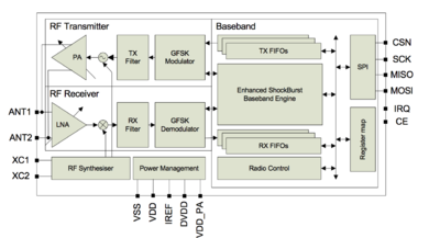
SJOne board is interfaced with Nordic wireless (nRF24L01+) using SPI.
The nRF24L01+ is a single chip 2.4GHz transceiver with an embedded baseband protocol engine, suitable for ultra low power wireless applications. The nRF24L01+ is designed for operation in the frequency band of 2.400 - 2.483GHz.
Printed Circuit Board (PCB) Design
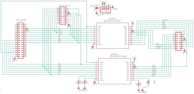
Introduction: The game uses a 64x64 LED Matrix which needs a 5v input supply. Since the board supplies 3.3v we level shift the voltage to 5v to avoid any unwanted flickering. So, we have decided to design a level shifter circuit. The design starts with the schematics and then designing the footprint. The design ends with creating the Gerber files and sending them to the manufacturing unit.
Schematics: The design was made in Eagle PCB design software. In preparing your schematics we encountered few challenges with the selection of equipment dimensions and dimension terminology(units). The designer should be aware of the dimensions of equipment that are to be used. After getting the idea of equipment,add the library of that equipment to eagle through manage library option. Now, the designer can get that item schematic and add it to the design schematics. Complete the schematics based on the circuit that the designer wants to implement. Figure.1 shows the schematics for level shifter circuit.
Few tips for schematics:
• Make sure the dimensions of auxiliary equipment size match the equipment. For example, the supply port size is 4mm pitch 4 pins if I use 2mm pitch 4pins my circuit is practically cannot be implemented.
• Have a clear idea of the equipment and their availability in the market before getting started. Sometimes your design may be correct, but you will not be getting appropriate equipment for installing on circuit board. • Use Vcc and Gnd pins for reducing circuiting complexity.
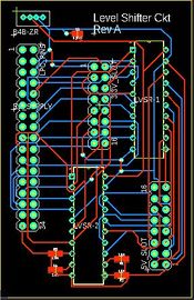
Foot Print and Gerber Files: After the schematics are done, you can see a BRD/SCH button i.e. schematic to board button. Using that button, the footprint page will be opened. Here you will be able to use some skills in designing a compact circuit. Selecting the trace width (in mils) accordingly based on your current ratings. We used a 2 layered 16 mils trace width for safer side to accommodate 4A flow of current. Place all your equipment in the square (board area) and can have positioned them upon the designers will. Click on auto net list button to run the simulations for possible tracing options
The designer can select one or draw the traces manually( manual is mostly preferred for better results).The foot print of out circuit is shown in Figure.2. Now, continue with DRC(design real check ) to check the possible errors while manufacturing. Make sure that there are no errors. After all the errors are cleared create the Gerber files for manufacturing company to provide those files to the manufacturing machines.
Software Design
Show your software design. For example, if you are designing an MP3 Player, show the tasks that you are using, and what they are doing at a high level. Do not show the details of the code. For example, do not show exact code, but you may show psuedocode and fragments of code. Keep in mind that you are showing DESIGN of your software, not the inner workings of it.
Implementation
This section includes implementation, but again, not the details, just the high level. For example, you can list the steps it takes to communicate over a sensor, or the steps needed to write a page of memory onto SPI Flash. You can include sub-sections for each of your component implementation.
Testing & Technical Challenges
Issues, Challenges and solutions to get past them
1. Designing the RGB LED Matrix Display driver
a) Writing the driver function on our own was a challenge. We were able to easily glow a single row in the matrix. However, the challenge lied in glowing a single pixel value at a specified location. And lack of datasheet made it even more difficult. Once we got the control over glowing a single LED (check updateDisplay function as shown above), we were able to implement various functions to draw lines, squares, triangles, car, digits, text.
b) Matrix flickering Issue
c) Ball animation to swing the ball
- We wrote an algorithm to find the path of the ball from the start point to endpoint (goalpost) to appear as if it were swinging
d) Limit the horizontal and vertical movement of the goalkeeper
- To avoid the goalkeeper moving out of the desired range, we used static variables to hold the valid position of the goalkeeper when the arguments are outside the valid range.
e) To resize the goalpost
- To change the goalpost dimensions it would be a difficult task to change it pixel by pixel.
The application has a task to call updateDisplay() function to update the buffer every 1ms. This task had a lower priority as compared to the player transaction task in the Master module. As a result of this, the LED Display Matrix was being updated at a slower rate, and thus, leading to matrix flickering. The issue was resolved by changing the priority of the updateDisplay matrix task higher than the Player task.
2. Designing the Gyroscope and Accelerometer driver for goalkeeper and player movements
3. Designing the Wireless driver
4. Dimensions of power pins for the PCB design
a) Accommodate the exact dimensions of 5V Power pin on the PCB design.
- Since there is no datasheet available for the 64x64 RGB LED Matrix, hence it was a difficult task. We used a basic approximation to determine the pin dimensions that would fit inside the PCB design such that it works just fine.
Testing
1. Calling display API functions in tasks as opposed to calling in main
Various functions were written in Display Matrix module and tested. This functions can be directly called in main and checked on the display. However, to avoid issues during integration with the master, which ran multiple tasks by checking the logic, the display matrix functions were called by running multiple tasks in Display Matrix module and tested there itself. After which they were integrated with Master module. So, if multiple tasks calling these functions had issues, then it could be resolved right away before integrating with the Master module.
1. Feature by Feature testing
We tested the application as soon as we completed one feature. As soon as a function was written bY Display Matrix members, it was tested on the display. Further, it was integrated with the Master module tasks and tested. This helped a lot in debugging the issues while integrating.
Conclusion
Conclude your project here. You can recap your testing and problems. You should address the "so what" part here to indicate what you ultimately learnt from this project. How has this project increased your knowledge?
Project Video
Upload a video of your project and post the link here.
Project Source Code
References
Acknowledgement
Any acknowledgement that you may wish to provide can be included here.
References Used
First of all, we would like to thank professor Preetpal Kang for giving us an opportunity to push ourselves than we could have imagined.
Appendix
You can list the references you used.


