S18: Spybot
Contents
Grading Criteria
- How well is Software & Hardware Design described?
- How well can this report be used to reproduce this project?
- Code Quality
- Overall Report Quality:
- Software Block Diagrams
- Hardware Block Diagrams
- Schematic Quality
- Quality of technical challenges and solutions adopted.
Project Title
Spybot
Abstract
The team will develop a RC car driven remotely with an Android smartphone. The RC car will be equipped with a camera to provide real-time visual feedback to the smartphone. The camera will also be mounted on a servo to add the capability to change the camera angle. The SJOne will be used to drive the motor and servo of the car in addition to the camera’s servo. The Android smartphone will communicate with the SJOne using Bluetooth. The Android smartphone will be used to command the SJOne and drive the car and motorized camera. The RaspberryPi will stream visual data to the Android smartphone.
Objectives & Introduction
Show list of your objectives. This section includes the high level details of your project. You can write about the various sensors or peripherals you used to get your project completed.
Team Members & Responsibilities
- YuYu Chen
- Android app & bluetooth communication
- Jason Tran
- PCB design & RC car firmware
- Sophia Quan
- Servo camera mount and camera integration
- Andrew Javier
- Camera integration
- Jeremy Chau
- Camera integration
Schedule
| Week# | Date | Task | Status |
|---|---|---|---|
| 1 | 04/15/2018 | Able to communicate with Bluetooth module on MCU by end of the week | Completed |
| 2 | 04/22/2018 | Start on Android application and have UI finished by end of week
Research possible ways to display live video feed in Android application |
Completed |
| 3 | 04/29/2018 | Establish Bluetooth communication with Android App and MCU
Start PCB design Start on motor and servo(s) controller Install MotionEyeOS and get familiar with the UI |
Completed |
| 4 | 05/06/2018 | Test Android app communication with RC car
Test RPi Camera with MotionEyeOS on multiple devices Get camera servo up and running by end of week |
Completed |
| 5 | 05/13/2018 | System Integration and testing | Completed |
| 6 | 05/20/2018 | System testing | Completed |
Parts List & Cost
| Quantity | Vendor | Item | Price |
|---|---|---|---|
| 1 | San Jose State University | SJ One Board | $80.00 |
| 1 | Adafruit | Raspberry Pi Zero W Camera Pack | $44.95 |
| 1 | Traxxas | Traxxas Stampede: Monster Truck | $199.95 |
| 1 | ITead | BTBee Pro | $12.50 |
| 1 | Servo camera mount | [1] | $6.50 |
| Total | $337.37 |
Design & Implementation
The design section can go over your hardware and software design. Organize this section using sub-sections that go over your design and implementation.
Hardware Design

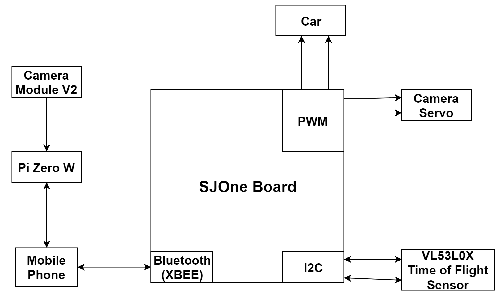
There are various connections to the SJOne Board in the project. To deal with the steering of the car, two different PWM pins are connected to the car: one for the motor and one for the servo. The camera servo also requires two connections to the PWM pins of the SJOne Board: one for the tilt and one for the horizontal movements. The VL53L0X time of flight sensor sends data through the I2C bus to the SJOne Board and requires a connection for the data and another for the clock. To connect to the mobile phone, an XBEE Bluetooth module was placed on the board and it communicates with the microprocessor via UART. Finally, the mobile phone connects to the Raspberry Pi Zero W and camera through a hotspot connection.
Hardware Interface
In this section, you can describe how your hardware communicates, such as which BUSes used. You can discuss your driver implementation here, such that the Software Design section is isolated to talk about high level workings rather than inner working of your project.
Pin Connectivity Table
| Item | Pin Usage | Port.Pin | Direction | Peripheral | Peripheral Port |
|---|---|---|---|---|---|
| 1 | PWM | P2.0 | Output | SJ One Board | Car Motor |
| 2 | PWM | P2.1 | Output | SJ One Board | Car Servo |
| 3 | PWM | P2.2 | Output | SJ One Board | Camera Servo Tilt |
| 4 | PWM | P2.3 | Output | SJ One Board | Camera Servo Horizontal |
| 5 | I2C | SDA2 | Bidirectional | SJ One Board | VL53L0X SDA |
| 6 | I2C | SCL | Bidirectional | SJ One Board | VL53L0X SCL |
| 7 | GPIO | P0.29 | Output | SJ One Board | VL53L0X Shutdown |
| 8 | UART2 | - | Bidirectional | SJ One Board | XBEE Bluetooth |
PWM
Something Something
I2C

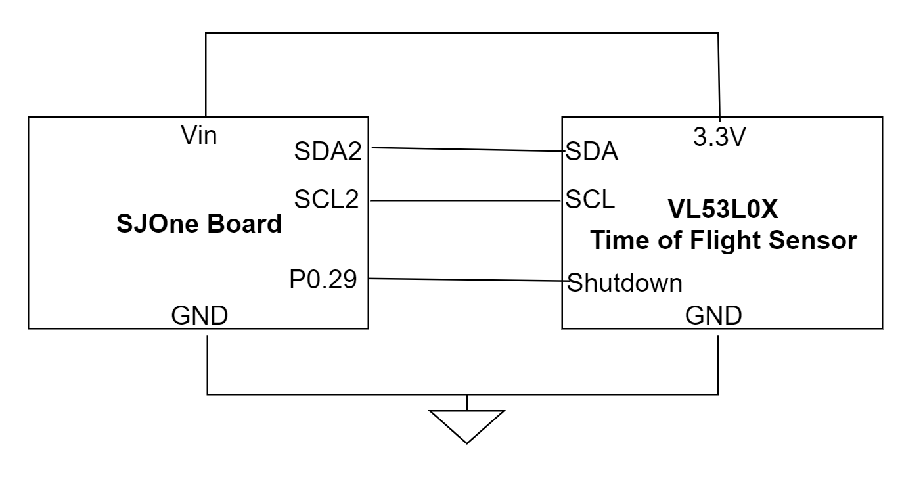
The VL53L0X time of flight sensor connects to the SJOne Board through the I2C Bus. The SDA and SCL signals are connected to the SDA2 and SCL2 pins on the SJOne Board, respectively. In addition, the shutdown pin is connected to P0.29 which is used as an output with the GPIO functionality of the microprocessor.
UART2
Something Something
Software Design
Show your software design. For example, if you are designing an MP3 Player, show the tasks that you are using, and what they are doing at a high level. Do not show the details of the code. For example, do not show exact code, but you may show psuedocode and fragments of code. Keep in mind that you are showing DESIGN of your software, not the inner workings of it.
Implementation
This section includes implementation, but again, not the details, just the high level. For example, you can list the steps it takes to communicate over a sensor, or the steps needed to write a page of memory onto SPI Flash. You can include sub-sections for each of your component implementation.
Servo Motor
The servo motor is used as a camera mount for the Raspberry Pi camera. It uses a PWM signal and the percentage of how much the servo should pan or tilt is supplied by the Android application
Testing & Technical Challenges
Describe the challenges of your project. What advise would you give yourself or someone else if your project can be started from scratch again? Make a smooth transition to testing section and described what it took to test your project.
Include sub-sections that list out a problem and solution, such as:
<Bug/issue name>
Discuss the issue and resolution.
Raspberry Pi Camera Ribbon
The ribbon used for the camera to communicate with the RPi is very sensitive. While testing out the camera and its settings, the video feed would cut out a lot when the ribbon was disturbed. There were times when the camera would not be detected at all. To remedy this issue, the connection was gently redone until the video feed returned.
Connecting to the Pi Zero W
Initially, the group wanted to have the phone to connect to the Raspberry Pi through Wi-Fi. However, when setting up the Pi to be a Wi-Fi host, the phones could not discover the Pi making communication impossible. Furthermore, it did not allow the Pi to initially boot up properly. To rectify this problem, the group decided to have the mobile phone with the application be a hotspot host. While this means that the Pi would have to be reconfigured every time it wants to connect to a new phone, the results would be consistent with the feed from the camera being able to broadcast to the host phone.
Conclusion
Conclude your project here. You can recap your testing and problems. You should address the "so what" part here to indicate what you ultimately learnt from this project. How has this project increased your knowledge?
Project Video
Upload a video of your project and post the link here.
Project Source Code
References
Acknowledgement
- Preetpal Kang
- Khalil Estell
References Used
List any references used in project.
Appendix
You can list the references you used.