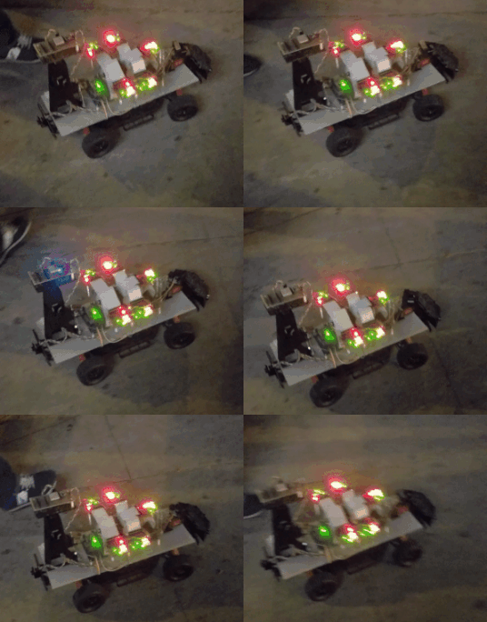
F17: Vindicators100
Contents
Grading Criteria
- How well is Software & Hardware Design described?
- How well can this report be used to reproduce this project?
- Code Quality
- Overall Report Quality:
- Software Block Diagrams
- Hardware Block Diagrams
- Schematic Quality
- Quality of technical challenges and solutions adopted.
Abstract
Objectives & Introduction
Show list of your objectives. This section includes the high level details of your project. You can write about the various sensors or peripherals you used to get your project completed.
Team Members & Responsibilities
- Sameer Azer
- Project Lead
- Sensors
- Quality Assurance
- Kevin Server
- Unit Testing Lead
- Control Unit
- Delwin Lei
- Sensors
- Control Unit
- Harmander Sihra
- Sensors
- Mina Yi
- DEV/GIT Lead
- Drive System
- Elizabeth Nguyen
- Drive System
- Matthew Chew
- App
- GPS/Compass
- Mikko Bayabo
- App
- GPS/Compass
- Rolando Javier
- App
- GPS/Compass
Schedule
Show a simple table or figures that show your scheduled as planned before you started working on the project. Then in another table column, write down the actual schedule so that readers can see the planned vs. actual goals. The point of the schedule is for readers to assess how to pace themselves if they are doing a similar project.
| Sprint | End Date | Plan | Actual |
|---|---|---|---|
| 1 | 10/10 | App(HL reqs, and framework options);
Master(HL reqs, and draft CAN messages); GPS(HL reqs, and component search/buy); Sensors(HL reqs, and component search/buy); Drive(HL reqs, and component search/buy); |
App(Angular?);
Master(Reqs identified, CAN architecture is WIP); GPS(UBLOX M8N); Sensors(Lidar: 4UV002950, Ultrasonic: HRLV-EZ0); Drive(Motor+encoder: https://www.servocity.com/437-rpm-hd-premium-planetary-gear-motor-w-encoder, Driver: Pololu G2 24v21, Encoder Counter: https://www.amazon.com/SuperDroid-Robots-LS7366R-Quadrature-Encoder/dp/B00K33KDJ2); |
| 2 | 10/20 | App(Further Framework research);
Master(Design unit tests); GPS(Prototype purchased component: printf(heading and coordinates); Sensors(Prototype purchased components: printf(distance from lidar and bool from ultrasonic); Drive(Prototype purchased components: move motor at various velocities); |
App(Decided to use ESP8266 web server implementation);
Master(Unit tests passed); GPS(GPS module works, but inaccurate around parts of campus. Compass not working. Going to try new component); Sensors(Ultrasonic works [able to get distance reading over ADC], Lidar doesn't work with I2C driver. Need to modify I2C Driver); Drive(Able to move. No feedback yet.); |
| 3 | 10/30 | App(Run a web server on ESP8266);
Master(TDD Obstacle avoidance); GPS(Interface with compass); Sensors(Interface with Lidar); Drive(Interface with LCD Screen); |
App(web Server running on ESP8266, ESP8266 needs to "talk" to SJOne);
Master(Unit tests passed for obstacle avoidance using ultrasonic); GPS(Still looking for a reliable compass); Sensors(I2C Driver modified. Lidar is functioning. Waiting on Servo shipment and more Ultrasonic sensors); Drive(LCD Driver works using GPIO); |
| 4 | 11/10 | App(Manual Drive Interface, Start, Stop);
Master(Field-test avoiding an obstacle using one ultrasonic and Lidar); GPS(TDD Compass data parser, TDD GPS data parser, Write a CSV file to SD card); Sensors(Interface with 4 Ultrasonics [using chaining], Test power management chip current sensor, voltage sensor, and output on/off, Field-test avoiding an obstacle using 1 Ultrasonic); Drive(Servo library [independent from PWM Frequency], Implement quadrature counter driver); |
App(Cancelled Manual Drive, Start/Stop not finished due to issues communicating with ESP);
Master(Field-test done without Lidar. Master is sending appropriate data. Drive is having issues steering.); GPS(Found compass and prototyping. Calculated projected heading.); Sensors(Trying to interface ADC MUX with the ultrasonics. Integrating LIDAR with servo); Drive(Done.); |
| 5 | 11/20 | App(Send/receive GPS data to/from App);
Master(Upon a "Go" from App, avoid multiple obstacles using 4 ultrasonics and a rotating lidar); GPS(TDD Compass heading and error, TDD GPS coordinate setters/getters, TDD Logging); Sensors(CAD/3D-Print bumper mount for Ultrasonics, CAD/3D-Print Lidar-Servo interface. Servo-Car interface); Drive(Implement a constant-velocity PID, Implement a PID Ramp-up functionality to limit in-rush current); |
App(Google map data point acquisition, and waypoint plotting);
Master(State machine set up, waiting on app); GPS(Compass prototyping and testing using raw values); Sensors(Working on interfacing Ultrasonic sensors with ADC mux. Still integrating LIDAR with the servo properly); Drive(Completed PID ramp-up, constant-velocity PID incomplete, but drives.); |
| 6 | 11/30 | App(App-Nav Integration testing: Send Coordinates from App to GPS);
Master(Drive to specific GPS coordinates); GPS(App-Nav Integration testing: Send Coordinates from App to GPS); Sensors(Field-test avoiding multiple obstacles using Lidar & Ultrasonics); Drive(Interface with buttons and headlight); |
App(SD Card Implementation for map data point storage; SD card data point parsing);
Master(waiting on app and nav); GPS(live gps module testing, and risk area assessment, GPS/compass integration); Sensors(Cleaning up Ultrasonic readings coming through the ADC mux. Troubleshooting LIDAR inaccuracy); Drive(Drive Buttons Interfaced. Code refactoring complete.); |
| 7 | 12/10 | App(Full System Test w/ PCB);
Master(Full System Test w/ PCB); GPS(Full System Test w/ PCB); Sensors(Full System Test w/ PCB); Drive(Full System Test w/ PCB); |
App(Full system integration testing with PCB);
Master(Done); GPS(Full system integration testing with PCB); Sensors(LIDAR properly calibrated with accurate readings); Drive(Code Refactoring complete. No LCD or Headlights mounted on PCB.); |
| 8 | 12/17 | App(Full System Test w/ PCB);
Master(Full System Test w/ PCB); GPS(Full System Test w/ PCB); Sensors(Full System Test w/ PCB); Drive(Full System Test w/ PCB); |
App(Fine-tuning and full system integration testing with ESP8266 webserver);
Master(Done); GPS(Final Pathfinding Algorithm Field-Testing); Sensors(Got Ultrasonic sensors working with ADC mux); Drive(Missing LCD and Headlights on PCB.); |
Parts List & Cost
| Part # | Part Name | Purchase Location | Quantity | Cost per item |
|---|---|---|---|---|
| 1 | SJOne Board | Preet | 5 | $80/board |
| 2 | 1621 RPM HD Premium Gear Motor | Servocity | 1 | $60 |
| 3 | 20 kg Full Metal Servo | Amazon | 1 | $18.92 |
| 4 | Maxbotix Ultrasonic Rangefinder | Adafruit | 4 | $33.95 |
| 5 | Analog/Digital Mux Breakout Board | RobotShop | 1 | $4.95 |
| 6 | EV-VN7010AJ Power Management IC Development Tools | Mouser | 1 | $8.63 |
| 7 | eBoot Mini MP1584EN DC-DC Buck Converter | Amazon | 2 | $9.69 |
| 8 | Garmin Lidar Lite v3 | SparkFun | 1 | $150 |
| 9 | ESP8266 | Amazon | 1 | $8.79 |
| 10 | Savox SA1230SG Monster Torque Coreless Steel Gear Digital Servo | Amazon | 1 | $77 |
| 11 | Lumenier LU-1800-4-35 1800mAh 35c Lipo Battery | Amazon | 1 | $34 |
| 12 | Acrylic Board | Tap Plastics | 2 | $1 |
| 13 | Pololu G2 High-Power Motor Driver 24v21 | Pololu | 1 | $40 |
| 14 | Hardware Components (standoffs, threaded rods, etc.) | Excess Solutions, Ace | - | $20 |
| 15 | LM7805 Power Regulator | Mouser | 1 | $0.90 |
| 16 | Triple-axis Accelerometer+Magnetometer (Compass) Board - LSM303 | Adafruit | 1 | $14.95 |
Design & Implementation
Hardware Design
In this section, we provide details on hardware design for each component - power management, drive, sensors, app, and GPS.
Power Management
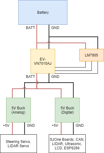
We used an EV-VN7010AJ Power Management Board to monitor real-time battery voltage. The power board has a pin which outputs a current proportional to the battery voltage. Connecting a load resistor between this pin and ground gives a smaller voltage proportional to the battery voltage. We read this smaller voltage using the ADC pin on the SJOne Board.
From battery voltage, it is split up into two 5V rails, an analog 5V (for the servos) and a digital 5V (for boards, transceivers, LIDAR, US sensors, etc.). We're using two buck converters to step the voltage down from battery voltage. There is also a battery voltage rail which goes to the drive system, which they then PWM to get their desired voltage level.
There is also an LM7805 regulator which is used just to power some of the power management chip's control signals.
Drive
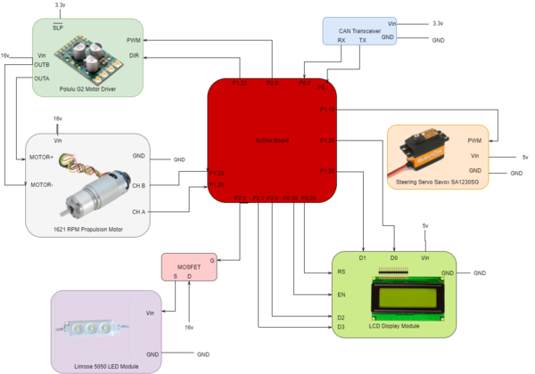
| The hardware components for drive consists of the motor driver, the servo for steering, and the motor.
Our drive system contains the following hardware components:
The motor driver is powered by our battery (about 16v). It takes in a PWM signal from the SJOne board. It also has a control signal, SLP, which is active low and it is tied high from the 3.3v power rail. The motor driver outputs two signals OUTA and OUTB used to control the propulsion motor which outputs signals for CH A and CH B to the SJOne board. It is also powered by our 16v battery. The steering servo is controlled by the SJOne board via PWM and requires a 5v input. The headlights use a MOSFET where the drain is connected to the 16v battery. The gate is a PWM signal input from the SJOne board which outputs at source, to the LED module's Vin. Lastly, the LCD display requires a 5v input and has two control signals, EN and RS. It receives inputs from the SJOne board via GPIO for D0-D3 pins to display items on the LCD screen. |
Sensors
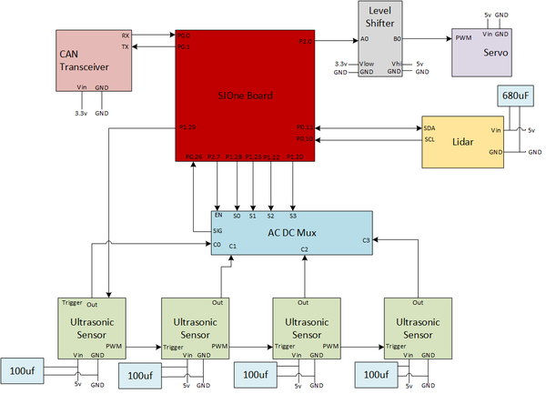
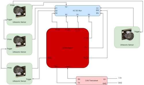
We are using two sets of sensors - a LIDAR and 4 ultrasonic sensors.The Sensors System Hardware Design provides an overview of the entire sensors system and its connections.
LIDAR
|
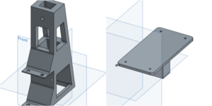
Our LIDAR system has two main separate hardware components - the LIDAR and the servo. The LIDAR is connected to the SJOne board using the i2c2 pins (P0.10 & P0.11). To mount the LIDAR onto the servo, a case that holds the LIDAR and an actual mounting piece was designed and printed using a 3D printer. The Lidar System and Mount Diagrams shows the three components for mounting the lidar to the servo and then to the car. The top image is a diagram of our hardware components and connections to the SJOne board. The bottom three images show the following:
|
Ultrasonic Sensors
|
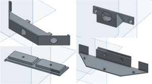
The ultrasonic sensor setup that we have installed on the autonomous car is three ultrasonic sensors on the front and one on the back. The layout of the front sensors is one sensor down the middle and one on each side angled at 26.4/45 degrees. All sensors are daisy chained together with the initial sensor triggered by a GPIO pin, A mount for all the ultrasonic sensors was designed and 3D printed. In the CAD Design for Ultrasonic Sensor Mount the top right component is used for the rear sensor while the remaining three are combined to create the front holding mount that is attached to the front of our car. |
App
|
Our application uses an ESP8266 as our bridge for wifi connectivity. The ESP8266 takes an input voltage of 5v which is connected to the 5v digital power rail. The ESP8266's RX is connected to the TXD2 pin on the SJOne board and the TX is connected to the RXD2 on the SJOne board for UART communication. As with all other components, we are using CAN for communication between the boards and so it uses |
GPS
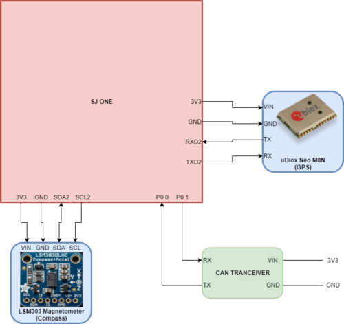
Our GPS system uses the following:
The uBlock Neo uses UART for communication so the TX is connected to the SJOne's RXD2 pin and the RX is connected to the TXD2 pin. The module is powered directly from the SJOne board using the onboard 3.3v output pin which has been connected to a 3.3v power rail to supply power to other modules. The LSM303 magnetometer module uses i2c for communication. The SDA is connected to the SJOne's SDA2 pin and the SCL is connected to the SJOne's SCL2 pin. The LSM303 also needs 3.3v to be powered and it is also connected to the 3.3v power rail. |
Hardware InterfaceIn this section we provide details on the hardware interfaces used for each system. Power ManagementThe EV-VN7010AJ has a very basic control control mechanism. It has an output enable pin, MultiSense enable pin, and MultiSense multiplexer select lines. All of the necessary pins are either permanently tied to +5V, GND, or a GPIO pin on the SJOne Board. The MultiSense pin outputs information about the current battery voltage. The MultiSense pin is simply connected to an ADC pin on the SJOne board. DriveThe drive system is comprised of two main parts - the motor driver and propulsion motor and the steering servo. We provide information about each of these component's hardware interfaces. Motor Driver & Propulsion MotorThe motor driver is used to control the propulsion motor via OUTA and OUTB. It is driven by the SJOne board using a PWM signal connected to pin Steering ServoOur steering servo is driven via a PWM signal as well. The PWM frequency is set to 50 Hz. However, since we are already using a PWM signal for the motor, we used a repetitive interrupt timer (RIT) to manually generate a PWM signal using a GPIO pin for the steering servo.
The RIT had to be modified to allow us to count in microseconds (uS) since the original only allows to count in ms.
To do this, we added an additional parameter For example, we wanted to trigger our callback every 50 us. Thus, our prefix is 1000000 (amount of us in 1 second) and our time is 50 (us). This will give us the number of 50 us in 1 second in terms of us, which is 20000. When we take our system clock (48 MHz) and divide it by the number we just calculated and it gives us the number of CPU cycles we want before the callback is triggered. // function prototype
void rit_enable(void_func_t function, uint32_t time, uint32_t prefix);
// Enable RIT - function, time, prefix
rit_enable(RIT_PWM, RIT_INCREMENT_US, MICROSECONDS);
// modified calculation
LPC_RIT->RICOMPVAL = sys_get_cpu_clock() / (prefix / time);We used pin
NOTE Our target has to be in terms of us since all of our calculations are in us. We get the target for our RIT by obtaining a target angle from control. We use a mapping function to generate our target in us from the desired angle. The initial value for the mapping function calculation was done by using a function generator with our steering servo.
We were then able to generate a simple mapping function to map angles in degrees to us using:
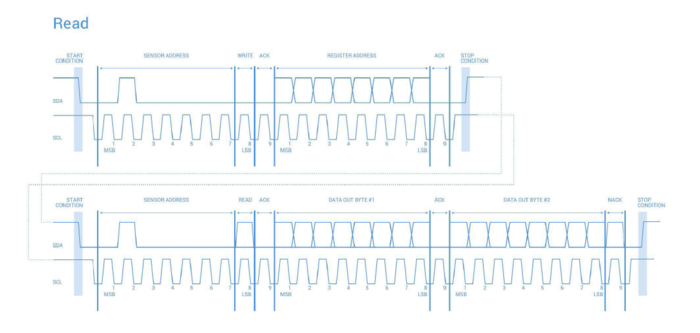
LCD ScreenThe LCD screen was interfaced with the SJOne board using a variety of GPIO pins for data (D0, D1, D2, D3) and to enable the screen (EN). HeadlightsOur driver for the headlights uses pin SensorsUltrasonic Sensor InterfaceThere are two mounting brackets for our ultrasonic sensors; one angled at 26.4 degrees and another at 45 degrees. The mounting brace on the front bumper of the autonomous car allows us to install either brackets based on our desired functionality. The ultrasonic sensors are also interfaced with an ADC mux because the SJOne board does not have enough ADC pins to process our sensors individually. Lidar and Servo InterfaceThe lidar communicates via i2c. Typically, when executing a read operation, there is a write and then a read. It writes the device address and provides a repeat start. However, the lidar expects a stop signal and does not respond to a repeat start, as shown in the Lidar Read Timing Diagram. Thus, we utilized a modified version of the i2c driver that does two completely separate write and read operations. This provides the proper format expected by the lidar. The lidar driver is as follows:
lidar_i2c2 = &I2C2::getInstance();
lidar_i2c2->writeReg((DEVICE_ADDR << 1), ACQ_COMMAND, 0x00);
lidar_servo = new PWM(PWM::pwm1, SERVO_FREQUENCY);
Initialize lidar to default configuration // set configuration to default for balanced performance
lidar_i2c2->writeReg((DEVICE_ADDR << 1), 0x02, 0x80);
lidar_i2c2->writeReg((DEVICE_ADDR << 1), 0x04, 0x08);
lidar_i2c2->writeReg((DEVICE_ADDR << 1), 0x1c, 0x00);
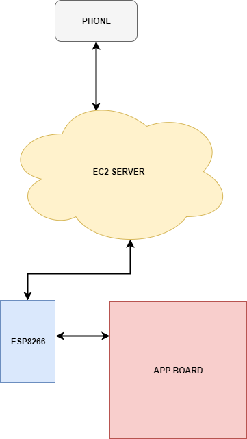
return (bytes[0] << 8) | bytes[1];The driver for the servo simply uses the PWM functions from the library provided to us to initialize the PWM signal to our desired frequency. In our case, we used a 50Hz signal. We also used the GPSThe GPS (uBlox NEO M8N) uses UART to send GPS information. We've disabled all messages except for $GNGLL, which gives us the current coordinates of our car. The GPS then sends parse-able lines of text over its TX pin that contains the latitude, longitude, and UTC. The SJOne board receives this text via RXD2 (Uart2). The GPS can be configured by sending configuration values over its RX pin. To do this, we send configurations over the SJOne's TXD2 pin and save the configuration by sending a save command to the GPS. CompassWe made a compass using the LSM303 Magnetometer. To do this, we first had to configure the mode register to allow for continuous reads. We also had to set the gain by modifying the second configuration register. The compass can then be polled at 10Hz to read the X, Y, and Z registers, which are comprised of 6 1-byte wide registers. From this, we can calculate the heading by atan2(Y,X). We chose to completely neglect the Z axis as we found that it made very little difference for our project. Software DesignIn this section we provide details on our software design for each of the systems. We also delve into our DBC file and the messages sent via CAN bus. APP BOARD / ESP8266 / Server / Phone CommunicationThe Phone communicates to the server via a website. The website was created with the Django Web Framework. Commands from the phone are saved in a database that the ESP8266 and APP Board can poll. The APP board sends a command to read a specific URL. For instance, the APP board can send "http://exampleurl.com/commands/read/" to the ESP8266. The ESP8266 will make a GET request to the server to see if there are any commands it needs to execute. If it finds one, it will send that information over UART to the APP board. To send from the APP to the server, the APP board sends a URL to the ESP8266 such as "http://exampleurl.com/nav/update_heading/?current_heading=0&desired_heading=359". The ESP8266 makes a GET request so that the server can update the current and desired headings. CAN Communication243.dbc VERSION ""
NS_ :
BA_
BA_DEF_
BA_DEF_DEF_
BA_DEF_DEF_REL_
BA_DEF_REL_
BA_DEF_SGTYPE_
BA_REL_
BA_SGTYPE_
BO_TX_BU_
BU_BO_REL_
BU_EV_REL_
BU_SG_REL_
CAT_
CAT_DEF_
CM_
ENVVAR_DATA_
EV_DATA_
FILTER
NS_DESC_
SGTYPE_
SGTYPE_VAL_
SG_MUL_VAL_
SIGTYPE_VALTYPE_
SIG_GROUP_
SIG_TYPE_REF_
SIG_VALTYPE_
VAL_
VAL_TABLE_
BS_:
BU_: DBG SENSORS CONTROL_UNIT DRIVE APP NAV
BO_ 100 COMMAND: 1 DBG
SG_ ENABLE : 0|1@1+ (1,0) [0|1] "" DBG
BO_ 200 ULTRASONIC_SENSORS: 6 SENSORS
SG_ front_sensor1 : 0|12@1+ (1,0) [0|0] "cm" CONTROL_UNIT,APP,DRIVE
SG_ front_sensor2 : 12|12@1+ (1,0) [0|0] "cm" CONTROL_UNIT,APP,DRIVE
SG_ front_sensor3 : 24|12@1+ (1,0) [0|0] "cm" CONTROL_UNIT,APP,DRIVE
SG_ back_sensor1 : 36|12@1+ (1,0) [0|0] "cm" CONTROL_UNIT,APP,DRIVE
BO_ 101 LIDAR_DATA1: 7 SENSORS
SG_ lidar_data1 : 0|11@1+ (1,0) [0|0] "cm" CONTROL_UNIT,APP
SG_ lidar_data2 : 11|11@1+ (1,0) [0|0] "cm" CONTROL_UNIT,APP
SG_ lidar_data3 : 22|11@1+ (1,0) [0|0] "cm" CONTROL_UNIT,APP
SG_ lidar_data4 : 33|11@1+ (1,0) [0|0] "cm" CONTROL_UNIT,APP
SG_ lidar_data5 : 44|11@1+ (1,0) [0|0] "cm" CONTROL_UNIT,APP
BO_ 102 LIDAR_DATA2: 6 SENSORS
SG_ lidar2_data6 : 0|11@1+ (1,0) [0|0] "cm" CONTROL_UNIT,APP
SG_ lidar2_data7 : 11|11@1+ (1,0) [0|0] "cm" CONTROL_UNIT,APP
SG_ lidar2_data8 : 22|11@1+ (1,0) [0|0] "cm" CONTROL_UNIT,APP
SG_ lidar2_data9 : 33|11@1+ (1,0) [0|0] "cm" CONTROL_UNIT,APP
BO_ 123 DRIVE_CMD: 3 CONTROL_UNIT
SG_ steer_angle : 0|9@1- (1,0) [-23|23] "degrees" DRIVE,APP
SG_ speed : 9|6@1+ (1,0) [0|20] "mph" DRIVE,APP
SG_ direction : 15|1@1+ (1,0) [0|1] "" DRIVE,APP
SG_ headlights : 16|1@1+ (1,0) [0|1] "" DRIVE,APP
BO_ 122 SENSOR_CMD: 1 CONTROL_UNIT
SG_ lidar_zero : 0|8@1- (1,0) [-90|90] "degrees" SENSORS,APP
BO_ 121 GPS_POS: 8 NAV
SG_ latitude : 0|32@1+ (0.000001,-90) [-90|90] "degrees" APP
SG_ longitude : 32|32@1+ (0.000001,-180) [-180|180] "degrees" APP
BO_ 120 GPS_STOP: 1 NAV
SG_ stop : 0|1@1+ (1,0) [0|1] "" APP,CONTROL_UNIT
BO_ 119 GPS_STOP_ACK: 1 CONTROL_UNIT
SG_ stop_ack : 0|1@1+ (1,0) [0|1] "" APP,NAV
BO_ 148 LIGHT_SENSOR_VALUE: 1 SENSORS
SG_ light_value : 0|8@1+ (1,0) [0|100] "%" CONTROL_UNIT,APP
BO_ 146 GPS_HEADING: 3 NAV
SG_ current : 0|9@1+ (1,0) [0|359] "degrees" APP,CONTROL_UNIT
SG_ projected : 10|9@1+ (1,0) [0|359] "degrees" APP,CONTROL_UNIT
BO_ 124 DRIVE_FEEDBACK: 1 DRIVE
SG_ velocity : 0|6@1+ (0.1,0) [0|0] "mph" CONTROL_UNIT,APP
SG_ direction : 6|1@1+ (1,0) [0|1] "" CONTROL_UNIT,APP
BO_ 243 APP_DESTINATION: 8 APP
SG_ latitude : 0|32@1+ (0.000001,-90) [-90|90] "degrees" NAV
SG_ longitude : 32|32@1+ (0.000001,-180) [-180|180] "degrees" NAV
BO_ 244 APP_DEST_ACK: 1 NAV
SG_ acked : 0|1@1+ (1,0) [0|1] "" APP
BO_ 245 APP_WAYPOINT: 2 APP
SG_ index : 0|7@1+ (1,0) [0|0] "" NAV
SG_ node : 7|7@1+ (1,0) [0|0] "" NAV
BO_ 246 APP_WAYPOINT_ACK: 1 NAV
SG_ index : 0|7@1+ (1,0) [0|0] "" APP
SG_ acked : 7|1@1+ (1,0) [0|1] "" APP
BO_ 0 APP_SIG_STOP: 1 APP
SG_ APP_SAYS_stop : 0|8@1+ (1,0) [0|1] "" CONTROL_UNIT
BO_ 2 APP_SIG_START: 1 APP
SG_ APP_SAYS_start : 0|8@1+ (1,0) [0|1] "" CONTROL_UNIT
BO_ 1 STOP_SIG_ACK: 1 CONTROL_UNIT
SG_ control_received_stop : 0|8@1+ (1,0) [0|1] "" APP
BO_ 3 START_SIG_ACK: 1 CONTROL_UNIT
SG_ control_received_start : 0|8@1+ (1,0) [0|1] "" APP
BO_ 69 BATT_INFO: 2 SENSORS
SG_ BATT_VOLTAGE : 0|8@1+ (0.1,0) [0.0|25.5] "V" APP,DRIVE
SG_ BATT_PERCENT : 8|7@1+ (1,0) [0|100] "%" APP,DRIVE
CM_ BU_ DBG "Debugging entity";
CM_ BU_ DRIVE "Drive System";
CM_ BU_ SENSORS "Sensor Suite";
CM_ BU_ APP "Communication to mobile app";
CM_ BU_ CONTROL_UNIT "Central command board";
CM_ BU_ NAV "GPS and compass";
BA_DEF_ "BusType" STRING ;
BA_DEF_ BO_ "GenMsgCycleTime" INT 0 0;
BA_DEF_ SG_ "FieldType" STRING ;
BA_DEF_DEF_ "BusType" "CAN";
BA_DEF_DEF_ "FieldType" "";
BA_DEF_DEF_ "GenMsgCycleTime" 0;
BA_ "GenMsgCycleTime" BO_ 256 10;
BA_ "GenMsgCycleTime" BO_ 512 10;
BA_ "GenMsgCycleTime" BO_ 768 500;
BA_ "GenMsgCycleTime" BO_ 1024 100;
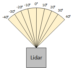
BA_ "GenMsgCycleTime" BO_ 1280 1000;Power ManagementThe MultiSense pin on the EV-VN7010AJ board outputs real time voltage information. It's connected to an ADC pin on the SJOne Board.The ADC reading is converted in software from a 0-4095 range to the actual voltage. DriveThe drive software is separated into 3 main sections: period callbacks, drive methods, and LCD library. The period callback file contains the drive controllers, LCD interface, and message handling. The CAN messages are decoded in the 100 Hz task to feed the desired target values into the PID propulsion controller and the servo steering controller. In addition, the control unit CAN message will control the on and off state of the headlights. The drive methods files contain all functions, classes, and defines necessary for the drive controllers. For example, unit conversion factors and unit conversion functions. The LCD library contains the LCD display driver and high-level functions to interface with a 4x20 LCD display in 4-bit mode. Ultrasonic SensorsFor our software design, we set our TRIGGER pin to high to initiate the first ultrasonic to begin sampling. The ultrasonic sensor trigger requires a high for uqat least 20us and needs to be pulled low before the next sampling cycle. We chose to put a vTaskDelay(10) before pulling the trigger pin low. After pulling the pin low, we wait for an additional 50ms for the ultrasonic sensor to finish sampling and output the correct values for the latest reading. Because we have an ADC mux, we have two GPIOs responsible for selecting which ultrasonic sensor we are reading from. Since we have 4 sensors, we cycle between 00 -> 11 and read from the ADC pin P0,26. For filtering, we are doing an average with a sample size of 50. LIDAROur Lidar class contains a reference to the instance of the PWM class (for the servo) and to the I2C2 class (for communication with the lidar). It also contains an array with 9 elements to hold each of the measurements obtained during the 90° sweep. During development, we found that the lidar takes measurements far faster than the servo can turn. Thus, we had to add a delay long enough for the servo to position itself before obtaining readings. To accomplish this, we created a separate task for the lidar itself called The basic process for the lidar is that it sweeps across a 90° angle right in front of it, as shown in the Lidar Position Diagram. We have a set list of 9 duty cycles for each position we wish to obtain values for. The duty cycles were obtained by calculating the time in ms needed to move 10°. This is covered in further detail in the Implementation section. The basic algorithm is as follows:
Control UnitThe control unit does the majority of its work in the 10Hz periodic task. The 1Hz task is used to check for CAN bus off and to toggle the control unit's heartbeat LED. The 100Hz task is used exclusively for decoding incoming CAN messages and MIA handling. The 10Hz and 100Hz tasks employ a state machine which are both controlled by the STOP and GO messages from APP. If APP sends a GO signal, the state machine will switch to the "GO" state. If APP sends a STOP signal, the state machine will switch to the "STOP_STATE" state. While in the "STOP_STATE" state, the program will simply wait for a GO signal from app. While in the "GO" state, the 10Hz task will perform the path finding, object avoidance, speed, and headlight logic and the 100Hz task will begin decoding incoming CAN messages. Path FindingFor path finding, NAV sends CONTROL_UNIT two headings: projected and current. Projected heading is the heading the car needs to be facing in order to be pointed directly at the next waypoint. Current heading the direction the car is pointing at that moment. These two values are used to determine which direction and of what severity to turn.
Object AvoidanceObject avoidance is broken into multiple steps:
SpeedBecause the maximum speed of our car is about 2mph, speed modulation is relatively simple and can be simplified into stop, slow, and full speed. When lidar detects something is "getting close", the speed will be "slow". The speed will also be set to slow when the car is performing a turn or reversing. If all ultrasonic sensors are blocked (including the rear sensor), the car will stop. HeadlightsIf the light value received from SENSORS is below XXXXXXXXX then CONTROL will send a signal to drive to turn on the headlights. ImplementationThis section includes implementation, but again, not the details, just the high level. For example, you can list the steps it takes to communicate over a sensor, or the steps needed to write a page of memory onto SPI Flash. You can include sub-sections for each of your component implementation.
Testing & Technical ChallengesDescribe the challenges of your project. What advise would you give yourself or someone else if your project can be started from scratch again? Make a smooth transition to testing section and described what it took to test your project. Include sub-sections that list out a problem and solution, such as: Technical ChallengesSingle frequency setting for PWMUsing PWM on the SJOne board only allows you to run all PWM pins at the same frequency. For drive, we required two different frequencies - one for the motor and one for the servo. We solved this issue by generating our own PWM signal using a GPIO pin and a RIT (repetitive interrupt timer). Inaccurate PWM FrequencyWhen originally working with PWM for drive, we found that the actual frequency that was set was inaccurate. We expected the frequency to be 20kHz, but when we hooked it up to the oscilloscope we found that it was much higher. It was consistently setting the frequency to output about 10 times the expected value. We came to the realization that since we had been declaring the PWM class as a global, the initialization was not being done properly. We are not sure why this is the case, but after we instantiated the PWM class in the periodic init function, the frequency was correct. Difficulties with Quadrature CounterWe had issues getting the quadrature counter to give us valid numbers. Our solution was to use LPC's built-in counter instead of having an extra external component. Finding Closest Node from Start PointThe path-finding algorithm requires the car to find the closest node before it can start the route. However, if the closest node is across a building, the car will attempt to drive through buildings to get to that node. We fixed this by adding more nodes such that the closest node will never be across a building. ConclusionConclude your project here. You can recap your testing and problems. You should address the "so what" part here to indicate what you ultimately learnt from this project. How has this project increased your knowledge? Project VideoUpload a video of your project and post the link here. Project Source CodeReferencesAcknowledgementAny acknowledgement that you may wish to provide can be included here. References UsedAPPDjango Web Framework Documentation LSM303 Datasheet SJONEAppendixYou can list the references you used. |
