F17: Viserion
Contents
Viserion Team RC Car
Abstract
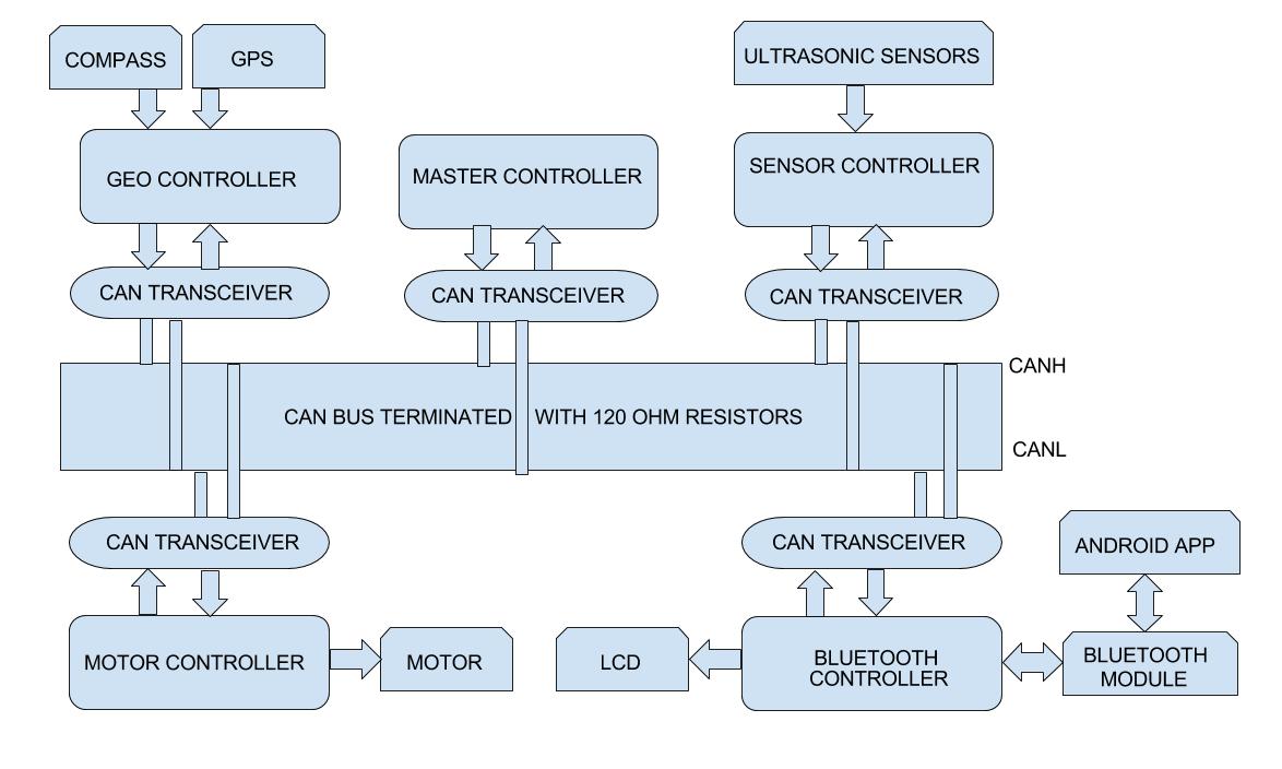
Aim of this project is to build a self-navigating car. The car is divided into five modules. Each module consists of SJ One board as the main controller. The different modules in the car are master, sensors, geo, motor and bluetooth module. The car uses CAN communication protocol for communication between the modules.
The five modules of the car are :
Sensor Controller: This module detects obstacles in the driving path with the help of ultrasonic sensors.
Motor Controller: This controller drives the DC motor and Servo in the car.
Geographical Controller: This module assists the car in navigating to a destination with the help of location details provided by GPS and the orientation(bearing and heading angle) provided by the compass.
Bluetooth Controller: The controller uses Bluetooth to communicate with an Android application. Destination coordinates are provided by this module. The bluetooth module also displays important data like sensor readings, GPS coordinates and speed.
Master Controller: This module will collect data from all modules and direct the motor towards the destination.
Objectives & Introduction
Objectives
The objectives are as follows:
1.To detect and avoid obstacles encountered in the path.
2.To move at an appropriate speed depending upon the path requirement.
3.To use Bluetooth module to start/stop the car and display important data on the LCD.
4.To integrate gps and compass to make sure that the car navigates from source to destination.
5.To efficiently establish communication between all the modules using CAN protocol.
6.To reach a destination given by the Bluetooth module autonomously for a valid path.
System Block Diagram
Team Members & Responsibilities
Master Controller
- Aakash Menon
- Omkar Kale
Geographical Controller
- Ajinkya Mandhre
- Aniket Dali
- Jean Madassery
Sensor Controller
MOTOR & I/O CONTROLLER
- Manoj Ramesh Rao
- Pratap Ramachandran
BLUETOOTH CONTROLLER & ANDROID APP
- Dheemanth Bangalore Vishwanatha
- Pratap Kishore Desai
Schedule
Show a simple table or figures that show your scheduled as planned before you started working on the project. Then in another table column, write down the actual schedule so that readers can see the planned vs. actual goals. The point of the schedule is for readers to assess how to pace themselves if they are doing a similar project.
Legend: Motor & I/O Controller , Master Controller , Communication Bridge Controller, Geographical Controller, Sensor Controller , Team Goal , Team PCB, , Team Android
| Week# | Start Date | End Date | Task | Actual Completion Date / Notes | Status |
|---|---|---|---|---|---|
| 1 | 10/09/2017 | 10/15/2017 |
|
Done | |
| 2 | 10/16/2017 | 10/22/2017 |
|
Done on time except
|
|
| 3 | 10/23/2017 | 29/10/2017 |
|
Done on time except
|
|
| 4 | 10/30/2017 | 11/05/2017 |
|
Done on time | |
| 5 | 11/06/2017 | 11/12/2017 |
|
|
|
| 6 | 11/13/2017 | 11/19/2017 |
|
|
|
| 7 | 11/20/2017 | 11/25/2017 |
|
|
|
| 8 | 11/26/2017 | 12/01/2017 |
|
|
|
| 9 | 12/03/2017 | 12/08/2017 |
|
||
| 10 | 12/10/2017 | 12/12/2017 |
|
||
| 11 | 12/13/2017 | 12/16/2017 |
|
||
| 12 | 12/17/2017 | 12/19/2017 |
|
||
| 13 | 12/20/2017 |
|
Parts List & Cost
| Item# | Part Desciption | Vendor | Qty | Cost |
|---|---|---|---|---|
| 1 | RC Car - Traxxas 1/10 Slash 2WD | Amazon | 1 | $189.95 |
| 2 | Battery - Traxxas 7600mAh 7.4V 2-Cell 25C LiPo Battery | Amazon | 2 | $143.26 |
| 3 | Charger - Traxxas 2970 EZ-Peak Plus 4-Amp NiMH/LiPo Fast Charger | Amazon | 1 | $49.95 |
| 4 | GPS - Readytosky Ublox NEO-M8N GPS Module | Amazon | 1 | $29.98 |
| 5 | Bluetooth Module HC-05 | Amazon | 1 | $8.99 |
| 6 | IMU SparkFun 9DoF Razor IMU M0 | SparkFun | 1 | $49.95 |
| 7 | LV Maxsonar EZ0 Ultrasonic sensors | Robotshop | 6 | $158.7 |
| 8 | RPM Sensor - Traxxas 6520 RPM Sensor | Amazon | 1 | $10.25 |
| 9 | Jumper Wires | Amazon | 1 | $10 |
| 10 | Acrylic Board MIFFLIN Acrylic Plexiglass 12 x 12 | Amazon | 1 | $11 |
| 11 | CAN tranceivers | Microchip Samples | 30 | Free |
| 12 | SJOne Boards | Provided by Preet | 5 | $400.0 |
Design & Implementation
Motor and I/O Controller
The motor controller is responsible for the steering and controlling the speed of the car. Both direction and speed of the car is controlled using the duty cycle of PWM signal. The speed of the car can be controlled by sending appropriate signals to the ESC connected to the DC motor of the car.
Hardware Design
Discuss your hardware design here. Show detailed schematics, and the interface here.
Hardware Interface
In this section, you can describe how your hardware communicates, such as which BUSes used. You can discuss your driver implementation here, such that the Software Design section is isolated to talk about high-level workings rather than the inner working of your project.
DC Motor
ESC
Servo
RPM Sensor
Software Design
Show your software design. For example, if you are designing an MP3 Player, show the tasks that you are using, and what they are doing at a high level. Do not show the details of the code. For example, do not show exact code, but you may show pseudocode and fragments of code. Keep in mind that you are showing DESIGN of your software, not the inner workings of it.
Steering Control
Speed Control
Consistent speed based on feedback
The design section can go over your hardware and software design. Organize this section using sub-sections that go over your design and implementation.
Implementation
This section includes implementation, but again, not the details, just the high level. For example, you can list the steps it takes to communicate over a sensor, or the steps needed to write a page of memory onto SPI Flash. You can include sub-sections for each of your component implementation.
Master Controller
The master controller is the brain of the car. It communicates over CAN bus with other modules to receive data. It accepts the values of different sensors mounted in front and rear, and takes decision based on this data. It uses heartbeat mechanisms to keep a check on other modules in the system. The entire module has two main algorithms : one for Obstacle Avoidance and another for Navigation.
Hardware Design
This module was interfaced with Microchip CAN transceiver MCP2551 to communicate with other nodes in the bus. No external peripherals were connected to the master controller.
The figure below shows the hardware design of the master.
Software Design
Obstacle Avoidance
Directions And Steering Signals
Testing Challenges
Testing
Technical Challenges
Implementation
Bluetooth Controller And Android Application
Design And Implementation
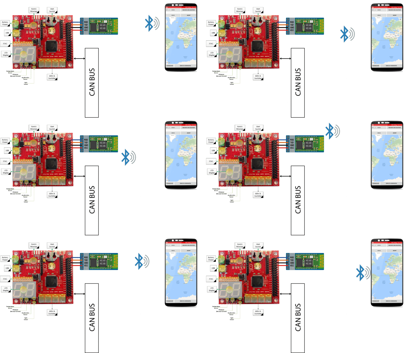
The user selects a destination on the android application which then communicates with the Bluetooth module HC-05 through which car gets to know the route to destination. The user can directly interact with the car using the android application so this is one of the most important modules. The detailed software and hardware design is mentioned in below sub sections.
Hardware Design
This includes
• SJ-One Board
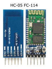
• Bluetooth Module HC-05
• Android Smartphone
• CAN transceiver
Bluetooth Module
Specifications
• Bluetooth protocol: Bluetooth Specification v2.0+EDR
• Frequency: 2.4GHz ISM band
• Speed: Asynchronous: 2.1Mbps(Max) / 160 kbps, Synchronous: 1Mbps/1Mbps
• Profiles: Bluetooth serial port
• Power supply: +3.3VDC 50mA
• Working temperature: -20 ~ +75Centigrade
• Dimension: 26.9mm x 13mm x 2.2 mm
• Modulation: GFSK(Gaussian Frequency Shift Keying)
• Sensitivity: ≤-84dBm at 0.1% BER
• Security: Authentication and encryption
Bluetooth And SJOne Board Connection Diagram
Hardware Interface
The Bluetooth module HC05 is connected to Bluetooth-ECU using UART3. The transmission rate is 9600bps. Bluetooth-ECU communicates with all other ECU's using CAN-Transceiver.The following pins where used for connections.
Bluetooth-ECU
| Function On ECU | Pin NO On ECU | Function On HC05 |
|---|---|---|
| RX | P4_28 | TX |
| TX | P4_29 | RX |
Software Design
Bluetooth Module
Android Application
Implementation
Testing
Technical Challenges
Testing & Technical Challenges
Describe the challenges of your project. What advise would you give yourself or someone else if your project can be started from scratch again? Make a smooth transition to testing section and described what it took to test your project.
Include sub-sections that list out a problem and solution, such as:
<Bug/issue name>
Discuss the issue and resolution.
Conclusion
Conclude your project here. You can recap your testing and problems. You should address the "so what" part here to indicate what you ultimately learnt from this project. How has this project increased your knowledge?
Project Video
Upload a video of your project and post the link here.
Project Source Code
References
Acknowledgement
Any acknowledgement that you may wish to provide can be included here.
References Used
List any references used in project.
Appendix
You can list the references you used.


