S17: CamBot
Contents
CamBot
Abstract
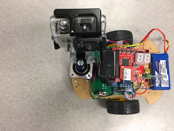
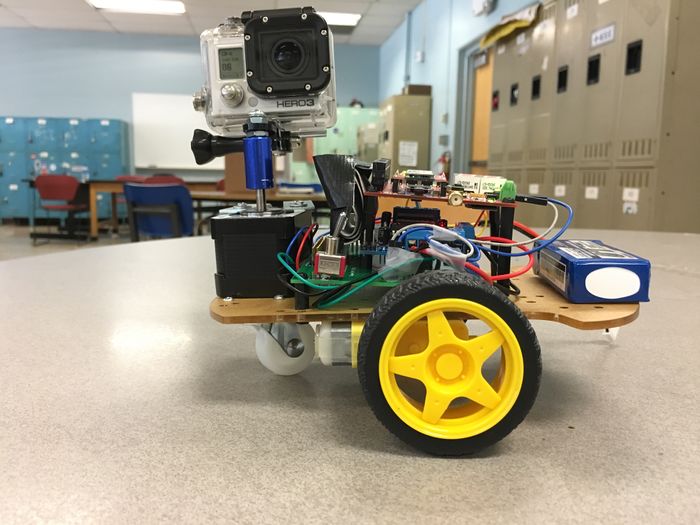
It is often observed that photographers capturing time-lapses require specific set of motions of the camera. Automating these motions would be beneficial as they eliminate manual intervention and allow the photographer to concentrate on different things after setting up the required sequence of operations. This project aims at achieving one such utility. The project aims to build a motorized camera holding bot that helps the photographers to create moving time-lapses across a landscape.The photographers can program the bot to move in a sequence of desired directions and capture the time-lapse. CamBot can slowly move over time to capture the time-lapse and also slowly change angles. These actions can be controlled using an Android application connected to the bot via bluetooth.
Objectives & Introduction
With this project, we aim to design and build a bot to perform specific actions requested by the user. The actions move the camera mounted on the bot in precise steps as provided by the user via the Android Bluetooth application.
The objectives of the project are as follows:
- Obtain the requirements regarding the precise movement of stepper and DC motor control from the photographer using the android application.
- Program the stepper motor and DC motor to achieve the required movement.
- Design the PCB and mechanical mount to incorporate the components connected to SJOne board.
The project explores the PWM, GPIO and UART drivers in LPC1758 platform. CamBot is driven with the help of DC Motors whose PWM Signals are provided through the SJOne board. Stepper motor is used to rotate the camera. Stepper motor moves in precise repeatable steps. The sequence of directions for the CamBot is provided by a Bluetooth Application which sends the commands for specific movements.
Team Members & Responsibilities
PCB Design and hardware assembly
- Goutam Madhukeshwar Hegde
Motor driver implementation
- Spoorthi Mysore Shivakumar
- Aajna Karki
Andriod Application and Bluetooth UART interface
Schedule
Team Schedule
| SI No. | Start Date | End Date | Task | Status | Actual Completion Date |
|---|---|---|---|---|---|
| 1 | 03/14/2017 | 03/21/2017 |
|
Completed | 03/21/2017 |
| 2 | 03/21/2017 | 03/28/2017 |
|
Completed | 03/28/2017 |
| 3 | 03/29/2017 | 04/04/2017 |
|
Completed | 04/04/2017 |
| 4 | 04/05/2017 | 04/12/2017 |
|
Completed | 04/12/2017 |
| 5 | 04/13/2017 | 04/18/2017 |
|
Completed | 04/18/2017 |
| 6 | 04/19/2017 | 04/25/2017 |
|
Completed | 04/25/2017 |
| 7 | 04/26/2017 | 05/02/2017 |
|
Completed | 05/02/2017 |
| 8 | 05/03/2017 | 05/09/2017 |
|
Completed | 05/09/2017 |
| 9 | 05/10/2017 | 05/15/2017 |
|
Completed | 05/25/2017 |
Parts List & Cost
| Item# | Part Name | Vendor | Cost $ |
|---|---|---|---|
| 1 | SJOne Board | From Preet | 80$ |
| 2 | PCB Fabrication | 4PCB | 66$ |
| 3 | Bluetooth Module | Sparkfun | 25$ |
| 4 | Chassis | Amazon | 15$ |
| 5 | Battery - 1000mAh | Amazon | 14$ |
| 6 | Motor Wheel Couplers | Amazon | 10$ |
| 7 | Corner Braces | Amazon | 6$ |
| 8 | Lipo Battery Charger | Amazon | 12$ |
| 9 | Motor Drive Shield | Amazon | 5.5$ |
| 10 | Stepper motor | Amazon | 13$ |
Design & Implementation
Hardware Design
This section includes schematics and hardware interface of the components used in the project.
The hardware components used in this project include:
- Motor Shield
- Stepper Motor
- DC Motor
- Bluetooth module.
PCB Design
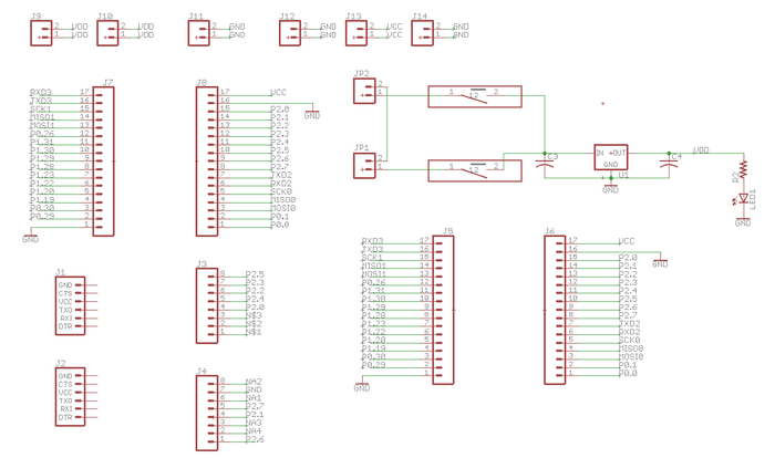
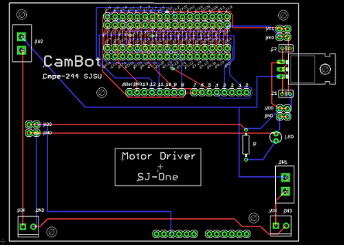
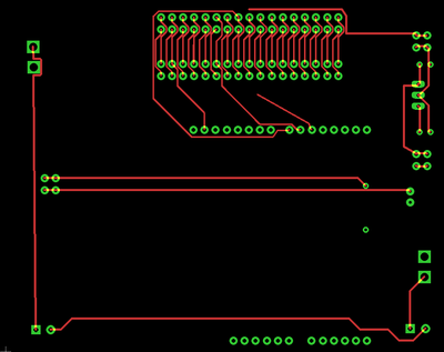
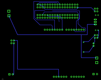
Eagle 8.1.0 software is used for PCB design.We created a 2 layer PCB of size 10cm x 8cm.
The steps involved in the PCB design process are discussed below.
1. PCB Schematic Design:
In the first step, we need to design a circuit using components available in Eagle library.Here two important things to keep in mind are:
- The Electrical Characteristics: Based on our requirement of voltage or current rating, we select the components which are suitable for our board.For example, if we want to connect a switch to conduct 5A current, we should not select a switch with 2A current rating from the library because the copper width for 2A switch will not be able to conduct 5A current.
- Components Selection: We need to carefully select the components here because each component has specific dimension as defined in their library.So once we convert this schematic into board layout, the size of the pads printed on the board depends on the component selection.We can't change the size if we select the library components.But there is a way we create our custom components with required electrical characteristics and dimensions.For our design, we used most of the parts from the Sparkfun library as it is very reliable and some of the parts which are not available in the library are created manually using Eagle.
EAGLE Components Used:
| Parts# | Part Name | DEVICE | LIBRARY | PACKAGE | Quantity |
|---|---|---|---|---|---|
| 1 | LED | LED3MM | SparkFun | LED_3MM | 1 |
| 2 | Toggle Switch | TOGGLE_SWITCH | toggle_switch(Custom library) | TOGGLE_SWITCH(Custom Package) | 2 |
| 3 | Famale Connectors | CONN_08" | SparkFun-Connectors | 1X08 | 2 |
| 4 | Female Connectors | 6_PIN_SERIAL_TARGET | SparkFun-Connectors | 1X06 | 2 |
| 5 | Male Connectors | CONN_17 | SparkFun-Connectors | 1X17 | 4 |
| 6 | Male Connectors | CONN_02 | SparkFun-Connectors | 1X02 | 6 |
| 7 | Terminal headers | M023.5MM | SparkFun | SCREWTERMINAL-3.5MM-2 | 2 |
| 8 | Capacitors | C-US025-025X050 | rcl | C025-025X050 | 2 |
| 9 | Resistors | R-US_0207/10 | rcl | 0207/10 | 1 |
| 10 | Voltage Regulator | V_REG_78XX-TO-220 | SparkFun-IC-Power | TO-220-ALT | 1 |
2. PCB Board Layout:
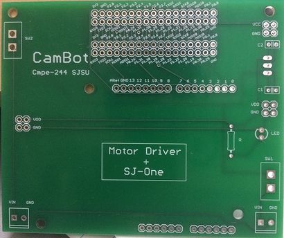
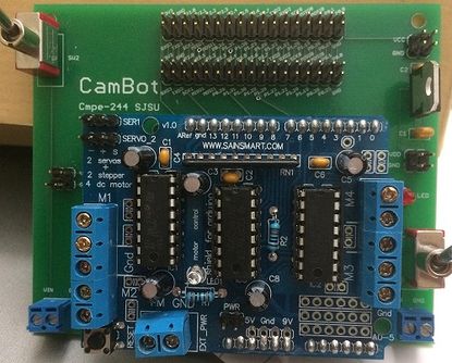
PCB board layout involves mainly placing components in the layout and routing them together.we can do manual routing or auto routing to connect components together with copper lines.But sometimes auto routing does not work or it will not be able to route all the connectors in an efficient manner.So manual routing is the best way where we will be able to plan and do the routing. In our project, the main challenges faced while PCB design is placing connectors and components in the appropriate place.Since we used a motor driver shield, which has 14 pin male connectors on the one side and 12 pin male connectors on the other side, it was very important that we measure proper dimension to fit this board on female connectors placed on PCB.We used dimension tool of the eagle to fix the accurate placement of connectors. The other challenge involved in the PCB design is routing the 34 pin connector for connecting SJ-one board to PCB.We decided to leave out extra 34 pin connector corresponding to SJ-one board because it can be used for any additional features added to our project.
In this process, we used Eagles add-on features to check for any error in our design.It is important that we follow all the strict PCB design guidelines before generating Gerber files for PCB manufacturing.
The features of PCB:
- Power supply circuit with 12V,5V and 3.3V connectors.
- Switch to control power to SJ-One board and Switch to control power to Motor driver shield.
- Female connectors to place Adafruit Motor Driver shield.
- 34 pin male connectors to connect SJ-one board to PCB.
- Extra 34 pin male connectors covering all 34 pins of SJ-one board for future use or if any extra features added.
Overall PCB design was a great learning experience and we would like to offer following tips to readers who are new to PCB:
1. Follow Sparkfun Eagle tutorial or a similar one to learn the guidelines and rules for PCB design.
2. Try to select components from standard libraries like Sparkfun to make sure that we get the proper components according to the PCB specification.
3. It is better to select Through Hole components because it is easy to solder and is easily available in the market.
4. Give careful attention to components ratings and size because it will determine pads size for this components.
5. Carefully select the thickness of copper wire for routing.Because for high current lines like supply line we need thicker one and for GPIO's and all we need thinner one.
6. Use the dimension tool properly to place the components in the desired place.
7. Also if it is a two layer PCB, please make sure that there are fewer copper wires passing near component pads in back layer.It will make the soldering process easy without any damage to PCB.
8. Before giving PCB to manufacturing please check with the guidelines provided by vendors to make sure we meet all the PCB design rules.
Hardware Interface
The hardware components used in this project include:
- Motor Shield
- Stepper Motor
- DC Motor
- Bluetooth module.
Motor Shield
The Adafruit motor shield is used in this project.
Why use a motor shield?
- Stepper motor requires huge current. The micro-controller does not cater to this requirement. Motor shield IC is capable of handling such high currents.
- Since the stator coils behave as an inductor, a change in the direction of current results in huge spikes. This can damage the microcontroller. The H bridge can proetct the microcontroller in such a case.
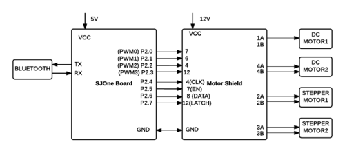
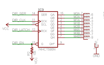
The Adafruit motor shield comprises of two L293D dual H-bridge motor driver ICs. It has four digital inputs which are in pairs. Each pair controls a motor. The motor shield has a shift register which facilitates the host controller to send data in serial manner which saves some of the pins of controller. The operation can be explained with an example. If pin 7 is set low and pin 2 is set high, motor 1 is turned on. Reversing the inputs will reverse the motor.
In order to conserve pins, the motor driver IC pins are wired to the outputs of 74HCT595N IC which is an 8-bit shift register. The data is fed in serially into this IC which then outputs the data in the parallel form.
The inputs to the shift register consisting of:
- DIR_EN: Enable Input (Active Low)
- DIR_SER: Data Input
- DIR_CLK: Rising edge results in shifting in of the input data bit
- DIR_LATCH: Rising edge results in internal bits to be moved out as parallel data
Motor Shield and SJOne Interface
| Motor Shield Pin | SJOne Pin |
|---|---|
| 4 (CLK) | P2.4 |
| 7 (EN) | P2.5 |
| 8 (DATA) | P2.6 |
| 12 (LATCH) | P2.7 |
Stepper Motor
Stepper motor is used to obtain the rotation of the phone for capturing a time-lapse.
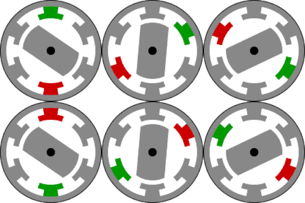
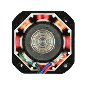
Stepper motors consist of a rotor and stationary electromagnets around the rotor. The movement of the rotor is controlled by energizing the electromagnets in a particular sequence as required. The movement of the rotor occurs as the rotor is attracted towards the electromagnets.
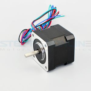
In this project, we use the NEMA 17 stepper motor which has a precision of 200 steps per revolution. Based on the angle required, the stepper motor can be configured to take the required number of steps in the provided direction.
NEMA 17 is a bipolar stepper motor. In the case of bipolar stepper motor, in order to reverse the polarity of stator poles, the current needs to be reversed. It is a 2-phase stepper motor and has one winding per phase. It has four leads. Each pair of leads is connected to one winding.
Method to test the leads
Each pair corresponds to one winding.
- If the resistance measured between one pair is infinite, the two wires in the pair belong to different windings.
- If the resistance measured between one pair is a definite value, the two wires in the pair belong to the same winding.
Each pair of these leads is connected to the motor input pins of the Motor Shield.
Stepper Motor and Motor Shield Interface
| Stepper Motor | Motor Shield |
|---|---|
| 2A and 2B | M2 |
| 3A and 3B | M3 |
SJOne PWM for Stepper Motor
| Stepper Motor | SJOne Pins |
|---|---|
| 2A and 2B | P2.0 (PWM1) |
| 3A and 3B | P2.3 (PWM4) |
DC Motor
DC motor is used in this project to move the robot forward and backward. Two DC motors are used each connected to a wheel.
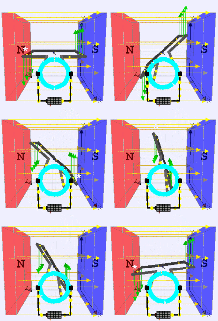
The DC motor converts electrical energy to mechanical energy. It consists of a current carrying conductor placed in an electromagnetic field. When current is passed through the conductor, a mechanical force is generated due to the electromagnetic effect.
DC Motor and Motor Shield Interface
| DC Motor | Motor Shield |
|---|---|
| DC Motor 1 | M1 |
| DC Motor 2 | M4 |
SJOne PWM for DC Motor
| DC Motor | SJOne Pins |
|---|---|
| DC Motor 1 | P2.1 (PWM2) |
| DC Motor 2 | P2.2 (PWM3) |
Bluetooth Module
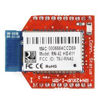
RN42XV is built around Microchip's RN42 low power Bluetooth module. Some features of this module are as follows
- Based on the popular 2 x 10 (2mm) socket footprint.
- Voltage range: (3-3.6)Volts
- Current range: 26 μA sleep, 3 mA connected, 30 mA transmit.
- UART data connection interface.
- Sustained data rates: 240 Kbps (slave), 300 Kbps (master)
- Transmission range up to 60 feet (20 m) distance, +4 dBm output transmitter, -80 dBm typical receive sensitivity.
- FHSS/GFSK modulation, 79 channels at 1-MHz intervals.
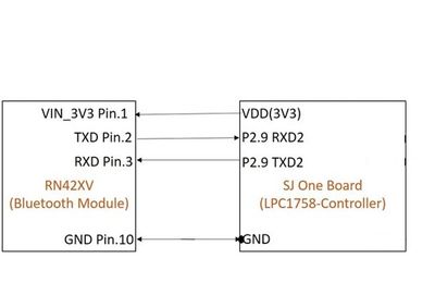
The Bluetooth module uses simple UART communication protocol for sending/receiving data from the Micro-controller board. we are using UART2 to communicate with the Bluetooth module.
Software Design
The software design consists of 3 tasks:
- Bluetooth Task
- Stepper Motor Task
- DC Motor Task
The Bluetooth task is of high priority since the user data needs to be received and acted upon. The Stepper Motor and the DC Motor tasks are run with medium priority.
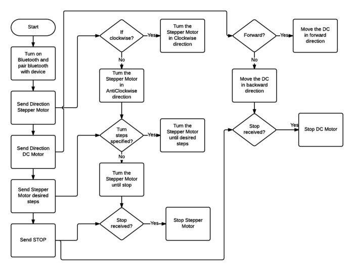
Algorithm
- In the idle state, the DC Motor and Stepper Motor tasks wait for command from the bluetooth application.
- Application commands are received using the Bluetooth task which performs UART data send and receive functionalities.
- The application sends:
- Direction for movement (forward or backward) to the DC Motor.
- Direction for rotation (clockwise or anticlockwise) and angle of rotation to the Stepper Motor.
- Based on the data received, the motors are configured.
- DC Motor: PWM is provided from the SJOne board which is routed to the DC motor through the Motor Shield.
- Stepper Motor: Specific bits are latched into the Motor Shield in order to energize the coil in the required sequence.
- PWM for stepper motor is configured using SJOne board. The rotation is configured as step angles based on the angle provided.
- The Start and Stop commands from the application are used to trigger or stop the motors.
Flowchart
Implementation
The software implementation can be divided across the modules:
- Motor Shield Implementation
- Stepper Motor Implementation
- DC Motor Implementation
- UART interface
- Android Application Development
Motor Shield Software Implementation
The shift register in the motor shield requires 4 inputs. They are configured using SJOne GPIOs as below:
GPIO MOTORLATCH(P2_7);
GPIO MOTORDATA(P2_6);
GPIO MOTORCLK(P2_4);
GPIO MOTORENABLE(P2_5);

MOTORLATCH.setAsOutput();
MOTORENABLE.setAsOutput();
MOTORDATA.setAsOutput();
MOTORCLK.setAsOutput();
Latch enabling is required every time a data is set since it controls the data moving into the shift register and the parallel data being sent out of the motor shield. This functionality of latching motor state data is implemented as follows:
for(i=0; i<8; i++)
{
     setMotorClockLow();

     if(latch_state & (1 << (7-i))
     {
           setMotorDataHigh();
     }
     else
     {
           setMotorDataLow();
     }
     setMotorClkHigh();
}
setMotorLatchHigh();
Stepper Motor Task Implementation
PWM Initialization:
PWMs 1 and 4 are used for Stepper Motor.
GPIO PWM1(P2_0);
GPIO PWM4(P2_3);

PWM1.setAsOutput();
PWM4.setAsOutput();
Latching
Latching is required since the input is taken serially by the Motor Shield and rendered as parallel output. This design aims at reducing the number of pins.
In order to enable the stepper motor, the coils need to be energized in a particular sequence based on requirement. Energizing each of the coils is controlled by using a bit to represent the state of each coil. This bit is latched into the latch_state variable. This data is used to enable the energizing of the required coil.
The Stepper motor coils are energized in the following sequence based on the command received from the application:
Latching for clockwise direction:
latch_state |= (1 << MOTOR3_A) | (1 << MOTOR2_A);
latch_state |= (1 << MOTOR2_A) | (1 << MOTOR3_B);
latch_state |= (1 << MOTOR3_B) | (1 << MOTOR2_B);
latch_state |= (1 << MOTOR2_B) | (1 << MOTOR3_A);
This sequence results in clockwise rotation.
Latching for anti-clockwise direction:
latch_state |= (1 << MOTOR2_B) | (1 << MOTOR3_A);
latch_state |= (1 << MOTOR3_B) | (1 << MOTOR2_B);
latch_state |= (1 << MOTOR2_A) | (1 << MOTOR3_B);
latch_state |= (1 << MOTOR3_A) | (1 << MOTOR2_A);
This sequence results in anti-clockwise rotation.
DC Motor Task Implementation
PWM Initialization:
PWMs 2 and 3 are used for DC Motor.
GPIO PWM2(P2_1);
GPIO PWM3(P2_2);

PWM2.setAsOutput();
PWM3.setAsOutput();
The DC motor is activated based on the command received from the application:
Latching for forward direction:
latch_state |= (1 << MOTOR1_A);
latch_state &= ~(1 << MOTOR1_B);

latch_state |= (1 << MOTOR4_A);
latch_state &= ~(1 << MOTOR4_B);
This sequence results in a forward motion.
latch_state |= (1 << MOTOR1_B);
latch_state &= ~(1 << MOTOR1_A);

latch_state |= (1 << MOTOR4_B);
latch_state &= ~(1 << MOTOR4_A);
This sequence results in a backward motion.
Control of Stepper and DC Motor
Stepper Motor steps can be controlled based on input from Android Application. To rotate the stepper motor, it has to go through phase 1 to 4 to energize the 4 coils in particular sequence based on desired angle and direction. Similarly, DC motor movement is controlled in forward or backward direction.
Structure has all the necessary control variables as below
   uint8_t direction;
   uint8_t fwd_reverse;
   uint8_t start_stop;
   uint8_t steps_degree;
Based on the values sent from application,
- 'direction' is set to clockwise/anticlockwise for Stepper Motor
- 'fwd_rev' to control the direction for DC Motor
- 'steps_degree' to control the desired amount of rotation that needs to be achieved by the Stepper Motor.
Bluetooth Task Implementation
The bluetooth task initializes UART2 for the communication with Zigbee Bluetooth module with the baud rate of 115200. It waits for a byte from UART2 in its run() function (which is always run in a loop as long as the task is running). The byte it receives can be decoded from the enumeration datatype declared to represent the commands from the app. Below is the definition of the Bluetooth task used along with the enum datatype.
class bluetooth_task : public scheduler_task
{
private:
	Uart2 &Bluetooth_uart_2;
	static const int Rx_Q_Size = 3;
	static const int Tx_Q_Size = 3;
	static const int Baud_Rate_Bluetooth_Uart2 = 115200;
	char buff;
public:
	bluetooth_task(uint8_t priority) :
		scheduler_task("Bluetooth Task", 2000, priority),Bluetooth_uart_2(Uart2::getInstance())
        {
		Bluetooth_uart_2.init(Baud_Rate_Bluetooth_Uart2,Rx_Q_Size,Tx_Q_Size);
		buff = 0;
        }

	bool init(void);
	bool run(void *p);
};

enum command
{
   init,
   start,
   stop,
   clockwise,
   anticlockwise,
   angle30,
   angle60,
   angle90,
   angle120,
   angle150,
   angle180,
   forward,
   backward,

};
Android App Implementation
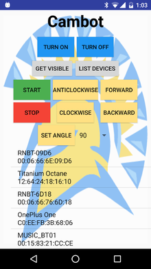
The android application to control our CamBot is a simple one screen application. The screenshot showing the button layout (UI) is given on the right. The table with the button descriptions is given below. Any button press will result in sending of the command byte via Bluetooth to board module which will be received via UART. The Bluetooth task and android app communication will receive all and any message sent. The motor task will decide what to do with the received commands and whether it is valid or not, with respect to the software flow.
Steps involved in the Android Application
- The android code starts at MainActivity.java where an UUID is initialized for the Bluetooth adapter objects created in the MainActivity class.
- After this, a Bluetooth socket is created using the above mentioned UUID.
- A list is created which is initialized with the paired devices of the Application host.
- Clicking on any of these would start a connection with the device ID via the socket object.
- After connection is established, any command sent would be done so via this created socket object.
- The next function call would be based on what button is pressed.
- There are onClickListeners for all these buttons which would send the respective commands on button press.
An important point to note here is that the app uses the MAC address (like 00:06:66:6E:09:D6 for the device RNBT-09D6) to connect. Hence before connection thread is started, you need to give the device MAC address to the Bluetooth socket. You can either hardcode the address in the program, or as we have implemented, use an OnClickListener to check which device was selected through touch, retrieve its respective MAC address from the created list and then give it to the Bluetooth socket.
The android UI can be designed in two ways. One is purely through GUI, where you can drag and drop the required items like a button or text field. Another way is through text where you manually type in the parameters for the UI object. The way these objects are placed are described through their layout. You can choose between two kinds of layouts: Constraint Layout and Relative Layout. A relative layout is where you define the position of the UI objects with respect to the screen edges. A constraint layout is similar to a relative layout but with the additional availability of a bias where you can position it by adding more rules by adding constraints like the distance between two buttons etc. We have used Relative Layout to design the UI of our app.
| Button | Functionality |
|---|---|
| TURN ON | Turn on the Bluetooth on the mobile |
| TURN OFF | Turn off the Bluetooth on the mobile |
| GET VISIBLE | Makes your mobile device visible to other Bluetooth devices |
| LIST DEVICES | Lists all the Bluetooth devices paired with the mobile. You can click on any of the listed devices to connect to it |
| START | After giving appropriate commands and parameters, pressing this button will set the cambot in motion |
| STOP | This stops the motion of the CamBot |
| ANTICLOCKWISE | Press this button to set the direction of rotation of the camera holder stepper motor to anticlockwise direction |
| CLOCKWISE | Press this button to set the direction of rotation of the camera holder stepper motor to clockwise direction |
| FORWARD | Press this button to set the direction of movement of the dc motor to forward direction |
| BACKWARD | Press this button to set the direction of movement of the dc motor to backward direction |
| SET ANGLE | First select appropriate angle for the above discussed stepper motor using the list to the left of this button. Then press this button to set the angle of rotation of the stepper motor |
Testing & Technical Challenges
Technical Challenges
Issue 1: Connecting Android Application with Zigbee module
We had a problem connecting the android app with Zigbee module via Bluetooth. The app was initialising connection but was not able to finish the connection process and get connected.
Solution: The RFComm socket was not getting created properly. Even when the RFComm socket was created, it was not created with the accurate device UUID that needed to be setup. After manually setting up the device UUID and then creating the RFComm socket, we could start the Bluetooth connection with that socket object and then it would successfully connect with the Bluetooth module.
Issue #2
We faced an issue while placing the camera mount on the stepper motor. A coupler was used to connect the stepper motor shaft and the camera mount. We tried many couplers but there always existed a small mismatch on either at the camera mount end or the stepper motor shaft end. This resulted in amplification of even a small vibration during stepper motor rotation resulting in severe vibration of the camera mount when the stepper motor was activated. The mount also consisted of several moving parts which added to the issue. This was a critical issue as camera needs stable platform to capture the time-lapse.
Solution: We bought couplers suiting the motor shaft diameter and then tried several screw sizes and washers to obtain a stable mount. We adjusted the coupler placement on the motor shaft for minimal shakiness. Also, we replaced the initial mount which had several moving parts with a mount which a single solid piece.
Issue #3
We faced problem in choosing a small SPST toggle switch in Eagle library during PCB schematic design as the required specification and dimension was not available in the library.
Solution: We decided and developed our own customized switch using Eagle with the required dimension and specification that fit our board perfectly.
Testing
Bluetooth Module - Android App
We tested the effective communication between the android app on smartphone and the SJOne Board with Zigbee Bluetooth module by just running the Bluetooth task on SJOne board which waits for data from Bluetooth module and prints the data whenever it receives it. With this, we were able to do regression testing of all button presses without any regard to the functional flow for the order of button press. All button presses generated and sent the command data to the board and was successfully printed.
Stepper motor Control using App
The stepper motor was tested first by manually sending signals from SJOne board. Then we switched over to control it using the android app by removing all other modules and checking if the angle and direction that was given by the app was received by the board and decoded (by printing the received command on the terminal). Then we saw the direction of rotation of the mount on the stepper motor and the angle it rotates till and checked if it is roughly the same as the command given by the app.
DC Motor control using App
This testing procedure is similar to the testing of the stepper motor where we first tested by manual signalling from the board and then proceeded to test using control from the android app.
Overall Testing
We tested the final assembled CamBot by connecting the board with Android app and sending commands for Stepper motor and DC motor and then pressing Start. The CamBot proceeds to move as commanded and comes to halt when the Stop command is given from the app. We also checked the stability of the mount and vibrations encountered during motion and made some mechanical adjustments to reduce the vibrations.
Conclusion
The CamBot project taught us several aspects, both in terms of technical knowledge and project management. We went through design, development and testing phases. We gained knowledge regarding the hardware interfaces and FreeRTOS programming. Working on the motor interfaces, we had to reverse engineer the motor shield connections due to the lack of datasheets. We worked on Android application and bluetooth interface. We had the opportunity to learn the application and driver interface. An important learning from this project was the difficulty involved in hardware assembly. The project involved mounting the camera on the stepper motor. We realized how a minor vibration at the coupler used to connect the stepper motor and the camera mount could amplify at the camera mount. It would not be an exaggeration to say that we did spend a considerable amount of time fixing this. The suggestion that we would like to provide to all teams planning on projects that involve a lot of hardware assembly is to start early and test tremendously. We had fun designing the PCB for our project. It was new to us and we enjoyed the extensive learning that the process imparted. CamBot made us understand how to work in a team and our mistakes taught us an important lesson of time management. Overall, it was a great learning experience.
Project Video
CamBot Demo Video: https://www.youtube.com/watch?v=r5eV1bO_z0Y
CamBot Captured Video: https://www.youtube.com/watch?v=Ctgkzu7IBR8
Project Source Code
https://gitlab.com/aajna.karki/cmpe244_CamBot
References
Acknowledgement
We would like to thank Professor Preetpal Kang for providing a great platform to learn Real-Time Operating Systems. The well-modularized course enabled us to understand and implement the concepts of FreeRTOS. We learnt significantly while working on our project. We would like to express our gratitude for his continued guidance throughout the semester. Also, we appreciate the Student Assistants of this course for their immense support and the knowledge shared.
References Used
[1] Preetpal Kang's lecture notes of CMPE 244, Computer Engineering, San Jose State University, Feb-May 2017
[2] https://docs.google.com/document/d/1OdGS0QHKCdbrbAs_x62gmfSx_UdUPFPgZjwZnVDVHDg/preview
[3] https://developer.android.com/training/basics/firstapp/building-ui.html
[4] https://www.tutorialspoint.com/android/android_bluetooth.htm
[5] https://learn.sparkfun.com/tutorials/tags/eagle
