S17: Smart Planter
Contents
- 1 Smart Planter
- 2 Abstract
- 3 Objectives & Introduction
- 4 Schedule
- 5 Parts List & Cost
- 6 Design & Implementation
- 7 Rain sensor
- 8 Temperature/Humidity sensor
- 9 Soil Moisture Sensor
- 10 Light Sensor
- 11 LCD
- 12 Soil Moisture Sensor
- 13 Temperature/Humidity sensor
- 14 Testing & Technical Challenges
- 15 Conclusion
- 16 References
Smart Planter
Abstract
This project aims at developing an automatic irrigation and lighting system for plants. An Android app allows a user to remotely monitor and manually control the watering and lighting for the plant.
Objectives & Introduction
The SJOne board sends sensor readings to an Android app through a server. The Android app can also send commands to the SJOne board through the server (such as turning the water pump on or off).
An Android Things app runs on a Raspberry Pi 3 to provide Internet connectivity to the SJOne board and to get timestamps of when the plant was last watered (future enhancements can include more useful features with APIs from Google). The two boards communicate over UART.
Team Members & Responsibilities
- Sona Bhasin
- Temperature/Humidity sensor
- Rain sensor
- Code integration and testing
- Johnny Nigh
- Android app
- Server application
- Android Things app
- Communication between the SJOne and Android Things app
- Thrishna Palissery
- Soil moisture sensor
- Light sensor
- LCD
- Code Integration and testing
- Hugo Quiroz
Schedule
| Week # | Start Date | End Date | Task | Status | Actual Completion Date |
|---|---|---|---|---|---|
| 1 | 03/14/2017 | 03/21/2017 |
|
Completed | 03/23/2017 |
| 2 | 03/24/2017 | 04/04/2017 |
|
Completed | 04/06/2017 |
| 3 | 04/04/2017 | 04/14/2017 |
|
Completed | 04/15/2017 |
| 4 | 04/04/2017 | 04/11/2017 |
|
Completed | 04/10/2017 |
| 5 | 04/11/2017 | 04/28/2017 |
|
Completed | 04/22/2017 |
| 6 | 04/11/2017 | 04/25/2017 |
|
Completed | 04/25/2017 |
| 7 | 04/11/2017 | 04/28/2017 |
|
Completed | 05/05/2017 |
| 8 | 04/18/2017 | 04/30/2017 |
|
Completed | 04/30/2017 |
| 9 | 04/20/2017 | 05/05/2017 |
|
Completed | 04/28/2017 |
| 10 | 05/06/2017 | 05/10/2017 |
|
Completed | 05/12/2017 |
| 11 | 05/10/2017 | 05/15/2017 |
|
Completed | 5/19/2017 |
| 12 | 05/11/2017 | 05/21/2017 |
|
Completed | 5/25/2017 |
Parts List & Cost
| Item # | Description | Distributor | Qty | Cost |
|---|---|---|---|---|
| 1 | SJOne Board | 1 | $80.00 | |
| 2 | Soil Moisture sensor | Amazon | 1 | $5.99 |
| 3 | Light sensor | Amazon | 1 | $8.99 |
| 4 | Rain sensor | ebay | 1 | $1.99 |
| 5 | Temperature and Humidity sensor | Amazon | 1 | $7.99/4 pieces |
| 6 | DC water pump | Amazon | 1 | $12.99 |
| 7 | Flow meter | Amazon | 1 | $10.99 |
| 8 | Raspberry Pi 3 | Amazon | 1 | $36.78 |
| 9 | Voltage regulator (3.3V) | Sparkfun Amazon | 1 | $1.95 |
| 10 | Voltage regulator (5V) | Amazon | 1 | $7.99/12 pieces |
| 11 | LCD display (20x4) | Amazon | 1 | $32.10 |
| 12 | Lamp | 1 | ||
| Total: $207.76 |
Design & Implementation
Hardware Design
Discuss your hardware design here. Show detailed schematics, and the interface here.
Hardware Interface
Rain sensor
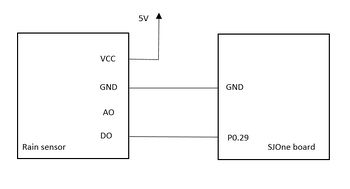
The rain sensor is used in the project to detect if it is raining. This helps the Smart Planter to decide if it needs to water the plants if the moisture level falls below desired value. The sensor requires 5 V power supply. The digital output of the pin is connected to P0.29 of SJOne board. When rain drops fall on the conductive plate connected to rain sensor, the conductive plate elements are bridged by the rain water and the digital pin output goes low. To read the rain sensor, we have implemented GPIO external interrupt to be triggered on detecting falling edge.
Temperature/Humidity sensor
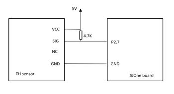
The temperature/humidity sensor being used in the project is AOSONG DHT11 that uses single-wire protocol for communication. The sensor requires 5V power supply. The output signal of the sensor is connected to P2.7 of SJOne board and to 5V VCC with a pull-up resistor of 4.7kΩ. The sensor keeps track of the temperature and humidity for the Smart Planter system. The ideal temperature range for plants is between 50 °F and 80 °F while the humidity range is between 40% and 60%. If the temperature falls below 54°F, the user is intimated using the Android app. The pin diagram for interfacing the temperature/humidity sensor with SJOne board is shown below.
The sensor waits for the microcontroller to pull the line low for a period of 18 ms on its signal pin. The sensor then briefly pulls the line high as “wait time” and then sends an acknowledgment signal which comprises of 80 µs of low time and 80 µs of high time. Subsequently, the sensor sends 40 bits of humidity, temperature and checksum data respectively. The bits are differentiated as 0 or 1 based on the duration for which the signal remain high. The bit 0 is represented by a signal which goes low for 50 µs followed by high time of 28-30 µs while the bit 1 is represented by a signal which goes low for 50 µs and then high for 60-70 µs. The sensor needs 1 s between reads to provide correct data. The data provided by sensor is of the form: 8-bit integer humidity data + 8-bit decimal humidity data + 8-bit integer temperature data + 8-bit decimal temperature data + 8-bit checksum.
Soil Moisture Sensor
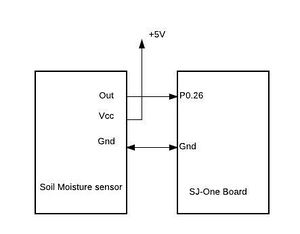
This soil moisture sensor can read the amount of moisture present in the soil surrounding it. It uses the two probes to pass current through the soil, and then it reads that resistance to get the moisture level. More water makes the soil conduct electricity more easily (less resistance), while dry soil conducts electricity poorly (more resistance). It outputs an Analog signal. It is a simple, 5-volt dc collector, emitter follower output monitoring the soil resistance as a base drive of the emitter follower. The more moisture the lower the base resistance and the more base current. Therefore, the more moisture the greater the emitter follower output voltage 0 to approx. 3.3 volts max. This output pin is connected to P0.26 pin of SJ-One board. The pin is configured as an ADC pin. The analog output from the soil moisture sensor is converted to digital signal via ADC of SJ-One board. If the moisture content is below a threshold a DC pump is turned on which waters the plant.
Light Sensor
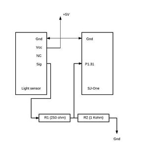
The light sensor is used to detect the current ambient light. The light sensor which is used in this project uses a photo resistor. It changes its resistance based on the amount of light that falls upon it. The light sensor produces an analog output voltage in the range of 0-4v max. This analog output is connected to the pin P1.31 of SJ-One board which is configured as ADC. Since the SJ-One pins can tolerate only a max of 3.3v, the output from the light sensor is stepped down to 3.3 v using a voltage divider. The stepped down voltage is then given as the input to the ADC pin. The light sensor requires 5V supply voltage. If the amount of light falls below a threshold a lamp is turned on.
LCD
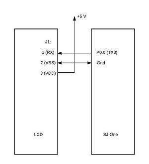
The Liquid Crystal Display used for this project was NHD-0420D3Z-NSW-BBW-V3. This display uses a built-in PIC16F690 for serial communication. It can work in different modes (I2C, SPI, RS232/UART). RS232/UART was used for this project as communication. To enter the RS-232 mode, both R1 and R2 on LCD should be open. A 5v voltage supply is provided. The pin P0.0 of SJ-One board is used as the TX 3 (UART3) pin. This pin is connected to the RX pin of LCD display. The baud rate used for communication was 9600. The communication format is 1 Start bit, 8-bit data, 1 Stop bit, no parity, no hand-shaking.
Software Design
Show your software design. For example, if you are designing an MP3 Player, show the tasks that you are using, and what they are doing at a high level. Do not show the details of the code. For example, do not show exact code, but you may show psuedocode and fragments of code. Keep in mind that you are showing DESIGN of your software, not the inner workings of it.
Soil Moisture Sensor
The following task are used by the soil moisture sensor.
scheduler_add_task(new moisture_sensor_task(PRIORITY_LOW));
xTaskCreate(test_task, (const char* )"test", STACK_BYTES(2048), 0,PRIORITY_MEDIUM, 0);
Implementation
This section includes implementation, but again, not the details, just the high level. For example, you can list the steps it takes to communicate over a sensor, or the steps needed to write a page of memory onto SPI Flash. You can include sub-sections for each of your component implementation.
Temperature/Humidity sensor
To implement the single-wire protocol, we have made use of a timer interrupt and GPIO external interrupt. The timer interrupt has been configured to be triggered every 30 µs and the GPIO external interrupt has been configured to be triggered when a rising edge is detected on the pin. We have also made use of semaphore and tasks to effectively achieve the purpose.
The sequence of steps to read the temperature/humidity sensor is as follows:
- The GPIO pin P2.7 is set as an output pin.
- The microcontroller sets the pin low for 18 ms.
- The pin P2.7 is set as input pin.
- The external interrupt at rising edge is enabled on P2.7.
- The sensor then pulls the signal high briefly as wait time followed by an acknowledgment signal and 40 bits of data.
- On detecting rising edge, the timer interrupt is enabled in the callback function for external interrupt on pin P2.7.
- Within the timer interrupt ISR, if the signal is still high after the 30 µs, it in interpreted as bit 1 and if the signal falls low after 30 µs, then it is interpreted as bit 0. The values are stored in an array. Once all 40 bits of data has been received, a function to convert the values stored in array to decimal equivalent is called, which provides the humidity data in % and temperature data in °C, converted to °F.
Testing & Technical Challenges
Describe the challenges of your project. What advise would you give yourself or someone else if your project can be started from scratch again? Make a smooth transition to testing section and described what it took to test your project.
Include sub-sections that list out a problem and solution, such as:
My Issue #1
Discuss the issue and resolution.
Conclusion
Conclude your project here. You can recap your testing and problems. You should address the "so what" part here to indicate what you ultimately learnt from this project. How has this project increased your knowledge?
Project Video
Project Source Code
References
Acknowledgement
Johnny Nigh would like to thank Michael Nigh for his help with setting up the server and help with the basics on the Socket.IO JavaScript library.
References Used
- Android Things - Getting Started with the SDK Preview
- Android Things - Samples - UART Loopback
- Hoisington, Corinne. Android Boot Camp for Developers Using Java: A Guide to Creating Your First Android Apps. Boston, MA: Cengage Learning, 2016.
- Hardy, Brian; Marsicano, Kristin; Phillips, Bill; Steward, Chris. Android Programming: The Big Nerd Ranch Guide, Edition 2. Atlanta, GA: Big Nerd Ranch, LLC. 2015.
Appendix
Future enhancements:
- Automatically get the timezone based on the location of the board that is running the Android Things app (using the Google Maps Timezone API).
- Add push notifications.
- I.e. a soft watchdog in the SJOne application can tell the Android Things app to alert the user (if a possible failure has been detected).
- Add support to turn watering and lighting on or off through voice commands (using the Google Assistant SDK).
