S13: Smart Security
Contents
Grading Criteria
- How well is Software & Hardware Design described?
- How well can this report be used to reproduce this project?
- Code Quality
- Overall Report Quality:
- Software Block Diagrams
- Hardware Block Diagrams
- Schematic Quality
- Quality of technical challenges and solutions adopted.
Smart Security
Safety often tends to wary people in various part of the world. Whether or not an individual is living in a neighborhood with high or low crime rates, security have always been a main concern. With the rising crime rates, even in area known to be safe, security companies have been trying to attract customer with their innovative features, but not so attractive pricing. Often the price could range anywhere starting at $1,400 for installation and from $23 a month [1]. Our project is to provide a solution for people who want a home security system, but not have to pay the huge installation cost and monthly fees.
Abstract
Smart Security is a system targeted for home security that continuously monitors movement, when armed. This system will alert the user wirelessly when it detects motion via text message and flash LEDs on the spot to try and scare off the intruder. The whole process can be control using a web based GUI for arming and disarming the system.
Objectives & Introduction
The Smart Security project communicates with the user using wireless connection to alert them of any movement within the proximity of the sensor. A PIR motion sensor is, connected to a LPC1758 microcontroller board, used as a detector to register any movement. A Wifly module, also attached to the LPC, maintain wireless connection to send and receive commands. The user is able to communicate with the board using a web based GUI, designed with Bootstrap, to arm and disarm the system as he/she please. When armed and motion is detected, the board will send commands to alert user using text messages. To prevent spam, users will receive periodic text messages versus one per motion detected.
Our objectives for the project:
- Interface PIR Sensor with LPC1758 board and register readings
- Use Wifly to communicate between the board and server
- Send alerts in the form of email/text messages when movement is detected
- Setup alarm in the form of flashing LEDs
- Create an interactive user web interface that handles the control of the sensor
- Setup connection between the board and server
Team Members & Responsibilities
- Kevin Deng
- Interfacing PIR Motion Sensor with LPC1758 Microcontroller
- Design Web UI
- Project Report and Documentation
- Testing
- Nelson Wong
- Interface Wifly module with LPC1758
- Wireless communication
- Testing
Schedule
| Week | Planned Tasks | Actual Tasks |
|---|---|---|
| 1 |
|
|
| 2 |
|
|
| 3 |
|
|
| 4 |
|
|
| 5 |
|
|
Parts List & Cost
| Item | Type | Quantity | Cost | Link |
|---|---|---|---|---|
Design & Implementation
Our project designs are composed of hardware and software, intercommunicating with one another to fulfill the overall process. The main component revolves around the sensor receiving and sending signals depending on the situation to a host server to transfer that signal into a message to the user. Each of these processes does so in a chain scenario where one depends on the other to function.
Hardware Design
Hardware components used in this project:
- LPC1758 MicroController
- Wifly Module
- PIR Motion Sensor
- Battery Pack
LPC1758 MicroController
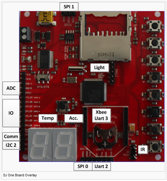
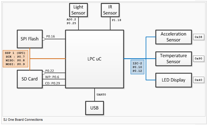
The LPC1758 is the center of control for our whole project. It connects everything together into a single system to perform necessary operation to make this project function. We have our Wifly module, PIR motion sensor, LEDs, etc. all connected to this LPC to communicate interchangeably. Without this component, this project will not function at all.
Wifly Module
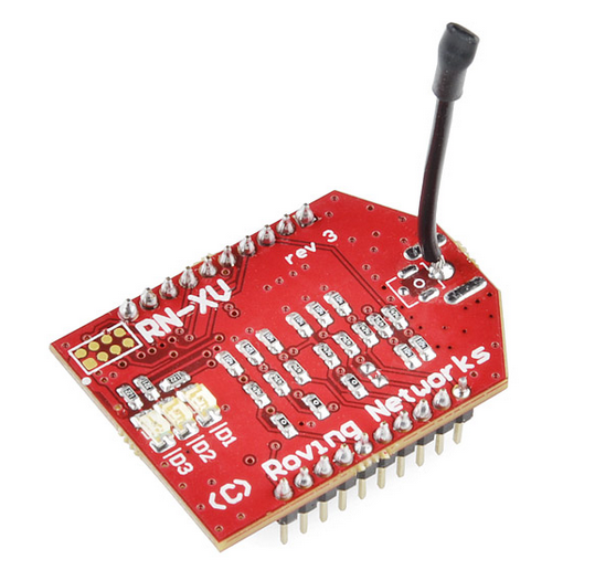
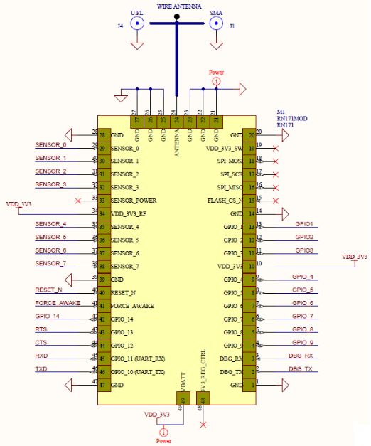
The RX-XV Wifly Module is our communication source between the wireless network and our overall system. The module is connected to our LPC1758 board and program to send and receive data based on events. This component allows us to communicate with the user and receive command from our website to arm and disarm the whole system. This device architecture is a standard TCP/IP platform and can migrate from 802.15.4 without any change.
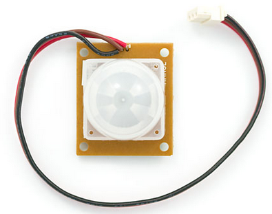
PIR Motion Sensor
The PIR motion sensor is our ‘eye’ for this project. Its main purpose is to detect motion within its proximity and log the result. The PIR is connected to our LPC1758 board and upon detection when armed, it will use the Wifly module to send an alert to the user. This component is very critical because it acts as our surveillance for our security system.
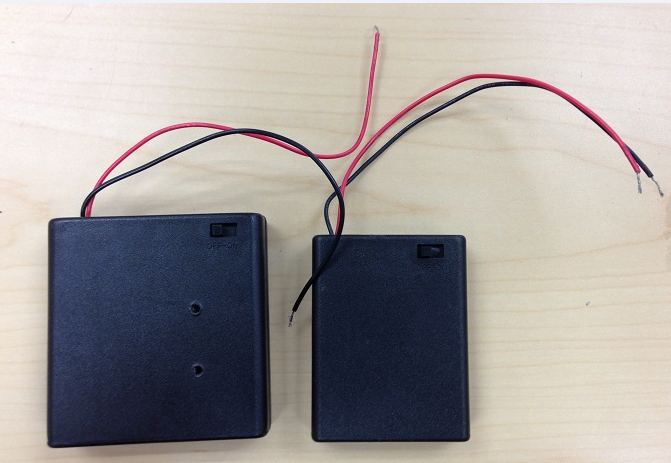
Battery Pack
Initially the board and the motion sensor pull-up were powered by two separate USB connections. We then interface it with a battery pack to supply the necessary voltage amount to both.
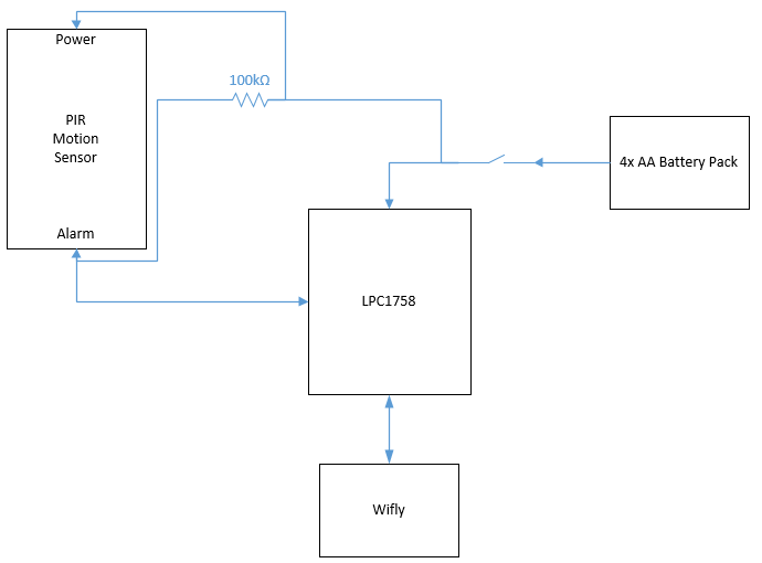
Top Level Connections
The following diagram shows the top level connection of all the components.
Hardware Interface
PIR Motion Sensor
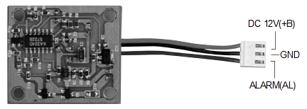
Our PIR motion sensor requires a pull-up resistor for the alarm pin. When the sensor is in idle state, not detecting anything, the alarm pin will be high, but once motion is detected, the pin will pull to a low. The reason behind it is, the alarm pin is an open collector. This type of setup allows multiple motion sensors to be connected at once.
Wifly Module
The Wifly module was design to be a direct replacement from XBee to wireless connection. Everything is a direct fitment on top of XBee UART3. Once the pins are connected, between the board and module, it will be slightly harder to take off and be careful of the surrounding pins, as it might push it outward a little.
Battery Pack
We connected our Battery pack to the 5V Power input on the development board. We just screwed in power and ground to their respective inlet.
Connection Table
Our connections between the LPC1758 development board and components can be seen on the table below:
| LPC1758 | PIR Motion Sensor | Wifly Module | Battery Pack |
|---|---|---|---|
Software Design
Communication Diagram
The project was built based off of lab knowledge and Preet’s Replay Controller Project for our wireless implementation. From our lab we use our knowledge of binary and mutex semaphores to handle tasks. Our sensor needs to handle communication from sensor to transmit and receive data. Whereas transmit and receive communicate with one another.
Motion Sensor
- Always supply reading when power is on
SJ-One Board
- Use Wifly module to connect to the wireless gateway
- Check for Commands
- Maintain count of the motion sensor if armed
- Disable count if disarmed
RN-XV Wifi Module
- Try to connect whenever possible and maintain connection
- Receive from wireless gateway
Webserver
- Handles request and transmission of commands
- Pass it to wireless gateway
Web UI
- Sends command to arm or disarm
Wireless Router/Gateway
- Handles connection between webserver to both mail server and mobile device
- Pass necessary commands
Mail Server
- Send email notification to user
Mobile Device
- Send text message to user's mobile device
Process Diagram
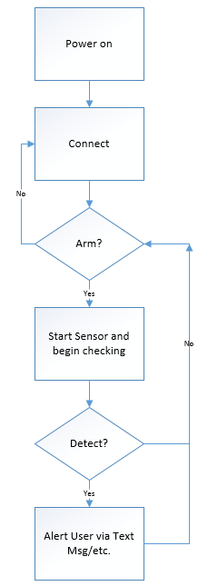
For our process diagram we made a simple layout of the operation once the board receives power. In the initial state we have to process the Wifly request to connect to the server. If connection is not stable we can not send the arm/disarm command. This step is very crucial to our whole process. Once the connection stage is stabilized, we will then began the check for the arm command. If it is not arm it will continue looping back to the previous stage and repeat. Once it is armed, the board will begin taking count on the sensor. Once detected it will increment the counter, and once it receives a certain amount it will send user a notification via text message and email. This process will repeat as long as the system is armed.
Implementation
Our implementation consist of several processes:
- Wifi Task
- Transmit
- Receive
- Sensor Task
- Web Interface
- PHP Script
- ARM
- DISARM
Wifi Transmit Task
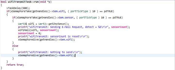
Our Wifi transmit task handles the process of sending out the counts recorded by the sensor. It will send it off to the web server under two circumstances:
1. Wifi Semaphore is true
2. Sensor Semaphore is true
The data will then be handle by the server and transmit to the user via email and text message.
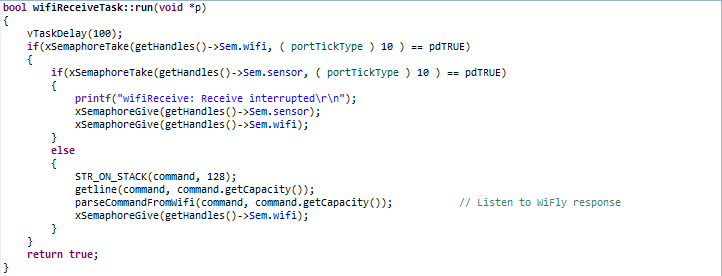
Wifi Receive Task
Similar to Wifi Transmit it follows the same two criteria in order for it run. It receives commands from the user to either arm or disarm the system. It has to make sure that during the receive, transmit is not operating so there won't be any collision.
Sensor Task
Sensor task handles a very crucial part of our project. It check if the system is armed by the user before it begins performing its operation. After validating that it is indeed armed, it will begin to monitor motion and if detected it will increment the sensor count. Once the sensor count reaches its threshold, hard coded by us, it will send a notification to the user. This is to prevent any spam of any sort from occurring.
Web Interface
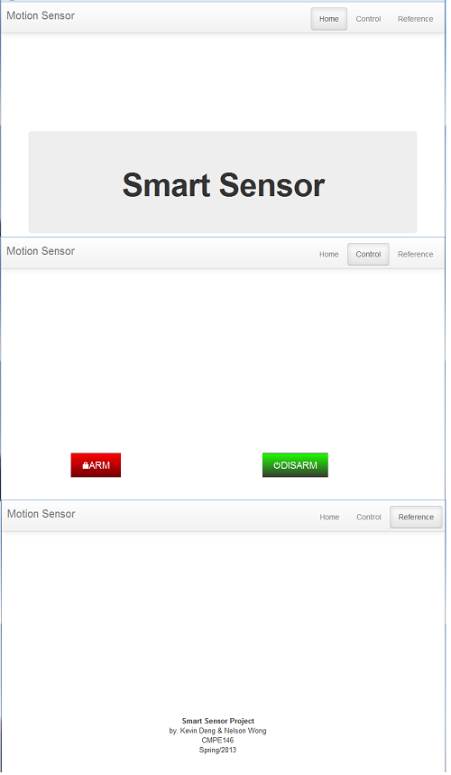
For our web interface we use Bootstrap from Twitter, to design our layout. Bootstrap is a perfect web development tool for beginner, in my perspective. It contains a lot of features, easy add-on, and a large array of references online to aid beginner like me to develop a simple user interface to interact with the user. We weren't able to fully develop our webpage, but it contains our main feature of arming and disarming our system. From there, we call our PHP script to handle the respective actions.
PHP Script
Our PHP scripts are composed of three different operations. The arm and disarm are associated with the buttons on the web interface and will handle the respective operation when a button is pressed. The third script is handling the notification portion of our system. It consists of the phone number and email address of the user. Once the sensor count reaches its threshold, it will call the transmit task to alert the user.
Final Product
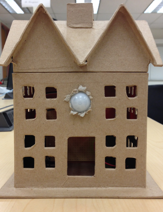
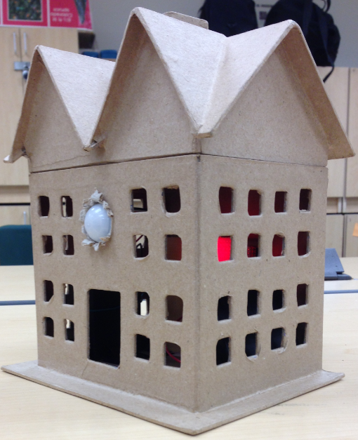
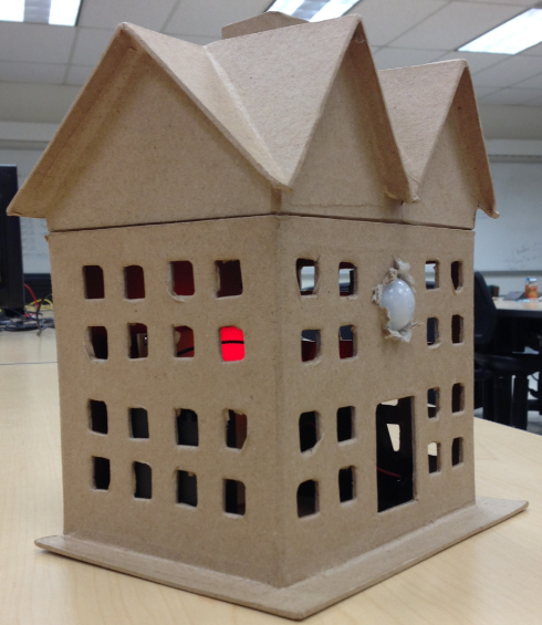
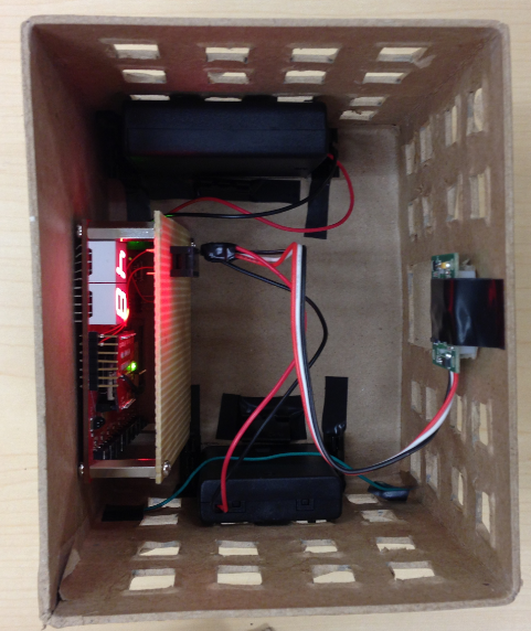
After we made sure everything is functioning we packaged it into a stealthy paper mache house that blends in with almost anything. It will be hard to notice for intruder, you can position it anywhere in your house like decorations and have great heat dissipation for the system during hot weather.
Testing & Technical Challenges
Testing were done on our system on a step by step bases. We followed our report schedule and test the job done that week before moving on to the next. On rare occasion, due to time constraint, we had to move on to the next task before fully debugging the previous. Since we had two people in our group, we were responsible for testing and debugging our respective parts. During our testing we recorded the challenges that took place and our solution to these problems.
Test Cases
Sensor Test Cases
- Setup a mock output whenever motion is detected
- Check various light setting and the response
Wifly Test Case
- TCP/IP communication through Hercules
- Connection to router
- Packet transfer to server
Web Interface Test Case
- ARM/DISARM button functioning correctly with the PHP script
- Layout and other functionalities
Battery Pack Test Case
- Nonoperational voltage and current supply
- Operational voltage and current supplied
Challenges and Resolutions
TCP/IP Communication
During our implementation stage for our Wifly, we were unable to have another client connect to it. We were able to setup everything with a port, but no connection from the outside can connect to it. We later found out that the local port command should be one word, localport, instead of two separate words. No error(s) were thrown when we were testing it, which we found really weird.
Email/Text Messages Delay
Most of our notification is handle through our email server (AOL), which handles the processing of messages being forwarded to user's email and text messages. During our testing we noticed delays in messages received in compared to our log file. Email wasn't as bad, but text messages could be 10 or more minutes late and sometime the message received is not in order. We keep a timestamp of when the request is generated and sent. Upon researching, some email server have a spam protection that limits the amount of email receive at any given time to prevent spam and same goes for text messages too. Text messages on top of that also consists of carrier reception delay. We haven't found a solution to our problem yet.
Battery Pack
Towards the end, when our final product is almost ready, we switched from our initial USB power source to an external battery pack. Under this change, the Wifly module was unable to send data normally to the server for text/mail handling. Under rigorous debugging, checking for the correct voltage and current, we came to no solution. Right when were about to give up, it works completely fine. We were unable to identify the bug behind it.
Conclusion
This low cost security system enable users to effectively monitor areas while they are away. At roughly a $100, this system can transmit notifications using your local wireless network by using our RN-XV Wifly module. This TCP/IP platform based wireless module, incorporates 802.11 b/g radio, 32 bit processor, TCP/IP stack, real-time clock, crypto accelerator, power management, and analog sensor interface.[2] Also our cheap and effective PIR sensor, with simple setup, can effectively trace motion, but all this is done in a package already. Nonetheless this system is doable by anyone with some hardware and software background.
During our project development phase, we were initially going to build a simple sensor system that can be activated/deactivated through web interface. We enhanced it to be able to send email and text messages to user. This mean that we further increase the effectiveness of our system to better protect our customer and new features will be continuously added to further improve the system. We have endless idea in mind for this project, that you can preview in the next section.
Future Enhancements
Alarm/Flashing LED Alert
We were initially planning to add these features to our project, but was blocked by unexpected bugs and incompatible hardwares. We bought a buzzer and two speakers, but later found out that were unable to provide enough current for them to work. Our LED were not bright enough to produce the expected result. With limited amount of time, we had to forfeit this idea, but hope to approach it and implemented in the future.
Automated 911 Call
When our system have fully mature, with most of its bugs eliminated, we hope to implemented the option for users to select an automated 911 call when a set number of detection have occur. The 911 call will consist of a pre-saved voice message that will be played to the operator.
Mobile Application
Once our web UI have been polished up and presentable, we hope to develop a mobile application. Since mobile applications are much more easily accessible than a web page, users can control our security system at the palm of their hand. This will greatly improve our approach to make this system more flexible.
Linked System
We understand that having several of our systems around the house is unnecessary and inefficient. That is why in the future we plan to have a master system with multiple slave devices that can link everything together. This allow users to maintain control of multiple systems with greater ease and flexibility.
Project Video
Project Source Code
Send me your zipped source code and I will upload this to SourceForge and link it for you.
References
Acknowledgement
I would like here to acknowledge Professor Preet Kang and Dr. Haluk Ozemek for all the help and effort they have given to teach us the necessary knowledge for this course. Their challenging lab assignments and helpful lectures has pushed us beyond our limit.
References Used
[1] http://www.smartmoney.com/spend/real-estate/10-things-home-security-firms-wont-tell-you/
[2] https://www.sparkfun.com/products/10822
[3] Preet's Relay Controller Project
Appendix
You can list the references you used.
