F16: Autonomous Runaway Alarm Car
Contents
Grading Criteria
- How well is Software & Hardware Design described?
- How well can this report be used to reproduce this project?
- Code Quality
- Overall Report Quality:
- Software Block Diagrams
- Hardware Block Diagrams
- Schematic Quality
- Quality of technical challenges and solutions adopted.
Project Title
Abstract
Students follow a set routine in their daily lives. It begins with waking up in the morning and ends with going to sleep at night, usually. In between, they go to school, eat, and study for their classes. Students use a clock that is synchronized with their local time to indicate which part of their daily routine to perform. While it is easy to switch from task to task when the student is awake, it can be difficult to switch from task to task when one is asleep.
Waking up can be one of the most difficult task of the day for an average student. Often times, the student sets an alarm to wake them up in the morning, but they can prove to be ineffective as only a button or switch is required to turn off the alarm. Since the alarm clock is always set at the same location, so turning off the alarm can be an effortless task.
The alarm car makes the student really work towards turning off the alarm. It has a high pitched buzzer to irritate and motivate the student to shut the alarm off. To ensure that the student is awake when they shut off the alarm, the car is autonomous and mobile. It uses IR sensors to avoid obstacles and determine the next direction in which the car moves. With this alarm car, the student will be awake and ready to take on their day.
Objectives & Introduction
Show list of your objectives. This section includes the high level details of your project. You can write about the various sensors or peripherals you used to get your project completed.
The objective of this project is to create a car that has the functionalities of an alarm clock and be able to avoid obstacles.
- Set a timer on the board
- Display the timer
- Produce a noise with the buzzer after the timer runs out of time
- Have the car move forward and avoid obstacles using IR sensors when the timer reaches 0
- Turn off the alarm car by pressing a button on the car
Team Members & Responsibilities
- Jonathan Chen
- Designed the structure of the car
- Programmed the SJOne board to run the DC motors
- Implemented the logic for obstacle avoidance
- Andrew Javier
- Implemented the timer task
- Programmed the IR sensor task
- Programmed the buttons to turn on the alarm car
Schedule
Show a simple table or figures that show your scheduled as planned before you started working on the project. Then in another table column, write down the actual schedule so that readers can see the planned vs. actual goals. The point of the schedule is for readers to assess how to pace themselves if they are doing a similar project.
| Week# | Start Date | End Date | Task | Status | Completion Date | Notes |
|---|---|---|---|---|---|---|
| 1 | 11/07 | 11/13 | Order the parts | Complete | 11/10 | Majority of the parts were ordered |
| 2 | 11/14 | 11/20 | Determine design of the car, begin building | Complete | 11/19 | Found out that a H-bridge was needed to run the DC motors. Had to order an H-bridge module |
| 3 | 11/21 | 11/27 | Build the car | Complete | 11/23 | |
| 4 | 11/28 | 12/04 | Program the car (phase 1) | Complete | 12/02 | |
| 5 | 12/05 | 12/11 | Program the car (phase 2) | Complete | 12/11 | Had difficulties programming the LCD display |
| 6 | 12/12 | 12/20 | Testing, write the report, make the video, demo | Incomplete |
Parts List & Cost
| Qty | Vendor | Description | Price |
|---|---|---|---|
| 1 | San Jose State University | SJ-One Board | $80.00 |
| 1 | Amazon | Emgreat 4-wheel Robot Smart Car Chassis Kit | $23.99 |
| 1 | Amazon | Qunqi L298N Motor Drive Controller Board Module Dual H Bridge | $6.99 |
| 16 | Excess Solutions | Wires | $0.76 |
| 2 | Amazon | GP2Y0A21YK0F IR Sensor | $17.99 |
| 1 | Radio Shack | AA Batteries (4 Pack) | $4.99 |
| 1 | Radio Shack | 4 AA Battery Holder | $2.99 |
| 1 | Radio Shack | Universal Breadboard | $9.99 |
| 1 | Fry's Electronics | Male/Female Jumpers (10 Pack) | $3.99 |
| 1 | Fry's Electronics | Female/Female Jumpers (10 Pack) | $3.99 |
| 1 | SJSU Bookstore | Dual Sided Tape | $3.28 |
| 1 | Amazon | LCD1602 Monitor | $8.49 |
| 1 | Software and Computer Engineering Society | Buzzer | Free |
| Total | $167.45 |
Design & Implementation
The design section can go over your hardware and software design. Organize this section using sub-sections that go over your design and implementation.
Hardware Design
Discuss your hardware design here. Show detailed schematics, and the interface here.
Hardware Interface
In this section, you can describe how your hardware communicates, such as which BUSes used. You can discuss your driver implementation here, such that the Software Design section is isolated to talk about high level workings rather than inner working of your project.
GPIO
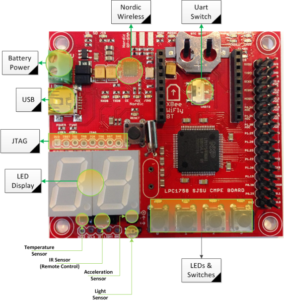
Much of the functionality of this project involved the use of the GPIO functionalities of the SJ One Board. During the timer set portion of the project, the GPIO ports use the switch buttons to manipulate the time as well as set the alarm. In both the timer set and countdown portions of the project, the 7-segment display and on board LEDs are used to display the amount of time left before the alarm goes off. For the remaining tasks of the project, the GPIO pins are used to connect to the H Bridge to control the direction of the wheels.
GPIO: Pin Connectivity Table
| Item | Port.Pin | Direction | Peripheral | Peripheral Port |
|---|---|---|---|---|
| 1 | P1.0 | Output | SJ One Board | LED0 |
| 2 | P1.1 | Output | SJ One Board | LED1 |
| 3 | P1.4 | Output | SJ One Board | LED2 |
| 4 | P1.8 | Output | SJ One Board | LED3 |
| 5 | P1.9 | Input | SJ One Board | SW0 |
| 6 | P1.10 | Input | SJ One Board | SW1 |
| 7 | P1.14 | Input | SJ One Board | SW2 |
| 8 | P1.15 | Input | SJ One Board | SW3 |
| 9 | P1.19 | Output | H Bridge | IN1 |
| 10 | P1.20 | Output | H Bridge | IN2 |
| 11 | P1.22 | Output | H Bridge | IN3 |
| 12 | P1.23 | Output | H Bridge | IN4 |
ADC
The ADC pins were used to interface the IR sensors with the SJ One Board. These sensors send an analog signal to the board which is then converted to a numeric value with the on-board function of the SJ One Board. This value is used to determine how close an object is to the front of the car which is used to control whether the car goes straight, turns left, or turns right.
ADC: Pin Connectivity Table
| Item | Port.Pin | Direction | Peripheral | Peripheral Port |
|---|---|---|---|---|
| 1 | P0.26 | Output | IR Sensor | Vo |
| 2 | P1.31 | Output | IR Sensor | Vo |
PWM
The PWM pins serve two purposes in the project. Its main function is to control the speed of the wheels of the alarm car. The speed is manipulated by changing the amount of time within the PWM frequency stays at high. The more time the wave is set at high, the faster the car moves. It is also used to sound the buzzer of the alarm car since it requires some sort of frequency to make a sound.
PWM: Pin Connectivity Table
| Item | Port.Pin | Direction | Peripheral | Peripheral Port |
|---|---|---|---|---|
| 1 | P2.2 | Output | H Bridge | DC Motor 1 |
| 2 | P2.4 | Output | H Bridge | DC Motor 2 |
| 2 | P2.5 | Output | Buzzer | - |
SJOne Board
L298N Dual H-Bridge
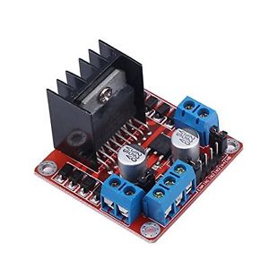
Using the L298N Dual H-bridge, it is powered by the 6.4V battery pack. The motors for the wheels are connected in pairs; the two on the left side of the car are connected together and the two on the right side of the car are connected together. This device uses both the GPIO and PWM functionalities of the SJ One Board to control the motion of the alarm car. The PWM pins control the speed of the car by manipulating the amount of high voltage sent to the motors in a give time frame. These pins are connected to the DC Motor Enable pins of the H-bridge. The GPIO pins are used to control the rotational direction of the wheels. Each pair of wheels has two pins on the L298N to interface with the four GPIO pins used with the module. IN1 and IN2 control the wheels on the left while IN3 and IN4 control the wheels on the right. When IN1 is high and IN2 is low, the wheels on the left move forward. In the reverse, those wheels move backwards. When IN3 is high and IN4 is low, the wheels on the right move forward, while with the reverse, they move backwards. If both wheels are moving forward, the car goes forward. When the wheels on the right go forward with the ones on the left go backward, the car turns left. When the wheels on the left go forward and the wheels on the right go backwards, the car turns right.
IR Sensor
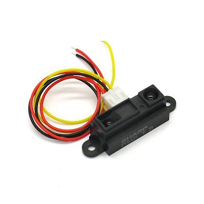
Each IR sensor has three wires. The three wires consist of a ground, power, and Vo. The power is supplied from the 6.4V battery box. The ground wire is tied to the common ground of the battery box and the SJOne board. The Vo wire is connected to appropriate GPIO pins from the SJOne board. When an object approaches the IR sensor, the voltage from the analog signal increases. This analog signal is converted using the built-in ADC via the ADC pins of the SJOne board. The alarm car uses two IR sensors to send data to the SJOne board. If either of the sensors exceed a pre-programmed value (in the case of this project, 900), then the car will turn. To ensure that the car takes a path with less obstacles, the board compares the readings from both of the sensors to determine which direction to turn. If the left sensor has a higher reading, the car turns left. If the previous statement is false, the car turns right.
Buzzer
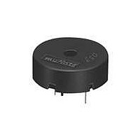
The buzzer has only two pins which are non-polarized when it comes to the connection to the SJOne board. One of the pins is connected to ground while the other pin is connected to a PWM pin of the SJOne board. Since sound comes in the form of waves, a PWM pin was used over the GPIO pin since it outputs a frequency. To keep the waves consistent, the PWM is set to 50% since the waves are consistent throughout.
Software Design
Show your software design. For example, if you are designing an MP3 Player, show the tasks that you are using, and what they are doing at a high level. Do not show the details of the code. For example, do not show exact code, but you may show psuedocode and fragments of code. Keep in mind that you are showing DESIGN of your software, not the inner workings of it.
Implementation
This section includes implementation, but again, not the details, just the high level. For example, you can list the steps it takes to communicate over a sensor, or the steps needed to write a page of memory onto SPI Flash. You can include sub-sections for each of your component implementation.
- ADC through the SJOne board
Testing & Technical Challenges
LCD Display
- Problem
Initially, the project called for the implementation of the 1602A v2 LCD Display to be used to display the time. The first issue with the board was the lack of datasheets available for the display. The closest datasheet for this display module was for v1.2, although that datasheet was vague. To minimize the number of pins needed for the LCD display, we decided on using it in 4-bit mode. The datasheet for v1.2 of the display showed that 4-bit mode was possible, but said little about implementation of the mode.
- Solution
As a workaround to this issue and to retain the alarm clock-like functionalities of the project, we decided to use the on board 7-segment display and LEDs to indicate the amount of time left before the alarm goes off. The 7-segment display represents the amount of minutes and the LEDs give an indication of the number of seconds before the alarm goes off. Within the final minute of the countdown before the alarm, the 7-segment display will show the time remaining before the alarm goes off and the car starts moving.
The workaround involves two tasks: one to set the timer and the other to count down to 0. In the timer set task, the user uses Switches 0 and 1 to set the time needed to elapse for the alarm to go off. Switch 0 increments the timer to 1 minute while Switch 1 resets the timer in case the user goes too far. When the user has the desired time set, Switch 2 is pressed which allows the RTOS to context switch to the countdown.
Stabilizing The Parts
- Problem
Since the car is moving, there is a chance that parts such as the sensors, SJ One Board, battery sources, and breadboards. Unless those parts of stabilized, there is a good chance that parts could fall off and disconnect pieces of the circuit. This issue is also bad since forceful removal of pieces could damage the pins and parts used during the lab. It would also negatively affect the functionality of the car since the IR sensors need to be stable in order to have the car avoid the obstacles.
- Solution
Our solution was to use a combination of double sided tape and zip ties to hold all of the pieces down. The breadboard and battery packs were held down by using the double sided tape. Since the SJ One Board is a more sensitive device due to all of the electrical components, multiple zip ties were used to tie down the board and keep it stable while the car is running. The IR sensors used a combination of both zip ties and the double sided tape to keep it stable and in place. The zip ties helped support the sensor while the double sided tape was used to keep the sensor stuck in place to keep the readings consistent.
Limited Chassis Size
- Problem
The entire project required many parts that needed to fit onto the chassis of the alarm car. The alarm car chassis is relatively small and has multiple wires hanging out of each of the components. This limited the amount of space to work with since the wires had to be loose enough to connect all of the pieces properly, but tight enough to not get caught in the wheels when the car is running. Much like the previous issue listed, this could damage the parts and affect the completion of the project.
- Solution
The solution was to make use of both layers of the chassis. In the bottom layer, the AA Battery holder and power bank were placed to save space on the top layer. Since both of these connections to the boards on the top layer were simple, they were placed on the bottom with their respective wires going through the slit on the top layer to easily power up the devices. The IR sensors were also placed on the bottom layer to save space up front on the car. The breadboards were placed towards the back with the SJ One board resting on top and in the middle. While this uses up some breadboard space, it leaves enough space for all of the connections to be made. With enough space, the H Bridge was placed towards the front of the chassis to easily connect to the motors, SJ One Board, and battery pack.
Conclusion
Conclude your project here. You can recap your testing and problems. You should address the "so what" part here to indicate what you ultimately learnt from this project. How has this project increased your knowledge?
Project Video
Upload a video of your project and post the link here.
Project Source Code
References
Acknowledgement
This project could not have been completed without the guidance and assistance of the following people:
- Dr. Haluk Ozemek
- Preetpal Kang
- Charles MacDonald
- Praveen Prabhakaran
References Used
Datasheets
Links
Appendix
You can list the references you used.


