F16: Titans
Contents
Project Title
Autonomous Navigating RC Car
Abstract
This section should be a couple lines to describe what your project does.
Objectives & Introduction
Show list of your objectives. This section includes the high level details of your project. You can write about the various sensors or peripherals you used to get your project completed.
Track Progress in KanBan
Team Members & Responsibilities
- Master Controller
- Haroldo Filho
- Urvashi Agrawal
- Motor Controller & I/O Module
- Sant Prakash Soy
- Saketh Sai Narayana
- Kayalvizhi Rajagopal (LCD)
- GPS/Compass Module
- Yang Thao (GPS)
- Daamanmeet Paul (Compass)
- Sensors
- Kayalvizhi Rajagopal
- Communication Bridge/Android App
- Parth Pachchigar
- Purvil Kamdar
Project Schedule
Legend: Motor & I/O Controller , Master Controller , Communication Bridge Controller, Geographical Controller, Sensor Controller , Team Goal
| Week# | Start Date | End Date | Task | Status |
|---|---|---|---|---|
| 1 | 09/13/2016 | 09/20/2016 |
|
Completed |
| 2 | 09/21/2016 | 09/27/2016 |
|
Completed |
| 3 | 09/28/2016 | 10/04/2016 |
|
Completed |
| 4 | 10/05/2016 | 10/11/2016 |
|
Completed |
| 5 | 10/12/2016 | 10/17/2016 |
|
Completed |
| 6 | 10/18/2016 | 10/24/2016 |
|
Completed |
| 7 | 10/25/2016 | 10/31/2016 |
|
Completed |
| 8 | 11/1/2016 | 11/7/2016 |
|
Completed |
| 9 | 11/8/2016 | 11/14/2016 |
|
In Process |
| 10 | 11/15/2016 | 11/21/2016 |
|
Not Started |
| 11 | 11/22/2016 | 11/28/2016 |
|
Not Started |
| 12 | 11/22/2016 | 11/28/2016 |
|
Not Started |
| 13 | 11/29/2016 | Presentation date |
|
Not Started |
Parts List & Cost
| Item# | Part Desciption | Vendor | Qty | Cost |
|---|---|---|---|---|
| 1 | RC Car - Traxxas 1/10 Slash 2WD | Amazon | 1 | $189.95 |
| 2 | Traxxas 2872X 5000mAh 11.1V 3S 25C LiPo Battery | Amazon | 1 | $56.99 |
| 3 | Traxxas 7600mAh 7.4V 2-Cell 25C LiPo Battery | Amazon | 1 | $70.99 |
| 4 | Traxxas 2970 EZ-Peak Plus 4-Amp NiMH/LiPo Fast Charger | Amazon | 1 | $35.99 |
| 5 | Bluetooth 4.0 BLE Bee Module (Dual Mode) | Robotshop | 1 | $19.50 |
| 6 | 4D systems 32u LCD | 4D systems | 1 | $41.55 |
| 7 | LV Maxsonar EZ0 Ultrasonic sensors | Robotshop | 5 | $124.75 |
| 8 | Devantech SF05 Ultrasonic sensor | Provided by Preet | 1 | Free |
| 9 | Venus GPS with SMA connector | Amazon | 1 | $49.95 |
| 10 | SMA Male Plug GPS Active Antenna | Amazon | 1 | $9.45 |
| 11 | Wire wrapping board | Radio shack | 1 | $20.0 |
| 12 | CAN tranceivers | Digikey | 10 | $10.0 |
| 13 | SJOne Boards | Provided by Preet | 5 | $400.0 |
DBC File Implementation
- The following is the DBC file of the project.
VERSION ""
NS_:
 NS_DESC_
 CM_
 BA_DEF_
 BA_
 VAL_
 CAT_DEF_
 CAT_
 FILTER
 BA_DEF_DEF_
 EV_DATA_
 ENVVAR_DATA_
 SGTYPE_
 SGTYPE_VAL_
 BA_DEF_SGTYPE_
 BA_SGTYPE_
 SIG_TYPE_REF_
 VAL_TABLE_
 SIG_GROUP_
 SIG_VALTYPE_
 SIGTYPE_VALTYPE_
 BO_TX_BU_
 BA_DEF_REL_
 BA_REL_
 BA_DEF_DEF_REL_
 BU_SG_REL_
 BU_EV_REL_
 BU_BO_REL_
 SG_MUL_VAL_
BS_:
BU_: DBG MASTER GPS MOTOR SENSOR APP
BO_ 1 APP_START_STOP: 1 APP
 SG_ APP_START_STOP_cmd : 0|8@1+ (1,0) [0|0] "COMMAND" MASTER
BO_ 16 SENSOR_DATA: 3 SENSOR
 SG_ SENSOR_left_sensor : 0|8@1+ (1,0) [0|0] "Inches" MASTER,APP
 SG_ SENSOR_middle_sensor : 8|8@1+ (1,0) [0|0] "Inches" MASTER,APP
 SG_ SENSOR_right_sensor : 16|8@1+ (1,0) [0|0] "Inches" MASTER,APP
BO_ 32 MASTER_HB: 2 MASTER
 SG_ MASTER_SPEED_cmd : 0|8@1+ (1,0) [0|0] "" SENSOR,MOTOR,GPS,APP
 SG_ MASTER_STEER_cmd : 8|8@1+ (1,0) [0|0] "" SENSOR,MOTOR,GPS,APP
BO_ 65 GPS_Data: 8 GPS
 SG_ GPS_READOUT_valid_bit : 0|1@1+ (1,0) [0|1] "" MASTER,MOTOR,APP
 SG_ GPS_READOUT_read_counter : 1|6@1+ (1,0) [0|60] "" MASTER,MOTOR,APP
 SG_ GPS_READOUT_latitude : 7|28@1+ (0.000001,-90.000000) [-90|90] "" MASTER,MOTOR,APP
 SG_ GPS_READOUT_longitude : 35|29@1+ (0.000001,-180.000000) [-180|180] "" MASTER,MOTOR,APP
BO_ 66 COMPASS_Data: 2 GPS
 SG_ COMPASS_Heading : 0|9@1+ (1,0) [0|0] "Degree" MASTER,APP,MOTOR
BO_ 67 GEO_Header: 3 GPS
 SG_ GPS_ANGLE_degree : 0|12@1+ (0.1,-180) [-180.0|180.0] "Degree" MASTER,MOTOR,APP
 SG_ GPS_DISTANCE_meter : 12|12@1+ (0.1,0) [0.0|400.0] "Meters" MASTER,MOTOR,APP
BO_ 48 MOTOR_STATUS: 3 MOTOR
 SG_ MOTOR_STATUS_speed_mph : 0|16@1+ (0.001,0) [0|0] "mph" MASTER,APP,MOTOR
CM_ BU_ MASTER "The master controller driving the car";
CM_ BU_ MOTOR "The motor controller of the car";
CM_ BU_ SENSOR "The sensor controller of the car";
CM_ BU_ APP "The communication bridge controller of car";
CM_ BU_ GPS "GPS and compass controller of the car";
CM_ BO_ 100 "Sync message used to synchronize the controllers";
BA_DEF_ "BusType" STRING ;
BA_DEF_ BO_ "GenMsgCycleTime" INT 0 0;
BA_DEF_ SG_ "FieldType" STRING ;
BA_DEF_DEF_ "BusType" "CAN";
BA_DEF_DEF_ "FieldType" "";
BA_DEF_DEF_ "GenMsgCycleTime" 0;
BA_ "GenMsgCycleTime" BO_ 32 100;
BA_ "GenMsgCycleTime" BO_ 16 100;
BA_ "GenMsgCycleTime" BO_ 48 100;
BA_ "GenMsgCycleTime" BO_ 65 100;
BA_ "GenMsgCycleTime" BO_ 66 100;
Sensor Controller
Design & Implementation
The main purpose of the sensor controller is Obstacle avoidance and one of the straight forward way to achieve the goal is to use an Ultrasonic sensor.
Sensor controller being the “eye” of the project, lot of thoughts were put into deciding the right sensor to serve the purpose of obstacle avoidance. Considering the factors of reliability and cost, Maxbotix EZ0 ultrasonic sensor is chosen to be left and right sensors. EZ ‘0’ model is selected because it has the widest beam coverage of all the Maxbotix EZ series sensor models. Devantech SF05 ultrasonic sensor is selected for the middle sensor. A different model is used for middle sensor because of its different frequency, which avoids interference between sensors.
The sensors are mounted and tested at different angles so that the front three sensors cover a wide area, without leaving any dead or uncovered region.
Hardware Design
The sensors are interfaced using Port 2 GPIO pins of the microcontroller. The sensors require 5V power supply, which was provided from the main board’s supply. The trigger input to the sensors and the PWM output are interfaced to the GPIO pins as shown below in table. The pins for each sensor are chosen in such a way that it would not tangle each other while physically connecting them on the main board. CAN 1 of the SJOne board is connected to the CAN bus of the car which is also shown in the table below.
| Pin Name | Function |
|---|---|
| P2_0 | Trigger for left sensor |
| P2_1 | Echo for left sensor |
| P2_2 | Trigger for middle sensor |
| P2_3 | Echo for middle sensor |
| P2_4 | Trigger for right sensor |
| P2_5 | Echo for right sensor |
| P0_1 | CAN Tx |
| P0_2 | CAN Rx |
3D Printing Design
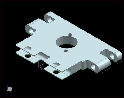
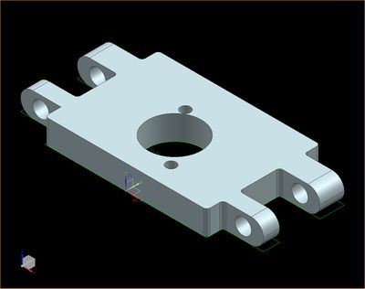
Sensors are required to be placed at a minimum height of 18 cm from the ground and at a tilt of 5 degrees to avoid ground reflections. A proper mount is required to place them at adjustable angles and heights. Hence the mounts are 3D printed using the below 3D deigns. The heights are adjustable by adding mode standoffs and the angle is adjustable by using the bottom screws.
Hardware Interface
The sensors are interfaced using GPIO pins. CAN 1 of the sensor controller is interfaced to the CAN bus of the car. Below diagram shows the hardware interface between the micro controller, sensors and the CAN bus.
Software Design
Software is designed such that the no two sensors of same type/model close by will be triggered simultaneously, so as to avoid interference with each other. Since the left and right sensor are of the same model, they are triggered sequentially, every 50 ms. The Maxbotix sensors cannot be triggered faster than 49 ms because it takes the sensors a maximum of 49 ms to pull down the PWN pin low when there is no obstacle for 6 meters or 254 inches. If triggered sooner, the reflected waves from the sensor will interfere with the next sensor, giving unpredictable values. The middle sensor and the back sensor are triggered every 50 ms. Hence we get all 4 sensor readings in 100 ms. The triggering of sensors is handled in 1 ms task, but with the check to trigger only every 50 ms. Refer the below datasheets for timing information for triggering and detailed working of both sensor models.
Maxbotix EZ0: http://www.maxbotix.com/documents/LV-MaxSonar-EZ_Datasheet.pdf
Devantech SF05:https://www.robot-electronics.co.uk/htm/srf05tech.htm
Implementation
Algorithm
1. Initialize the trigger pins as output and PWM pins as input
2. Configure the PWM pins for falling edge interrupt
3. Trigger left and middle and back sensor and start the timer for all three
4. Wait for echo from all of them
5. When echo is received, calculate the distance in inches using the below formula
Distance = (stop time – start time)/147
6. Trigger right and middle sensor and start the timer for both & repeat from step 4
7. Broadcast the sensor values on CAN bus
Below is the sample interrupt callback function(ISR) to calculate the distance of obstacle.
The flowcharts shown describes in detail on how each sensor is triggered and broadcasted over CAN every 100 ms.
Testing & Technical Challenges


