S16: Sprinkler
Contents
Grading Criteria
- How well is Software & Hardware Design described?
- How well can this report be used to reproduce this project?
- Code Quality
- Overall Report Quality:
- Software Block Diagrams
- Hardware Block Diagrams
- Schematic Quality
- Quality of technical challenges and solutions adopted.
Smart Sprinkler System
Abstract
Agriculture consumes the majority of freshwater in the United States, and with growing pressure to conserve water in the agriculture sector, people are looking for newer and better methods in water conservation. The objective of this project is to implement a residential irrigation system that utilizes IoT (Internet of Things) concepts to control and conserve water usage. The irrigation system consists of a microcontroller activates 24 VAC electrical valves to control the water flow of sprinkler devices. The project will consist of using one SJone board that act as an irrigation scheduler that dictates periodic activation of sprinkler devices. The scheduler obtains weather and forecast readings from the internet and use it to make changes (if any) to the scheduling of irrigation events. A relay circuit connected to the SJone board allows the scheduler to turn on/off sprinkler devices. Soil moisture sensors were deployed to local areas to send soil conditions of plants to the scheduler. In a scheduled event, the scheduler check the soil conditions of the local area and determine if it should activate sprinkler devices. The user involvement is to configure the scheduler to activate the sprinkler devices at which specific days and times, but once that is set, the scheduler became automated and acts on its own without requiring additional user’s involvement. The attractive function of the scheduler is that it behaves “smartly” by following a set of predefined rules.to control the irrigation system. For example, on a rainy day, the scheduler will delay or remove a scheduled irrigation event. By having a smart irrigation system in the home, the user will have an easier time saving and conserving water much more efficiently.
Objectives & Introduction
Show list of your objectives. This section includes the high level details of your project. You can write about the various sensors or peripherals you used to get your project completed.
Team Members & Responsibilities
- Phi Lam
- Scheduler Task
- Order hardware parts/ hose fittings
- Relay Circuit/Sprinkler Task
- Documentation/Diagrams
- Alejandro Reyna
- Relay Circuit/Sprinkler Task
- Moisture Sensor Task
- Hardware Setup
- Documentation/Diagrams
- Sang Nguyen
- WiFi Module Task
- Hardware Setup
- Documentation
Schedule
The point of the schedule is for readers to assess how to pace themselves if they are doing a similar project.
| Week# | Start Date | End Date | Task | Status | Completion Date |
|---|---|---|---|---|---|
| 1 | 04/03/2016 | 04/09/2016 | Project Idea confirm, ordering project parts | Complete | 04/11/2016 |
| 2 | 04/10/2016 | 04/16/2016 | Begin conceptual design of code and schematic | Complete | 04/16/2016 |
| 3 | 04/17/2016 | 04/23/2016 | Work on designing code for basic sprinkler system and set up physical sprinkler system. | Complete | 04/23/2016 |
| 4 | 04/24/2016 | 04/30/2016 | Enhance sprinkler system code to work with moisture sensor, refine the physical sprinkler system. | Complete | 04/30/2016 |
| 5 | 05/01/2016 | 05/07/2016 | Connect the sprinkler system to the internet | In process | 05/07/2016 |
| 6 | 05/08/2016 | 05/14/2016 | Finish internet connection and get a box to house the components, complete project | In process | 05/14/2016 |
| 7 | 05/14/2016 | 05/24/2016 | Debug and refine project and demo. | In process | 05/14/2016 |
Parts List & Cost
Relay Circuit
| Item | Quantity | Cost | Comments |
|---|---|---|---|
| 3 VDC Power Relay | 1 | $3.50 | Philmore 86-103 |
| Transistor | 1 | $0.08 | NPN Bipolar P2222A |
| 24 VAC Transformer | 1 | $16.25 | |
| 24 VAC Electrical Valve | 1 | $12.97 |
Irrigation Materials (from Home Depot)
| Item | Quantity | Cost | Comments |
|---|---|---|---|
| 15 ft. Water Hose | 1 | $7.97 | |
| Adapters, Fittings for Hose | 4 | $14.00 | |
| Teflon Tape | 1 | $1.47 | |
| Gear Drive Sprinkler | 1 | $7.97 |
Miscellaneous
| Item | Quantity | Cost | Comments |
|---|---|---|---|
| Wifi Wireless Transceiver | 1 | $6.55 | ESP8266 ESP-01 |
| Soil Moisture Sensor | 5 | $7.99 | |
| 25 ft. Cord Extension | 1 | $9.97 |
Design & Implementation
The Smart Sprinkler design was based on the idea that a normal sprinkler system would be enhanced to check the weather, and adjust its watering schedule. Also, the sprinkler would be aware of days that are meant for watering, if cities have water usage laws. A moisture sensor was added to further allow watering decisions to the sprinkler.
Hardware Design
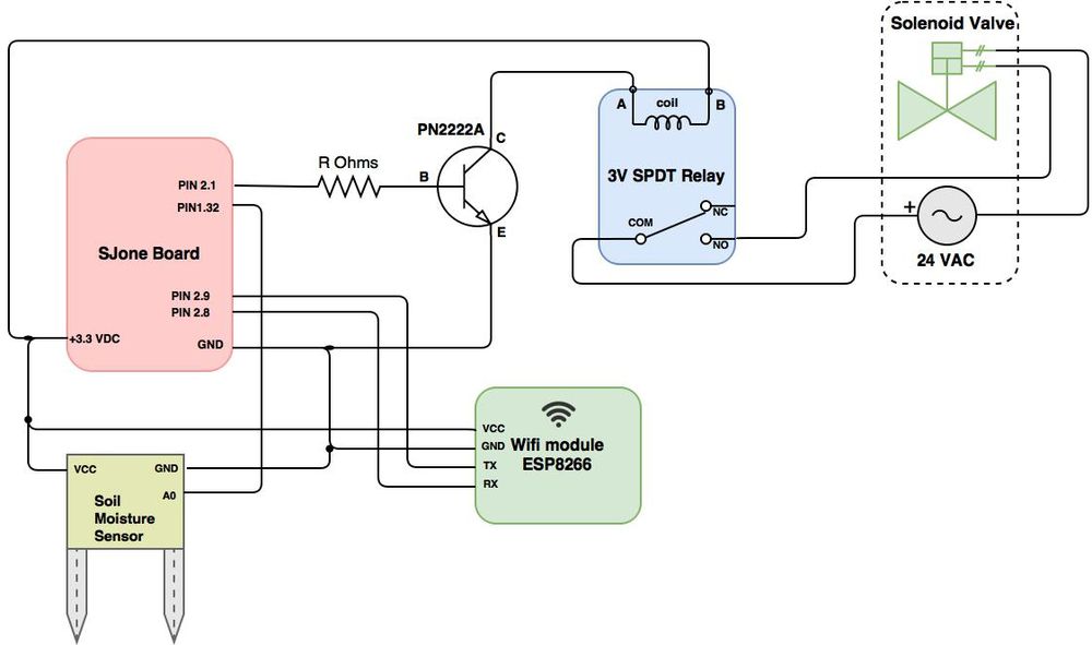
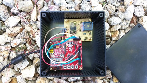
The hardware components that were used were a SJOneBoard, an ESP8266 WiFi module, a 24 VAC solenoid valve, a 3v relay, and an analog soil moisture sensor. The relay, moisture sensor, and WiFi module were powered by the 3.3v and GND output pins of the SJOneBoard respectively.
Figure 1 above show the project's hardware system schematic. The SJone board control the relay through GPIO and a NPN transistor. The relay control the ON/OFF switch of the solenoid valve. The SJone board use the wifi module, ESP8266, to obtain data such as current time and weathers through the internet. The SJone board also use the soil moisture sensor to obtain soil moisture data from its physical settings.
Figure 3 on the left show what the transistor-relay-solenoid valve circuitry looks like upon receiving a low voltage level from a GPIO of SJone board. The base of the NPN transistor (B) received 0V which means the transistor is in cutoff mode - no current flows between the Collector (C) and Emitter (E) meaning an open circuit between C and E. The transistor is basically an open switch at the moment. This means that there is no current flow between from Terminal B to Terminal A of the relay, and so the coil in the relay is not energized. When the coil is at rest or not energized, the common (COM) pole by default connects to the Normally Closed (NC) terminal. Since one lead of the solenoid valve connects to the Normally Open (NO) terminal of the relay, an open circuit is present between the solenoid valve and its 24 VAC source, thus the sprinkler is deactivated.
Figure 4 on the left also shows the transistor-relay-solenoid valve circuitry, but this time with 3.3V being applied to the base of the transistor. This NPN transistor received high enough voltage to enter saturated mode - current flow from Collector to Emitter which resembles a short circuit. This means that there is also current flow from Terminal B to Terminal A of the relay that creates an electromagnetic field, which attracts a lever in the switch, causing COM to break contact from NC terminal and make contact with NO terminal. Now there is a complete circuit between the solenoid valve and its 24 VAC source, thus the sprinkler is activated.
Hardware Interface
The WiFi module was connected to the UART bus of the SJone board at pins 2.8 and 2.9. The communication works on a single read and single receive. The internet connection was needed to get current time, user schedule, and weather information.
- Pin 2.8 is the SJone's TX2 pin that connects to the ESP8266's RX pin to transfer data out out from SJone board to ESP8266.
- Pin 2.9 is the SJone's RX2 pin that connects to the ESP8266's TX pin to receive data in from ESP8266 to SJone board.
- Since ESP8266 can operate at 3.3V, its VCC connects to +3.3VDC of SJone board.
The 3V SPDT Relay was controlled by SJone's GPIO pin, 2.1. The pin would output 3.3v to trigger the relay circuit to turn on the sprinkler. A NPN transistor was used to act as a switch to control current flow from Terminal B to Terminal A to energized/de-energized the coil in the relay module.
- Pin 2.1 is SJone's output GPIO pin that connects to the base (B) of the PN2222A transistor. A current-limiting resistor is placed between the connection.
- The Collector (C) is the positive lead of PN2222A that connects to Terminal A of the relay.
- Since the relay is 3V sensitive, its Terminal B connects to +3.3VDC of SJone board.
- The Emitter (E) is the negative lead of PN2222A that connects to the GND of SJone board.
The Solenoid Valve was controlled by the 3V SPDT Relay module, which connects/disconnects the Solenoid Valve from the 24 VAC source.
- One lead of the Solenoid Valve connects to Terminal COM (Common) of the relay. The COM terminal is connected to Terminal NC (Normally Closed) when the relay's coil is not energized.
- The other solenoid lead connect to one end of the 24 VAC source, which the other end of 24 VAC source connect to the Terminal NO (Normally Open) of the relay. When the relay's coil is energized ( current flow from Terminal B to Terminal A), Terminal COM connects to Terminal NO of the relay.
The moisture sensor was used to read the levels of moisture in the lawn, where the sprinkler would be utilized. The sensor was connected to Pin 1.30 of the board.
Software Design
Tasks Communications
The overall software design of the system used several tasks to accomplish its objective. Below are descriptions of each task and its responsibility.
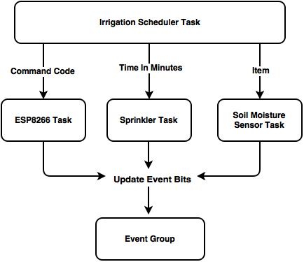
The Figure 4 above shows what data are transferred between tasks at the top level. The Irrigation Scheduler Task is the main task that dictates and controls the overall system by providing instruction to other tasks. For example, the Irrigation Scheduler Task send command codes that instruct the ESP8266 Task to perform certain functions such as connecting to wifi and obtain current time or weather data. The Irrigation Scheduler also instruct the Sprinkler Task to activate the sprinkler device for certain amount of minutes. Finally, when the scheduler need to obtain soil moisture reading, it instruct the Soil Moisture Sensor Task to take readings from its sensor. After completing its work, each task, excluding the scheduler, update event bits to notify the scheduler of their status.
Scheduler Task
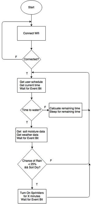
The goal of the Scheduler Task is to control and dictate when and if the water sprinkler should be activated. The scheduler take the role of the master task that provide instruction to other lower-tier class to perform certain functions. From Figure 5, the flowchart diagram show the the steps the scheduler performs to determine if there were conditions met to activate of the water sprinkler. After connecting to the WiFi, the scheduler obtain current time and user schedule and use those time value to determine if it's time to turn on the sprinkler based on the user scheduler. If the current time is not met with the user schedule time, the scheduler sleeps for the remaining time. If it is determined that the user schedule time is met, the scheduler get updated values of weather data and soil moisture data and use those value to smartly determine if activation of water sprinkler is required. The scheduler repeat the same procedure in a loop, defining its useful automative feature.
ESP8266 Task
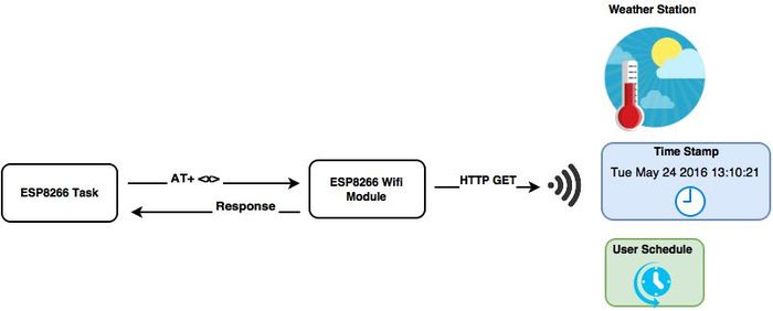
The goal of the ESP8266 Task is to process the command code provided by the scheduler and send the command over UART interface to control the ESP8266 Wifi Module. This task control the WiFi module through AT+<x> commands, where <x> is the parameter that define certain functions such as joining an access point, creating TCP connection to server, send data, etc. For each command sent over to the WiFi module, the WiFi provide a response back of the query status or data depending on which type of commands used. The main usage of the ESP8266 task is to obtain such data including weather data, current time-stamp of location, and user's schedule through webservice API calls from Thingspeak and weather station.
Soil Moisture Sensor Task
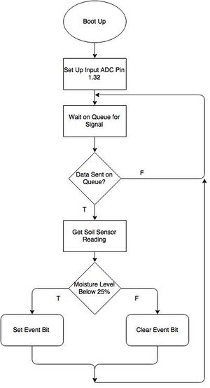
The goal of the moisture sensor task was to enhance the functionality of the Sprinkler system. The moisture sensor outputted an analog signal with respect to the "resistance" between both probes. This signal was converted to a readable input by accounting the steps size, which was 4096 (2^12), due to the number of bits used in the signal. This information was sent and stored in the task to check the moisture level. A level below 25% was considered to by dry and if the value that was read upon the task waking up, an event bit would be set. This bit indicated to the irrigation scheduler task that the dirt was dry and needed to be watered. In the end, this adds the functionality of being efficient of when to water a lawn.
Sprinkler Task The goal of the Sprinkler task is to activate the sprinkler device as instructed by the scheduler. The item received on the its queue define the duration of time in minutes to keep the sprinkler device active. For example, if the scheduler sent an item = 1 to the sprinkler's queue, then the sprinkler task will activate the sprinkler device for 1 minute long. The sprinkler task set an event bit to let the scheduler know that the sprinkler device is active, and when the sprinkler device is turned off, the event bit is then cleared. We do this just as a sanity check to make sure the sprinkler device is not held active after the time duration passes.
Schedule Time
3:54 PM
Implementation
Queues and Tasks
Since the scheduler act as the master task that controls the system, other lower-tier task must wait for instruction provided by the scheduler. To accomplish this master-slave scheme, queues were used as a mean of communication tool between the scheduler task and its lower-tier tasks. The lower-tier tasks (ESP82566, Soil Moisture Sensor, and Sprinkler Task) first wait on an empty queue, where it is waiting for the scheduler to send an item over to their respective queue. The item being sent over provide instruction to the task that is waiting on the queue (i.e., a command code to the ESP8266 task or watering time (in minutes) to the Sprinkler task).
Event Group
The scheduler acting as the master task should also want to know the status of its slave task, and this was accomplished using event groups. An event group was used to convey status of tasks and help with syncing the scheduler with other tasks. The scheduler test certain bits value to see which events are active or which tasks has completed its work. Upon sending a command to a task, the scheduler entered a Blocked state to wait for a specified bit or group of bits to be set. By doing this, the scheduler transition into a Blocked state in order to not consume any processing time and allow other lower priority tasks to run. For example, after the scheduler send a command code to the ESP8266 Task, it wait for Bit 0 to be set. By doing this, the scheduler wait until the ESP8266 Task finished doing work. After Bit 0 is set, the scheduler knows that the current time and weather data are updated to its newest value and could proceed further on to the next step.
As mentioned above, the ESP8266, Soil Moisture Sensor Task, and Sprinkler Task modifies the event bits to notify the scheduler of its status. Below is the table describing the meaning of each event group bits and which task are responsible for modifying the bit.
Table: Event Group Bits
| Bit# | Description | State 0 | State 1 |
|---|---|---|---|
| 0 | ESP8266 Task: is it finish doing work? | In Process | Done |
| 1 | ESP8266 Task: any wifi error from command code?? | No Error / Successful transaction | Error |
| 2 | Moisture Sensor Task: is it finish doing work? | In Process | Done |
| 3 | Moisture Sensor Task: what is the soil moisture level? | Soil moisture level is wet / No need to water. | Soil moisture level is dry / Need to water. |
| 4 | Sprinkler Task: is it finish doing work? | In Process | Done |
| 5 | Sprinker Task: is the sprinkler device turned on? | Device is off | Device is on |
Scheduler
Here is the process describing the steps the schedule take to initialize upon boot up and what steps to take to send an instruction to a slave task.
1. initialization
- create queues for ESP8266 Task, Soil Moisture Sensor Task, and Sprinkler Task
- create event group bits
2. send instruction to slave task (using ESP8266 Task as example)
- modify item value (espCommand set to 4, espCommand = 4)
- send item to queue (send espCommand to queue, xQueuesend()
- wait for event group bit to set (wait for Bit 0 to set, xEventGroupWaitBits()
- after returning from xEventGroupWaitBits(), proceed to further to perform other functions (ie find_RemainingTime() )
ESP8266 Task
Here is the process describing the steps the ESP8266 Task take to process the command code.
1. Got command code from scheduler
- process command code (ie if command = 2, execute updateweather() )
- perform wifi function (ie function calls to updateweather() )
2. Performing wifi function
- check if wifi is connected
- establish TCP connection to server host
- send data buffer size
- send HTTP GET request
- receive data from RX buffer
- update system struct members
3. Update event bit
- if WiFi error set Bit_1
- set Bit_0, signaling scheduler this task has finish doing work
Sprinkler Task
Here is the process describing the steps the Sprinkler task take when it received an item from the scheduler
1. Got water time from scheduler
- convert minutes to ms
- set event Bit_5 to signal scheduler that sprinkler device is active
- set GPIO Pin 2.1, activating sprinkle device
- wait for x minutes
2. After x minutes
- clear GPIO Pin 2.1, deactivating the sprinkler device
- clear event Bit_5 to signal scheduler that sprinkler device
- set event Bit_4 to signal scheduler this task has finished doing work
Soil Moisture Sensor Task
Here is the process describing the steps the Soil Moisture Sensor Task takes upon receiving an item from the scheduler
1. Got item from scheduler
- take reading from adc04
- convert reading to readable input (i.e., digital level = ( vfs / 2^n ) * Analog reading ) where n is number of bits used for adc04
2. Logic comparison
- if level >= 2.4 V, set event Bit_3 signaling scheduler that soil is dry
- else clear event Bit_3 signaling scheduler that soil is moist
- set event Bit_2 signaling scheduler that this task has finished doing work
Testing & Technical Challenges
Technical Challenges
Getting Proper Hose Fittings
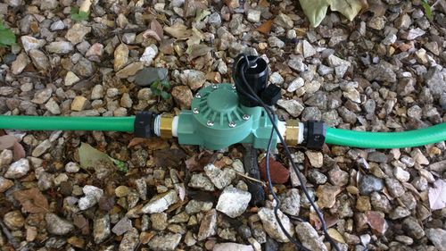
Since our group didn’t have any hoses already installed at our own place, we have to buy the necessary parts from scratch to setup a proper water hose. This is a challenge for us since we didn’t have any mechanical background regarding fitting hoses. It is recommended to consult with experts first before buying any parts. We suggest going to Home Depot to consult with their experts and get the necessary parts there. There are many variations of hose fittings: depending on what parts you already have and which part you started building with. For us, we started with a solenoid valve and proceed from there in getting parts that satisfy the valve’s requirement. Here are the steps we took to complete a water hose setup:
- Started with the solenoid valve, obtain 2 set of water hoses to attach to both end of the valve. Obtain any adapters/fittings to connect both end of the valve to hoses if required.
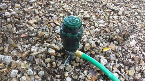
- Obtain a water sprinkler device to connect to one end of a water hose. Obtain any adapters/fittings to connect the sprinkler device to a water hose.
- Make sure the other end of the water hose fit with the water faucet that is used as the water source for your project. Obtain any adapters/fittings if required.
Water Leakage
After buying all the necessary parts to fit the water hoses with the electrical valve, sprinkler device, and water faucet, it was time to connect all these parts together and test out the connections. There were issues encountered with water leaking out from a few connecting joints due to combination of loose fittings and high water pressure. Attempts to resolve this particular issue include using PTFE tapes or thread seal tapes to ensure a tighter fittings on the adapters. Other precautions were made including isolating electrical components away from possible contacts to leaking waters.
Challenges with the WiFi Module
- Coding the Wifi Module proved alot more daunting than originally expected. At first, there was issues with the device not being powered properly. This part was resolved by routing all the pins that weren't being used to 3.3v.
- The second challenge was establishing a communication. the receive data was checked before it was available and the timeouts had to be adjusted.
- Once the Wifi Module was working, there is another challenge in reading data from a webpage. Parsing the data was a hassle because the original websites that were checked for weather werent formatted nicely. Once this was debugged, the information was successfully parsed, the weather data was sent to the irrigation scheduler.
- Attempts to connect the wifi module to SJSU's campus wifi (SJSU_premier) proved to be challenging. SJSU_premier uses WPA2 Enterprise and Protected EAP (PEAP) for user authentications, and since the ESP8266 wifi module doesn't support these configurations, another workaround was used to connect the ESP8266 to the access point when working on SJSU campus. Alternatively, wifi-hotspot was created by using PDAnet and Connectify softwares, which can serve as the access point for ESP8266 to connect to the internet.
Testing
Hardware Testing
- Testing on the water hose fitting was done early to ensure that the proper adapters and fittings were correct. By doing this early, the team found issue in water leakage from a few joints of the hose and was quick to apply corrections to the problem.
- Testing the solenoid valve involve attaching one valve's end to the water faucet and applying a switch through the relay to see if water flow through the valve. For the relay circuit, applying 3.3V to the base of the NPN transistor which energizes the coil and the contacts were switched to the NO terminal, thus creating a clicking sound.
- The soil moisture sensor was also tested to see the range of readings when the sensor is damped in wet soil or placed in dry soil, allowing us to determine the threshold level for what is considered moist or dry.
Software Testing
- Testing the ESP8266 Task involved sending different parameters in the AT+<x> field to make sure WiFi connection were established correctly. After connecting to a desired access point, the task run ping commands to test if it can sent data and receive the ping response back from a server. A successful ping response back tell us that the ESP8266 WiFi module is indeed communicating properly through the internet. There were also test on what responses the WiFi module received back based on different commands being sent over. This was required since we want the ESP8266 task to proceed further sending additional commands only if the earlier command yield the expected responses back from the ESP8266 WiFi module (i.e., we don't want any ERROR message response back).
Conclusion
This project was a good way to dive into how FreeRTOS works. Our team was able to create a basic smart sprinkler system. We learned how to implement submodules into the SJOne board. We tackled on the problems of figuring out how to get the Wifi module to work. This was the toughest part, as the concept was understood of how it uses UART. It was working with the Wifi module and getting the correct data to read back was the issue.
If we had more time with the project, we would have wanted to implement a website to be the way to control the system. The website would be able to show data of the usage of the sprinkler system. We would have wanted to show off how much water has been used in certain time intervals, calculate averages and try to provide as much data to the user as possible. An LCD screen would have been great to implement in order to see how the device was functioning.
Project Video
Project Source Code
References
Acknowledgement
We would like to thank Preetpal Kang, Dr. Ozemeck and all the fellow engineering students who helped out with this project, both with their educational and moral support.
References Used
List any references used in project.
SJ One Board LPC 1758 Schematics
LPC176x/5x User Manual
WiFi Wireless Transceiver ESP8266
3 VDC Power Relay
NPN P2222A Transistor
Appendix
You can list the references you used.
