F15: Electronic Piano
Contents
Grading Criteria
- How well is Software & Hardware Design described?
- How well can this report be used to reproduce this project?
- Code Quality
- Overall Report Quality:
- Software Block Diagrams
- Hardware Block Diagrams
- Schematic Quality
- Quality of technical challenges and solutions adopted.
Electric Piano with Motion Controlled LED Keys
Abstract
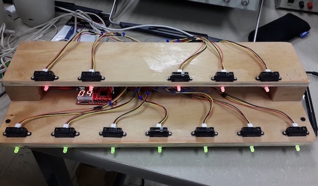
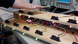
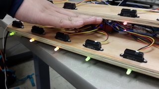
The purpose of this project is to design and build a motion controlled electronic piano powered by an SJ-One Board. Users will be able to play the notes of a piano using IR proximity sensors as keys. At activation, the key's LED will light up. The number of keys of the piano will cover one key short of an octave; however, the piano provides users the capability to change (offset) the notes across other ranges.
Objectives & Introduction
The objective of this project is to design and build a multi-keyed motion controlled electronic piano. The piano will feature 12 IR proximity sensors to act as motion activated keys, a real-time MIDI decoder to play piano notes, and LEDs that activate along with the activation of its associated key. The electronic piano will utilize FreeRTOS multitasking environment to simultaneously sample values from multiple IR proximity sensors, analyze the obtained values, then play piano notes according to the active state of the IR keys.
1. Read an IR sensor's value using an external ADC
2. Write a software to read multiple IR sensors and play different piano notes using a MIDI decoder
3. Assemble a range of IR sensors to function as piano keys and an array of ADCs to read all IR sensors
4. Build a wooden frame and mount the control circuits and IR sensors
5. Integrate LEDs to each key and control the LEDs using an LED driver
Team Members & Responsibilities
- Jason Tran
- Design and write the software
- Design and build the power circuit and ADC circuit
- Arthur Nguyen
- Design and build the wooden frame
- Mount boards and IR keys onto the wooden frame
- Design and build the LED circuit
Schedule
Show a simple table or figures that show your scheduled as planned before you started working on the project. Then in another table column, write down the actual schedule so that readers can see the planned vs. actual goals. The point of the schedule is for readers to assess how to pace themselves if they are doing a similar project.
| Week# | Date | Task | Actual |
|---|---|---|---|
| 1 | 10/30 | Project proposal | Completed. Discussed project design of both hardware and software. |
| 2 | 11/6 | Part testing and project outline | Completed testing Sharp IR sensor and MIDI controller interface. |
| 3 | 11/13 | Order parts | Completed order of essential parts including VS1053, short IR sensors,IR jumper wires, and analog to digital converters. Completed software. |
| 4 | 11/20 | Setup all keys with sound. | Completed playing sounds with key activation. |
| 5 | 11/27 | Volume control and power circuit. | Completed. |
| 6 | 12/4 | Combine circuits and start mounting system. | Ordered LEDs and LED driver. Started mounting system onto board. |
| 7 | 12/11 | Build LED circuit and implement software for LEDs. Combine circuits and mount rest of system onto board. | Completed mounting circuit boards and wiring on 12/15. Final test completed on 12/16. |
| 8 | 12/17 | Final changes and demo | Completed demo on 12/17. |
Parts List & Cost
Give a simple list of the cost of your project broken down by components. Do not write long stories here.
| Quanitity | Price per part | Part | Detail | Vendor |
|---|---|---|---|---|
| 1 | $80 | SJ-One Board | Microcontroller | SJSU SCE |
| 12 | $13.95 | GP2Y0A41SK0F | Infrared Proximity Sensor Short Range-Sharp | SparkFun |
| 12 | $1.50 | 3-pin JST | Infrared Sensor Jumper Wire | SparkFun |
| 6 | $2.30 | MCP3002 | Analog to Digital Converter | SparkFun |
| 12 | $0.202 | WP59EGW/CA | Red/Green Diffused Common Anode LED | Mouser |
| 1 | $1.48 | TLC6C5912QPWRQ1 | 12 Channel Shift Register LED Driver | Mouser |
| 1 | $5.42 | LCQT-TSSOP20 | TSSOP to 20DIP Socket Adapter | Mouser |
| 1 | $19.95 | VS1033D | MIDI Decoder Breakout Board | SparkFun |
| 1 | $1.95 | LD1117V33 | 3.3 V voltage Regulator | SparkFun |
| 1 | $1.50 | PRT-08032 | 3.5 mm audio jack | SparkFun |
| 2 | $1.25 | PRT-09011 | USB female type A speakers | SparkFun |
| 1 | $13.00 | AL-101 | USB powered speakers | Amazon |
| 24 | $0.04 | 150 Ohm resistor | Fry's | |
| Total | $328.38 |
Design & Implementation
The design section can go over your hardware and software design. Organize this section using sub-sections that go over your design and implementation.
Hardware Design
Discuss your hardware design here. Show detailed schematics, and the interface here.
Board Schematic
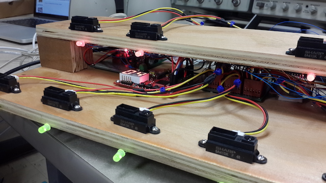
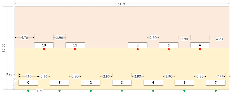
The board schematic shown displays the precise measurement of the board as well as where the keys are placed on the board. Keys are also assigned 0 to 11. This assignments is referenced by the LED numbering and the ADC_Ch signal. LEDs are placed beneath the keys, with red LEDs associated to the top keys and green LEDs associated to the bottom keys.
Power Circuit
SJ-One Board
First, the SJ-One Board is powered by the 5V and ground supplied by the power circuit.
VS1033
Analog to Digital Converter Circuit
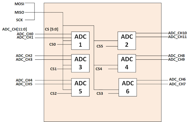
As seen, the MOSI, MISO, and CLK connections from the SJ-One Board connect to all of the analog to digital converter's Din, Dout, and CLK pins, respectively. 6 GPIO pins from the SJ-One Board are tied to each of the 6 CS pins of the analog to digital converters. VDD is connected to a 3.3 V source, while VREF is connected to ground for each ADC. Finally, the channels of the ADC are connected to the VO of the short IR sensors.
LED Driver
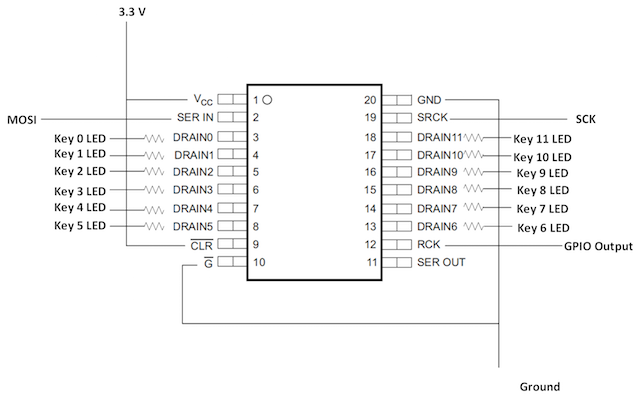
As seen, Drain0 to Drain11 are connected to 150 Ohm resistors, which in turn, are connected to their corresponding numbered key LED cathodes. All LEDs have their anode connected to a 5 V source. LEDs 0, 1, 2, 3, 4, 5, and 7 have its green cathode connect to 150 Ohm resistors and then to ground in order to illuminate green color all the time. Likewise, LEDs 10, 11, 8, 9, and 6 have their cathodes connected to 150 Ohm resistors and then to ground in order to illuminate red color at all times. Drains 0, 1, 2, 3, 4, 5, and 7 are connected to 150 Ohm resistors and then to their corresponding LEDs' red cathode. Drains 10, 11, 8, 9, and 6 are connected to 150 Ohm resistors and then to their corresponding LEDs' green cathode. The GND and G pins are connected to ground, while the VCC and CLR pins are connected to 3.3 V source. The MOSI, CLK, and GPIO output pins from the SJ-One board are connected to the SER IN, SCK, and RCK pins of the LED driver.
Hardware Interface
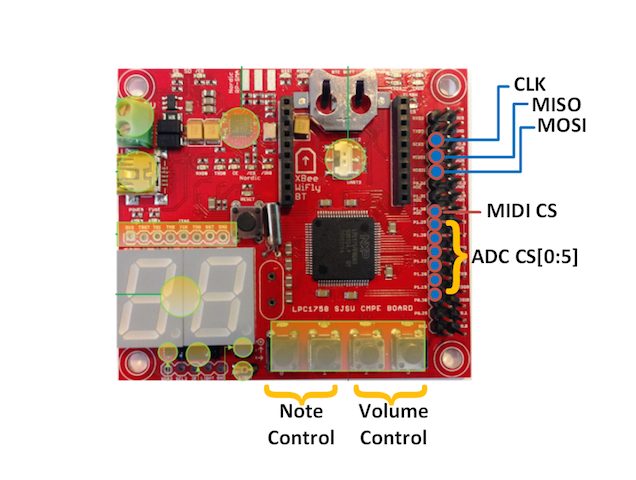
SPI was used used to communicate with the ADC devices, the MIDI decoder, and the LED driver. Meanwhile, GPIO was used as control signals, such as chip select and output enable, for the MIDI decoder and the LED driver. In the software, the following SPI and GPIO driver were used to communicate to the IO devices.
SPI driver:
   namespace My_spi {
       void init_ssp1_spi( void );                   // Using SCK1, MISO1, MOSI1 (P0.7, P0.8, P0.9)
       void init_cs( uint8_t port, uint8_t pin );
       char spi_exchange_byte ( char byte );
       void cs_select( uint8_t port, uint8_t pin );
       void cs_deselect( uint8_t port, uint8_t pin );
   }
For the My_spi driver, the init_ssp1_spi() function initializes LPC1758 SSP controller to function as an SPI controller with the following setting: MSB first, 8-bit data frame, and 500 KHz clock while other settings remained default. The init_cs(port, pin) function initializes a given IO pin to function as a GPIO output used for chip select. cs_select(port, pin) and cs_deselect(port, pin) functions are used to activate and deactivate a given IO pin respectively. Lastly, spi_exchange_byte(byte) function clocks 8-bits to and from a SPI slave device; cs_select(port, pin) and cs_deselect(port, pin) should be called before and after the call of the SPI exchange function(s) to target a specific SPI slave device. Exception: The LED driver is a shift register and does not use chip select. Instead, a GPIO output is used to signal the shift register to update its output (LEDs).
GPIO driver:
   namespace My_gpio {
       void set_gpio_mode( uint8_t port, uint8_t pin, bool mode );
       void digital_write( uint8_t port, uint8_t pin, bool state );
       bool digital_read( uint8_t port, uint8_t pin );                     // Assuming active high input
   }
For the My_gpio driver, the set_gpio_mode(port, pin, mode) function initializes a given IO port to function as a specific GPIO mode (mode can be either input or output). The digital_write(port, pin, state) function sets a given GPIO pin to a given voltage level or state (voltage level can either be high or low). The digital_read(port, pin) function reads the voltage level of a given pin and returns a Boolean value (returns true if high and false if low).
In this section, you can describe how your hardware communicates, such as which BUSes used. You can discuss your driver implementation here, such that the Software Design section is isolated to talk about high level workings rather than inner working of your project.
Software Design
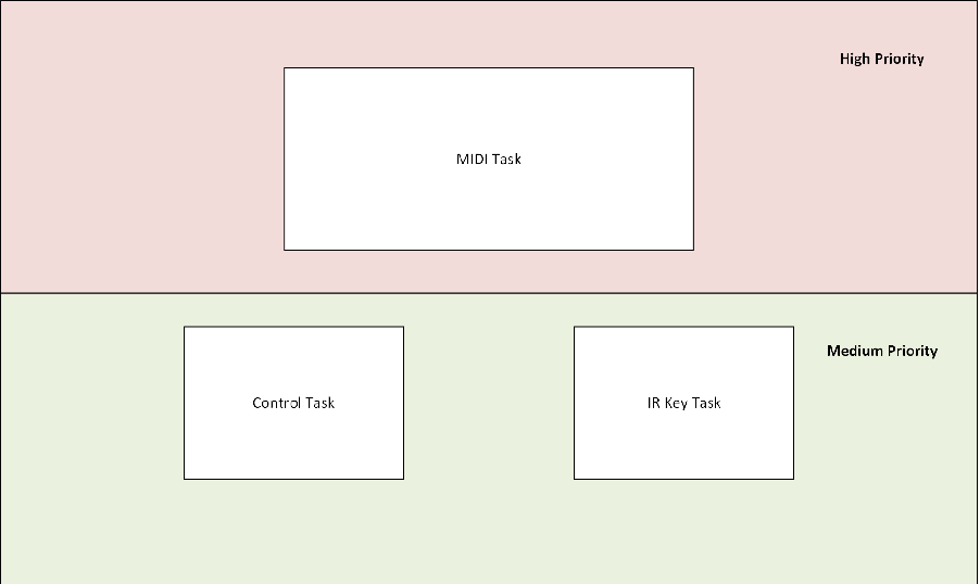
For the software design, there are three tasks: MIDI task (consumer), IR Key task (producer) and Control task (producer). During the idle state, the consumer remains in sleep and waits for a command from the producers. When an action takes place such as an activation of a key or a button, the consumer immediately wakes and executes the received command. Commands and messages are passed using FreeRTOS queues.
The MIDI task is responsible for playing notes at a certain pitch and volume. The task also provides feedback of the current pitch (octave) and volume using the SJ-One Board’s 7 segment display and on-board LEDs.
The IR Key task is responsible for sampling the IR sensors by reading the values from the ADC. If a key is sampled as active, then the key’s LED turns on, the key’s note and the play note command are sent to the MIDI task. The opposite occurs when a key is deactivated when previously in the active state.
The Control task is responsible for reading user input to increment/decrement pitch or volume by sampling the SJ-One Board’s on-board push button. When an input is active, the appropriate command gets sent to the MIDI task.
Implementation
MIDI Task Algorithm
1. Sleep and wait for a command.
2. If the play note command is received, then send the MIDI standard message via SPI to the MIDI decoder to play each note in the Note Queue.
3. If the increment/decrement volume command is received, then send the MIDI standard message via SPI to the MIDI decoder to increment/decrement the volume of the MIDI decoder.
4. If the increment/decrement pitch command is received, then offset base note by one range.
IR Key Sampling and Activation Algorithm
1. Using SPI, read 12 ADC channels (6 ADC, 2 channels each) to obtain the values of all 12 IR sensors.
2. Compare each value of the 12 IR sensors against valid margin levels.
3. If a key meets the valid active margin level, the note of the key is sent to the MIDI task Note’s Queue to be played.
4. For keys previously in the active state, if its value meets the valid inactive margin level, then the note of the key is sent to the MIDI task Note’s Queue to be turned off.
5. After all 12 values are checked, if any note had been sent to the MIDI task’s Note Queue, then update the key’s LED based on its new state.
6. Then, after all 12 values are checked AND if any note had been sent to the MIDI task’s Note Queue, send the command Play Note to the MIDI task’s Command Queue.
Control Task User Input Sampling and Activation Algorithm
1. Read the state of the SJ-One Board’s on-board push button.
2. If the increment pitch button is sampled active, then send the increment pitch command to the MIDI task; similarly, if the decrement pitch button is sampled active, then send the decrement pitch command to the MIDI task.
3. If the increment volume button is sampled active, then send the increment volume command to the MIDI task; similarly, if the decrement volume button is sampled active, then send the decrement volume command to the MIDI task.
Testing & Technical Challenges
Describe the challenges of your project. What advise would you give yourself or someone else if your project can be started from scratch again? Make a smooth transition to testing section and described what it took to test your project.
Include sub-sections that list out a problem and solution, such as:
LED driver soldering
At first, the LED driver had difficulty implementing. The problem that occurred was that the soldering of the LED driver to the TSSOP to DIP20 adapter may have created a short along the way. After fixing the soldering, the data was able to be sent to the LED driver as expected.
ADC chip select
A problem occurred when implementing the analog to digital convertors. When testing one ADC, the rest of the ADCs' chip selects were left floating. This led to bus contention. The problem was fixed by making all other un-used CS pins from the other ADCs high (not active), while the CS being used was low (active).
Conclusion
Conclude your project here. You can recap your testing and problems. You should address the "so what" part here to indicate what you ultimately learnt from this project. How has this project increased your knowledge?
Project Video
Project Source Code
References
Acknowledgement
Special acknowledgement to Preetpal Kang for suggesting IR sensors instead of motion sensors.
References Used
Short IR data sheet Media: CMPE146_F15_ElectricPiano_shortIR.pdf
Analog to digital converter datasheet Media: CMPE146_F15_ElectricPiano_ADC.pdf
LED driver data sheet Media:CMPE146_F15_ElectricPiano_LEDdriver.pdf
Appendix
You can list the references you used.
