F14: Team4-Self Driving Car - AUG
Contents
- 1 Introduction
- 2 Startup
- 3 Highlights
- 4 Team Members & Responsibilities
- 5 Parts List & Cost
- 6 CAN Architecture
- 7 Design & Implementation
- 8 Power Circuit
- 9 Sensor Controller
- 10 Motor Controller
- 11 I/O Controller
- 12 Communication Bridge + Android Controller
- 13 Geographical Controller
- 14 Master Controller
- 15 Schedule
- 16 Future Enhancement
- 17 Conclusion
- 18 Project Video
- 19 Project Source Code
- 20 References
Introduction
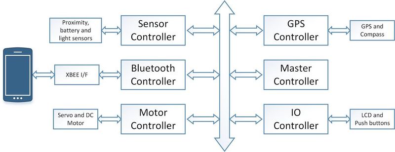
This project is aimed at developing a 1/10 RC car with a self-driving capability based on controller interaction over the CAN (Controller Area Network) bus. With the advent of driverless cars, we felt the need to develop a scaled-down version that can maneuver itself through co-ordinates fed by Google maps and correct its course when it sees an obstacle. To achieve this objective, we plan to integrate 6 controllers dedicated to specific roles that can pass messages over a common CAN communication bus. In addition, the prototype would involve an Android mobile application for data monitoring and controlling purpose to keep a track of the car remotely and feed it the required checkpoints to reach its destination. The car would comprise of three modes of operation namely; home, map and free run. In the home mode, the car would be guided to its home destination (which is preset to Boccardo Business center) from its current location. In the map mode, the user can feed in the desired destination through the google maps interface which the car would follow based on the co-ordinates and heading provided by its GPS and compass respectively. The free run mode will convert the mobile phone into a remote device capable of controlling the speed and direction of the car based on the accelerometer and gyroscope enabled on the device. In this way, the user can take control of the car at any given time. Below is the high-level block diagram of the entire system.
Startup
The following series of events would take place when the car is powered on:
- The GPS would wait for a satellite fix of at least 3 satellites, which would relay the information to the Android device through its controller over the CAN bus.
- If the user selects the Map mode, he would be required to enter the co-ordinates of the destination visually by dropping a marker on the map.
- The app would compute the checkpoints and distance and feed the information to the on-board communication controller.
- The first checkpoint is sent to the GPS and master controller, which would co-ordinate the events for the motor and sensor controllers.
- Any obstacle detected by the ultrasonic sensors would override the current path and try to avoid the obstacle.
- The master controller would compute the course correction and reconfigure the required controllers once the car has passed the obstacle.
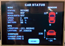
- The IO controller is responsible for monitoring the data on the CAN bus and displaying the information on the mounted LCD panel. The light and battery sensors are also connected to the IO controller, which automatically turn on the headlights and monitor the battery health respectively.
- Start/Stop triggers can be given to the car remotely using the mobile application as well as from the on-board LCD.
- Once the car reaches the first checkpoint, it will request for the second one from the communication controller and pass it over to the master. In this way, the process continues till the car reaches the destination.
- Home mode operates in a similar way but with a fixed destination and the free run mode is pretty much self-explanatory
Highlights
- Self-Navigation with Obstacle avoidance on all sides on the car.
- Google maps interface for location monitoring and destination setting along with checkpoint computation.
- Three modes of operation – Home, Map and Free run.
- Three choices of speed – Slow (8 mph), Normal (10 mph) and Turbo (12 mph).
- Automatic checkpoint detection and request for checkpoint system.
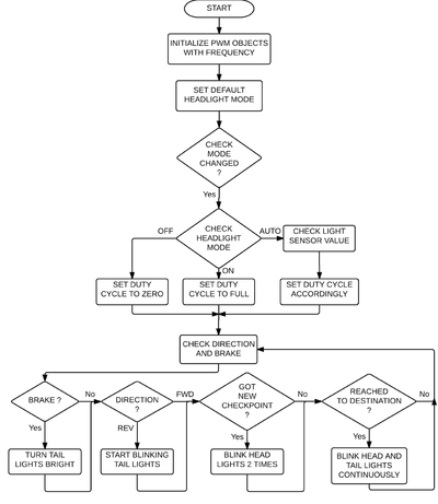
- Headlights using lights sensors and brake lights on the tail.
- Battery health monitoring.
- Visual picturization of sensor data relative the car on the android application.
- Speed gauge and compass needle for easier visualization on the application.
- Kill switch for instant power off.
- Free run mode for remotely controlling the car.
Team Members & Responsibilities
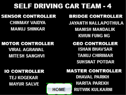
- Sensor Controller:
- Motor Controller
- I/O Unit:
- Communication Bridge + Android:
- Geographical Controller:
- Master Controller:
Parts List & Cost
| S.R. | Description | Manufacturer | Part Number | Qty | Total Cost |
|---|---|---|---|---|---|
| 1 | SJOne Board | - | - | 6 | $480.00 |
| 2 | RC Car | Traxxas | - | 1 | $240.00 |
| 3 | Ultrasonic Sensor | Parallax | 28015 | 3 | $69.00 |
| 4 | ADC Sensor | Maxbotix | MB1000 | 1 | $29.00 |
| 5 | LDR | - | - | 1 | $1.00 |
| 6 | Battery Health Monitoring Resistors | - | - | 2 | $2.00 |
| 7 | IR Sensor (Used as Speed Encoder) | - | - | 1 | $15.00 |
| 8 | GLCD with Touchscreen | 4D Systems | uLCD-32PTU | 1 | $106.00 |
| 9 | Tact Switches | - | - | 4 | $2.00 |
| 10 | LEDs with Holders | - | - | 4 | $2.00 |
| 11 | XBee Module | Digi | XBee Series1 | 2 | $40.00 |
| 12 | Bluetooth Module | Microchip | RN42XVP-I/RM | 1 | $20.00 |
| 13 | GPS Module | Sparkfun | GPS-11058 | 1 | $49.95 |
| 14 | Compass Module | Adafruit | HMC5883L | 1 | $9.95 |
| 15 | CAN Transceiver (Free Samples) | Microchip | MCP2551 | 6 | $0.00 |
| 16 | Linear Voltage Regulator (Free Sample) | LT | LT1083-5 | 1 | $0.00 |
| 17 | Miscellaneous | - | - | - | $20.00 |
| Total (Excluding Shipping and Taxes | $1085.90 |
CAN Architecture
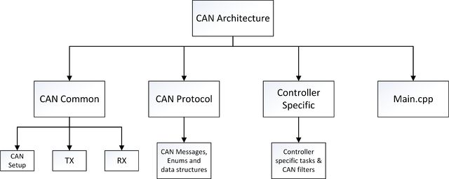
An architecture/framework was implemented to establish effective communication between all modules over the CAN bus. Architecture includes common enums, functions, and data structures used by all the modules.The CAN architecture consists of the following files.
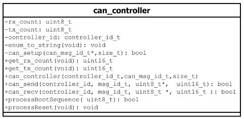
can_common.hpp/can_common.cpp – Declares and defines class can_controller
CAN Send/CAN Receive function: The CAN bus has the limitation of transmitting eight bytes of data per message frame. In order to overcome this limitation, C++ wrapper functions are included in the CAN architecture.
The can_send() wrapper function takes in destination controller ID, data, message ID and length of data i.e. number of bytes to be sent as the arguments. If the length is greater than eight bytes, the data is divided into packets of 8 bytes each where the zeroth byte indicates the total length the of packet. The data packet consists of seven bytes of actual data and one byte of length information.
The can_recv() wrapper has source controller ID, data, message ID and length of data as arguments. In the receiving function the last byte is checked for the length of the actual data packet. If the length is greater thaneight then the wrapper function performs receive till all the data bytes for that particular message frame are received.
Thus the data bytes are marshalled at the transmitting end and de-marshalled on the receiving end. Transmit count and receive count are also incremented for every transmit and receive performed per module.
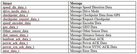
can_protocol.hpp - Includes all the enums for CAN messages, controller ID’s and Errors. The CAN message frame is made up of CAN message ID and data or information. For each message ID, data is sent over the CAN bus using a specific struct.
As shown in the example, the struct dist_sensor_t is used to send sensor data to other controller. Likewise, data structs for all message ID’s are created.
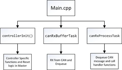
main.cpp – This is the entry point for all the modules. Each of the module’s main.cpp file consists of a controller_init function and two tasks-canRxBufferTask and canRxProcessTask.
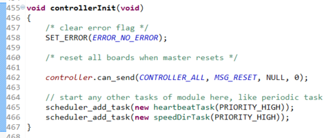
The controller_init function is defined in each modules controller_xxxx.cpp file (where xxxx is the respective module). This function in Master module includes sending reset command and adding Master controller specific tasks. For all other modules this function consists of adding controller specific tasks.
Example:
CAN Receive Buffer:
The canRxBufferTask is the receiving task defined in each modules controller_xxxx.cpp file. This is a dedicated task for receiving all the messages. All the messages received by this task in each module are collected in a FIFO queue.The only message not queued in the receive queue by the canRxBufferTaskis the Reset message since this message needs to be acted upon as soon as it is received.
CAN Receive Processing Task:
The canRxProcessTask is the receiving task defined in each modules controller_xxxx.cpp file. This task dequeues messages from the receive queue, decodes them and calls message specific handlers. Basically, it is a producer-consumer implementation.
Two separate tasks are created for receiving and processing the messages to ensure that no messages are missed and the messages are queued as soon as they are received. If there is only one task which both receives and processes the messages, it is possible that when the task is processing a message a new message might come in. Since there is no function to catch this message, it will get dropped. Hence, we have two tasks, so that one task will receive the message and queue it while the other will dequeue and process.
Power-Up Boot Sequence & Reset
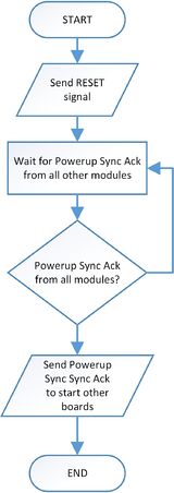
It is very important for all the modules to have sync amongst them.The idea is that all the modules should power up and be ready to start the sending and receiving of messages together. This is to ensure that no messages are missed by any module. No module will start sending messages on the CAN bus until all the modules are up and are ready.
The power-up boot sequence includes three-way hand shaking signals between Master and other modules. On power up Master sends reset signal to all modules. After resetting, the master sends a POWER_SYN message to all modules every one second until it receives POWER_SYNC_ACK from all modules. Master module maintains a register logging the POWER_SYNC_ACK signal of each module. After receiving this signal from all the modules the Master module sends POWER_ACK signal to all modules. After the reception of this message, all modules canstart their controller specific periodic tasks.
Whenever the Master resets all the other modules reset too and this power-up boot sequence is executed. This ensures that all modules are up and in sync. Also this helps in having a centralized reset mechanism.
HeartBeat: The Heartbeat message is sent periodically by master to all other modules. The purpose of the message is to check the health of all the modules. An acknowledgement message HEARTBEAT_ACK is sent in response to this message by all modules.If master does not receive an acknowledgement from any one of the module thrice in a row it sends a reset command to all other modules. The idea behind implementing this logic is to ensure all the modules are up and working. If any one of the module fails the master should reset everything.
Design & Implementation
CAN 11-bit ID Format
| MSG | DST | SRC |
|---|---|---|
| 5 bits (11-6) | 3 bits (5-3) | 3 bits (2-0) |
Controller ID Table
| Controller ID | Controller Type |
|---|---|
| 000 | All Controller |
| 001 | Motor Controller |
| 010 | Master Controller |
| 011 | Sensor Controller |
| 100 | GEO Controller |
| 110 | Communication Bridge + Android Controller |
| 111 | I/O Controller |
Controller Communication Table
| S.R. | Message Number | Destination | Message Name (MSG_FUNCTION) | Data Layout of Data Sent over CAN (byte[0] = total number of data bytes) |
|---|---|---|---|---|
| 1 | 0x042 | All | RESET |
NO DATA |
| 2 | 0x082 | All | POWERUP_SYN |
NO DATA |
| 3 | 0x102 | All | POWERUP_ACK |
Msg1 : byte[1] : (uint8_t) version Msg1 : byte[2-3] : (uint16_t) year Msg1 : byte[4] : (uint8_t) month Msg1 : byte[5] : (uint8_t) date Msg1 : byte[6] : (uint8_t) dayofweek Msg1 : byte[7] : (uint8_t) hour Msg2 : byte[1] : (uint8_t) minute Msg2 : byte[2] : (uint8_t) second |
| 4 | 0x142 | All | HEARTBEAT |
Msg1 : byte[1-2] : (uint16_t) rx_count Msg1 : byte[3-4] : (uint16_t) rx_bytes Msg1 : byte[5-6] : (uint16_t) tx_count Msg1 : byte[7] : (uint16_t) tx_bytes Msg2 : byte[1] : (uint16_t) tx_bytes |
| 5 | 0x3CA | Motor | SPEED_DIR_COMMAND |
Msg1 : byte[1] : (uint8_t) speed Msg1 : byte[2] : (uint8_t) direction Msg1 : byte[3] : (uint8_t) brake |
| S.R. | Message Number | Destination | Message Name (MSG_FUNCTION) | Data Layout of Data Sent over CAN (byte[0] = total number of data bytes) |
|---|---|---|---|---|
| 1 | 0x0D1 | Master | POWERUP_SYN_ACK |
Msg1 : byte[1] : (uint8_t) version |
| 2 | 0x191 | Master | HEARTBEAT_ACK |
Msg1 : byte[1-2] : (uint16_t) rx_count Msg1 : byte[3-4] : (uint16_t) rx_bytes Msg1 : byte[5-6] : (uint16_t) tx_count Msg1 : byte[7] : (uint16_t) tx_bytes Msg2 : byte[1] : (uint16_t) tx_bytes |
| 3 | 0x341 | Master, I/O and Communication Bridge | SPEED_ENCODER_DATA |
Msg1 : byte[1] : (uint8_t) speed Msg1 : byte[2] : (uint8_t) dir Msg1 : byte[3] : (uint8_t) brake |
| S.R. | Message Number | Destination | Message Name (MSG_FUNCTION) | Data Layout of Data Sent over CAN (byte[0] = total number of data bytes) |
|---|---|---|---|---|
| 1 | 0x0D4 | Master | POWERUP_SYN_ACK |
Msg1 : byte[1] : (uint8_t) version |
| 2 | 0x194 | Master | HEARTBEAT_ACK |
Msg1 : byte[1-2] : (uint16_t) rx_count Msg1 : byte[3-4] : (uint16_t) rx_bytes Msg1 : byte[5-6] : (uint16_t) tx_count Msg1 : byte[7] : (uint16_t) tx_bytes Msg2 : byte[1] : (uint16_t) tx_bytes |
| 3 | 0x384 | Master, I/O and Communication | GEO_HEADING_DATA |
Msg1 : byte[1] : (uint8_t) current_angle Msg1 : byte[2] : (uint8_t) desired_angle Msg1 : byte[3] : (uint8_t) destination_reached Msg1 : byte[4] : (uint8_t) is_valid |
| 4 | 0x484 | I/O and Communication Bridge | GEO_LOCATION_DATA |
Msg1 : byte[1-4] : (float) latitude Msg1 : byte[5-7] : (float) longitude Msg2 : byte[1] : (float) longitude Msg2 : byte[2-3] : (uint16_t) dist_to_final_destination Msg2 : byte[4-5] : (uint16_t) dist_to_next_checkpoint Msg2 : byte[6] : (uint8_t) is_valid |
| 5 | 0x2AC | Communication Bridge | CHECKPOINT_REQUEST |
Msg1 : byte[1] : (uint8_t) checkpoint_num |
| S.R. | Message Number | Destination | Message Name (MSG_FUNCTION) | Data Layout of Data Sent over CAN (byte[0] = total number of data bytes) |
|---|---|---|---|---|
| 1 | 0x0D5 | Master | POWERUP_SYN_ACK |
Msg1 : byte[1] : (uint8_t) version |
| 2 | 0x195 | Master | HEARTBEAT_ACK |
Msg1 : byte[1-2] : (uint16_t) rx_count Msg1 : byte[3-4] : (uint16_t) rx_bytes Msg1 : byte[5-6] : (uint16_t) tx_count Msg1 : byte[7] : (uint16_t) tx_bytes Msg2 : byte[1] : (uint16_t) tx_bytes |
| 3 | 0x1D5 | Master and I/O | CAR_PAUSE |
NO DATA |
| 4 | 0x215 | Master and I/O | CAR_RESUME |
NO DATA |
| 5 | 0x425 | Geographical | CHECKPOINT_DATA |
Msg1 : byte[1-4] : (float) latitude Msg1 : byte[5-7] : (float) longitude Msg2 : byte[1] : (float) longitude Msg2 : byte[2-3] : (uint16_t) total_distance Msg2 : byte[4] : (uint8_t) checkpoint_num Msg2 : byte[5] : (uint8_t) is_new_route Msg2 : byte[6] : (uint8_t) is_final_checkpoint |
| 6 | 0x2C5 | Master, I/O, Communication Bridge and Motor | DRIVE_MODE |
Msg1 : byte[1] : (uint8_t) mode |
| 7 | 0x255 | Master | FREE_RUN_DIR |
Msg1 : byte[1] : (uint8_t) speed Msg1 : byte[2] : (uint8_t) turn Msg1 : byte[3] : (uint8_t) direction |
| S.R. | Message Number | Destination | Message Name (MSG_FUNCTION) | Data Layout of Data Sent over CAN (byte[0] = total number of data bytes) |
|---|---|---|---|---|
| 1 | 0x0D3 | Master | POWERUP_SYN_ACK |
Msg1 : byte[1] : (uint8_t) version |
| 2 | 0x193 | Master | HEARTBEAT_ACK |
Msg1 : byte[1-2] : (uint16_t) rx_count Msg1 : byte[3-4] : (uint16_t) rx_bytes Msg1 : byte[5-6] : (uint16_t) tx_count Msg1 : byte[7] : (uint16_t) tx_bytes Msg2 : byte[1] : (uint16_t) tx_bytes |
| 3 | 0x303 | Master, I/O and Communication Bridge | DIST_SENSOR_DATA |
Msg1 : byte[1] : (uint8t) left Msg1 : byte[2] : (uint8t) middle Msg1 : byte[3] : (uint8t) right Msg1 : byte[4] : (uint8t) back |
| 4 | 0x443 | I/O and Communication Bridge | OTHER_SENSOR_DATA |
Msg1 : byte[1] : (uint8t) battery Msg1 : byte[2] : (uint8t) light |
| S.R. | Message Number | Destination | Message Name (MSG_FUNCTION) | Data Layout of Data Sent over CAN (byte[0] = total number of data bytes) |
|---|---|---|---|---|
| 1 | 0x056 | Master | RESET |
NO DATA |
| 2 | 0x0D6 | Master | POWERUP_SYN_ACK |
Msg1 : byte[1] : (uint8_t) version |
| 3 | 0x196 | Master | HEARTBEAT_ACK |
Msg1 : byte[1-2] : (uint16_t) rx_count Msg1 : byte[3-4] : (uint16_t) rx_bytes Msg1 : byte[5-6] : (uint16_t) tx_count Msg1 : byte[7] : (uint16_t) tx_bytes Msg2 : byte[1] : (uint16_t) tx_bytes |
| 4 | 0x1D4 | Master and I/O | CAR_PAUSE |
NO DATA |
| 5 | 0x214 | Master and I/O | CAR_RESUME |
NO DATA |
| 6 | 0x2C4 | Master, I/O and Motor | DRIVE_MODE |
Msg1 : byte[1] : (uint8_t) mode |
Power Circuit
|
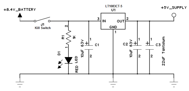
We used 8.4V, 3AH battery for car operation. As the most of the circuit components in the system such as SJOne board, ultrasonic sensors, CAN transceiver need stable DC +5V power supply, we built power supply circuit. We calculated the current consumption required for all system which came approximately 1.5 Ampere which is quite high. So we opted out the normal linear voltage regulator LM7805 which provides maximum 1 Ampere current output. We searched on internet and then selected LT1083-5 from Linear Technology which provides +5V with max 7.5 Ampere output current. The circuit diagram for the power supply is as shown in figure above. Two filtering capacitors are added to get proper output. The kill switch J1 is connected in series with battery positive to turn on/off the car supply. The red LED D1 will indicate whether car’s power is on or off. |
Sensor Controller
The sensor board continuously computes various sensor values and sends these values to other controllers. The master controller uses these values to take decisions. The I/O controller displays some of the sensor values. The sensors which are interfaced to the board are:
- Distance sensors
- Light sensor
- Battery sensor
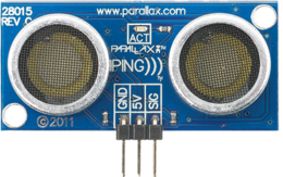
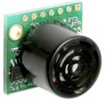
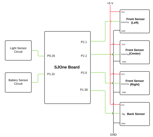
Two type of ultrasonic distance sensors are used. Three PING ultrasonic distance sensors are at the front (left,center and right) and one LV-MaxSonar-EZ0 ultrasonic sensor at the back. The values of these sensors are continuously sent to the master. Based on these values the master controller makes the computations to avoid obstacles. A light dependent resistor(LDR) is used for sensing the ambient light. The values are continuously sent to the I/O controller. According to these values the I/O controller changes the intensity of headlights.
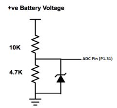
A voltage divider circuit is used to get the battery voltage. The percentage of battery remaining is computed and sent to the I/O controller. The I/O controller displays the battery percentage on the LCD. The onboard 3-axis accelerometer is used to obtain the orientation characteristics of the car. The values obtained for X-axis, Y-axis and Z-axis are sent to the I/O controller. The I/O controller displays these values on the LCD. Depending upon these values, we determine the inclination of the terrain on which the car is running.
Distance Sensor
The obstacle detection is done using 2 type of sensors which are PING ultrasonic distance sensor (Three are used in the front) and LV-MaxSonar-EZ0 ultrasonic sensor which is used at the back.
PING Ultrasonic Distance Sensor:
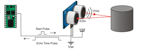
A single I/O pin is used to trigger an ultrasonic burst (well above human hearing) and then "listen" for the echo return pulse. The sensor measures the time required for the echo return, and returns this value to the microcontroller as a variable-width pulse via the same I/O pin.
Some key features of this sensor are:
Details:
|
Software Design
We need a trigger function and an echo function for the sensor in order to obtain the distance values. The trigger signal is given by keeping the gpio as High for 5 micro seconds and then making it low. Then we configure the same pin as input from the echo and then the function waits for data from the echo pulse. The data reception was queued so that the triggers from all of the sensors do not overlap and create errors in the distance values.


A callback function is used in order to obtain the duration of the echo pulse.Also, there has to be a delay of 750 microseconds between trigger and echo pulse according to the datasheet in order to obtain correct sensor values. Further, we obtain the distance using the formula Distance = (systime_center-750)/75.
LV-MaxSonar-EZ0 ultrasonic sensor uses an ADC interface for providing the sensor values.We configure the pin P1.30 as adc using the bit manipulation. Then we can read the current sensor values using adc0_get_reading function.

For the battery sensor and Light sensor, we use the circuits as shown in the figure. The reading from the circuit is directly taken to the adc pin and calibrated according the requirements.

|
Depending on the ambient light the table shows some of the ADC readings of the light sensor circuit. Since the ADC is 12 bit, so it can give a maximum value of 4096. The formula used for getting the light percentage from the ADC reading is |
Tablex: Light Sensor Readings |
|
Using a voltage divider circuit the battery is connected on an ADC pin. The battery voltage on the ADC pin is calculated using the formula |
Tablex: Battery Sensor Readings |
Challenges and Learnings
1. Limited ADC ports on SJOne Board:
All the sensors have to be a single board in order to have a good design. We should not use other board just to control one sensor. Initially we were planning to use LV-MaxSonar-EZ0 ultrasonic sensor for front as well as back. Light sensor and battery sensor also require ADC port. So overall we needed 6 ADC ports but there are only three ADC pins on the SJ One board. So, instead of using the ADC pins from other boards we changed out design and used three ultrasonic PING sensors in the front which do not require ADC pins.
2. Accuracy of Sensors:
The sensors are reading and sending values to the master at a very fast rate. We observed that sometimes the sensors will give a garbage value in between. We don’t want the master to take the decision on that single reading. So we used a cleaning algorithm that basically averages the values of some readings and send the averaged value to the master. In this way the error difference is reduced.
Motor Controller
Hardware Design
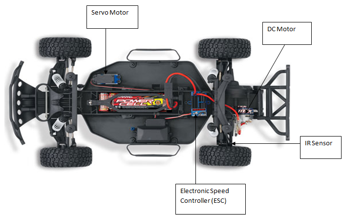
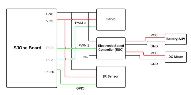
<p align="justify"> The main components of the motor controller hardware are DC motor, Servo motor, Electronic Speed Controller(ESC) and IR sensor. The external battery of 8.4V is used to power up the DC motor via ESC.
We use Pulse Width Modulation (PWM) signals used to control the DC motor and Servo motor. The PWM signal is given through the PWM pin P2.1 and P2.2 of the SJ-One board. The output of the IR sensor is taken at the GPIO pin P0.26. Voltage required to drive the servo motor is given through the 3.3V Vcc of the SJOne board. The ground of all the components is connected with the GND pin of SJOne board to form a common ground.
Electronic Speed Controller (ESC)
|
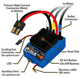
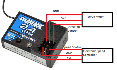
The RC car came with a pre-installed ESC (electronic speed controller), the Velineon VXL-3s which contains an inbuilt circuitry to control the movement and speed of the motors. This was the trickiest part as we had to debug the working of this circuitry and control the working of the motors with the help of PWM value given from the SJOne board. |
|
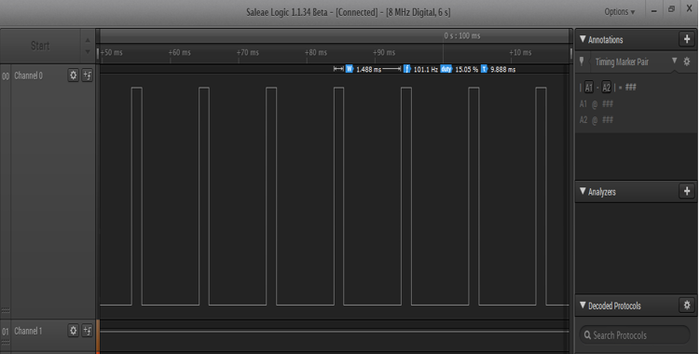
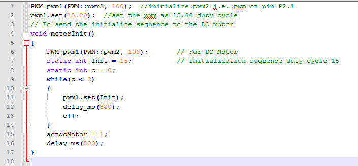
To debug the ESC we connect logic analyzer at GND pin and speed control pin. We do not move the speed trigger of the wireless remote and notice that the motor controller circuit is sending some initialize pulse of duty cycle 15.05% to initialize the ESC. |
|
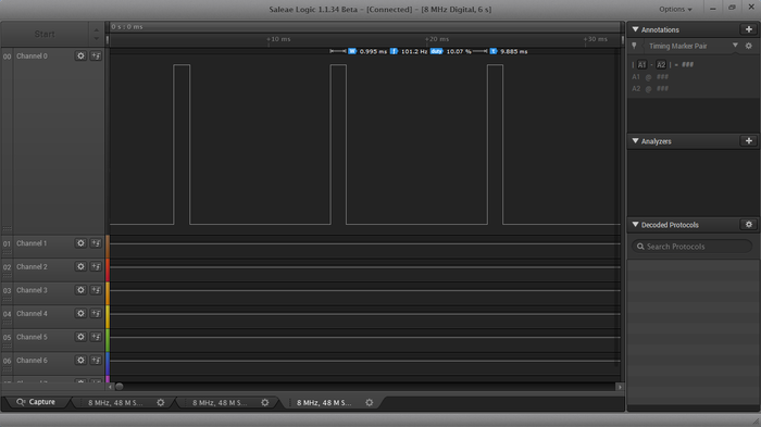
For maximum reverse speed the motor controller circuit is sending duty cycle of 10.07% to ESC. So the DC motor has the reverse duty cycle range from 15.05% – 10.07%, but due to the weight of the car for us the initial reverse duty cycle is 14.20%. |
|
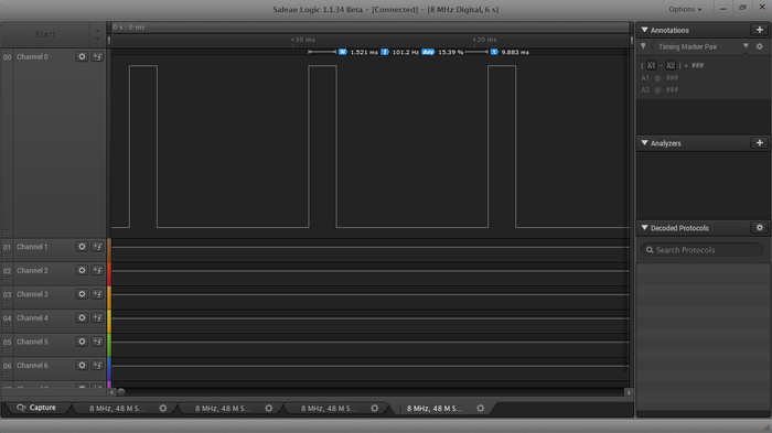
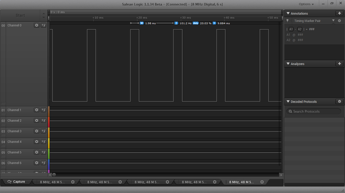
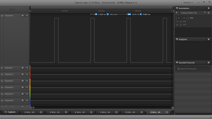
To determine the duty cycle range for the servo motor we connected the logic analyzer at GND and turn control pin of the servo motor. For straight the servo duty cycle we see on the logic analyzer is 15.39% |
|
For maximum full right of the servo motor, the motor controller circuit is sending duty cycle of 20.03% to ESC. So the servo motor has the straight to full right duty cycle range from 15.39% – 20.03%. |
|
For maximum full left of the servo motor, the motor controller circuit is sending duty cycle of 10.41% to ESC. So the servo motor has the straight to full left duty cycle range from 15.39% – 10.41%. |
DC Motor
|
Our car came installed with the Velineon 3500 Brushless motor. The motor needs 8.4V of power supply to work. This motor has the power to run the car at the maximum speed of the 35mph.
Tablex: DC Motor Duty Cycle v/s Speed |
|
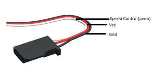
DC motor is controlled with the help of three wires coming out of the ESC. The wires are Vcc, Gnd and Speed control. The Vcc is not used as required voltage is directly given to motor through battery via ESC. The Gnd is connected with Gnd pin and Speed control is connected to the PWM pin of SJOne board.
Tablex: DC Motor Pin Connections For DC motor we are using pwm2 i.e. pin P2.1 of the SJOne board, the pwm function is the in-build function which requires two parameters, one is pwm that we are using and the second parameter is the frequency of the pwm. To set the duty cycle in-build set function is used in which we are passing the duty cycle at which we want DC motor to work. |
Servo Motor
|
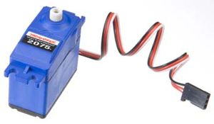
Our car came with waterproof digital servo motor (Traxxas part 2075). This motor works without ESC. We can directly control this motor by giving PWM signal from our SJOne board. The below table contains information about PWM (duty cycle) given to the motor and the corresponding turns taken by the car.
Tablex: Servo Motor Duty Cycle v/s Turn |
|
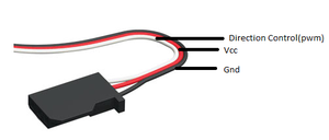
Servo motor is controlled with the help of three wires coming out of the servo motor. The wires are Vcc, Gnd and Direction control. The Vcc is connected to the 3.3v, Gnd is connected with Gnd pin and direction control is connected to the pwm pin of SJOne board.
Tablex: Servo Motor Pin Connections For Servo motor we are using pwm3 i.e. pin P2.2 of the SJOne board, the pwm function is the in-build function which requires two parameters, one is pwm that we are using and the second parameter is the frequency of the pwm. To set the duty cycle in-build set function is used in which we are passing the duty cycle at which we want servo motor to work. |
Speed Sensor
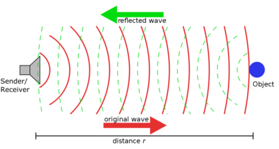
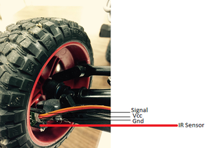
To calculate the speed of the car we interfaced an IR sensor on the inner back left wheel of the car. We have attached the IR sensor on the inner surface of the wheel which is reflective, so we attach a black rubber on the wheel which acts as a non-reflective object. The IR sensor code will count the number of times the transmitted wave is not received back. Based on the total count we determine the real time speed of the car.
Working of IR Sensor:
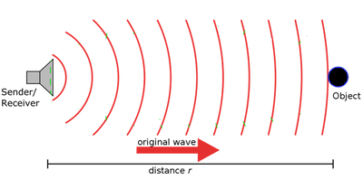
The IR sensor send the transmitted wave, if the object is reflective than the sensor will receive the reflected wave but if the object is non-reflective i.e. of black color than sensor will not receive the reflected wave as the non-reflective surface will absorb the transmitted wave.
|
For sensor the inner surface of the wheel is reflecting so we stick a black piece of rubber on it which will not get reflected. This will allow us to determine when wheel will complete one rotation.
Tablex: IR Sensor Pin Connections |
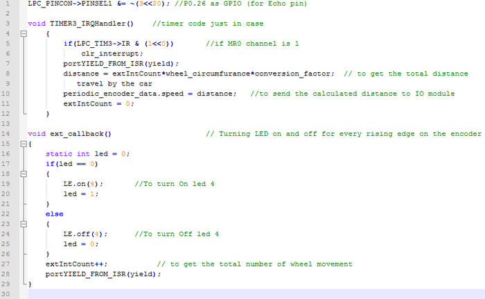
To send and receive signal from the IR sensor we have interfaced the signal pin of the IR sensor at the GPIO pin P0.26 of the SJOne board. The ext_callback() is used to get the number of count from the IR sensor. In-build hard timer TIME3_IRQHandler() is used to get the speed of the car using the total count from ext_callback() function, the circumference of the car which in our case is 35cm and the conversion factor of cm to mph.
I/O Controller
Introduction
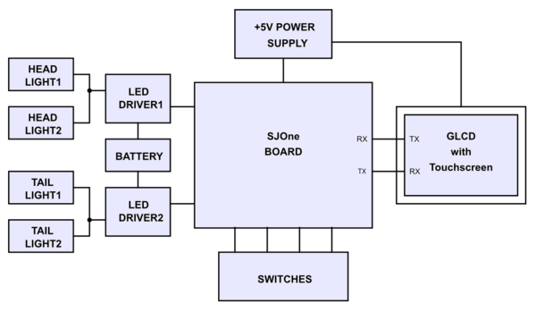
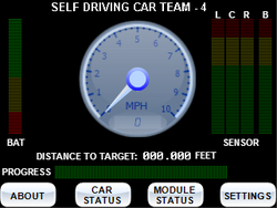
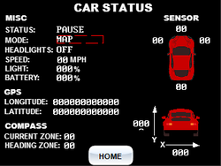
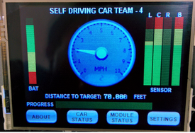
IO is the mode of interaction between user and car peripherals. It includes touch screen GLCD, headlights and switches. LCD reflects the car status while the touch screen and switches give a dynamic control to shift between various modes. The head and tail light is an easy and convenient way to know the state and transition of the car.
|
Objectives:
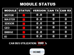
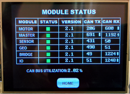
2. Display each controller’s status, number of messages transmitted, number of messages received on CAN bus and also CAN bus utilization. |
GLCD
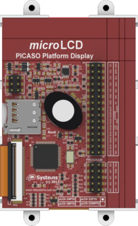
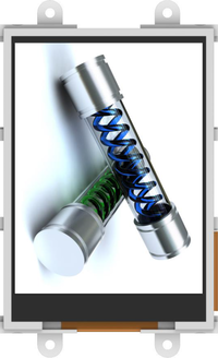
The touch screen GLCD uLCD32PTU was purchased from 4D Systems. The reason for selecting this LCD was its ready availability, low cost and ease of use. Moreover, some members from group had good experience using the product.
|
Features:
|
|
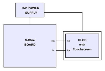
Description of Circuit Diagram and Connections:
|
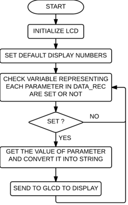
Software Implementation:
|
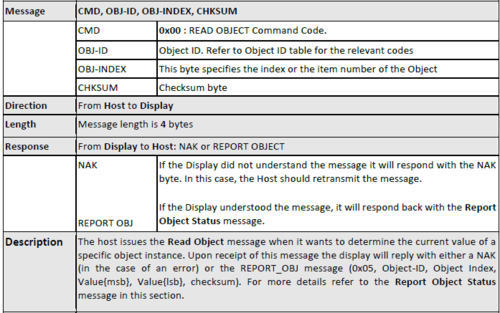
- CMD: This byte indicates the command code. Some commands will have more parameters than others. The table below outlines the available commands and their relevant parameters.
- PARAM: Parameter bytes (variable); a variable number of parameter bytes (between 1 to N) that contains information pertaining to the command. Refer to the command table below.
- CHKSUM: Checksum byte; this byte is calculated by taking each byte and XOR’ing all bytes in the message from (and including) the CMD byte to the last parameter byte. Then, the result is appended to the end to yield the checksum byte.
- Note: If the message is correct, XOR’ing all the bytes (including the checksum byte) will give a result of zero.
Transmission of Command Frame to GLCD:
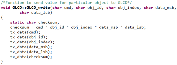
The following code snippet shows how to send any command to GLCD:
- The tx_data(char data_tx) function is made to transmit the byte from UART port of SJOne board.
- GLCD_write(char cmd, char obj_id, char obj_index, char data_msb, char data_lsb) function is made to send different data frames to GLCD.
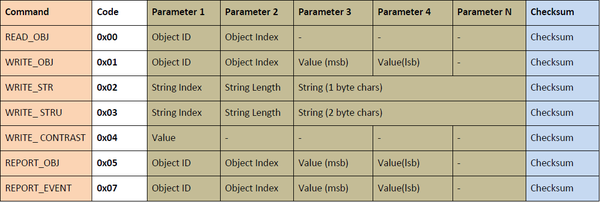
Different commands and number of parameters that need to be specified for each command is as shown in the table below. e.g. For displaying speed 2mph on the GLCD’s odometer the data frame we send to GLCD is 0x01 (WRITE_OBJ), 0x08 (OBJECT_ID), 0x00 (OBJECT_INDEX), 0x00 (Value_msb), 0x02 (Value_lsb), 0x0B (Checksum)
Reception of Command Frame from GLCD:
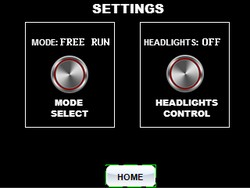
- On the ‘Settings’ screen we have provided two buttons for changing the mode. For this purpose we have set the handler to ‘Report event’ for both the buttons in ViSi Genie IDE. This enables the GLCD to form one message and send it to the UART port whenever the user presses any button on touch screen.
- The SJOne board’s UART is then configured as an interrupt based UART so that it triggers an interrupt whenever a message is received via the RXD pin of UART.
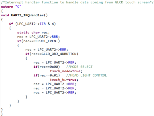
- This interrupt is handled by writing the ISR (Interrupt Service Routine) to read the byte received in buffer. The code snippet for this is as given below.
|
Head & Tail Light
We have used white LED for headlights and red LED as tail lights. The Tail and Head lights are low power consuming super bright LEDs.
Features:
- The head and tail lights each have a power rating of 3W.
- The head light is bright white with a current rating of 600 to 750mA and voltage rating of 3 to 3.5V.
- The tail lights are bright red in colour with a current rating of 700mA and voltage rating of 2 to 2.5V.
Description of Hardware:
- The LED used for headlights are very bright. The current flowing thought LED should be high so as to increase the brightness.
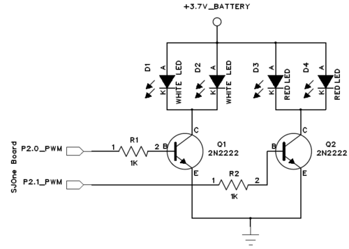
- The LED amplitude can be modified with varying PWM duty cycle. To facilitate this purpose we have used the PWM pins over normal GPIO pins. As any GPIO/PWM pin of microcontroller cannot supply more than 10mA current without damaging, we built LED driver circuit for headlights and taillights.
- Here transistor 2N2222 is selected to work as a switch as it is capable of managing high collector current.
- We have used two white LEDs for headlights and two red LEDs for tail lights as shown in the circuit diagram. All the cathode terminals are connected to the collector of transistor, while anode of LEDs are connected to an external Li-ion battery of 3.7V, 3AH.
- We have used a separate portable battery for the LEDs to avoid the main battery from draining quickly. This increases the life of the main battery.
Software Implementation:
|
Switches
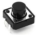
Four hardwired switches have been provided for car start/stop, GLCD On/Off, Home destination and reset ALL. The switches are very tactile and the bounce time is 5 ms which helps in de-bouncing up to a certain extent.
|
Features:
|
Description of Hardware:
- In the above circuit, the tactile switches are connected between VCC and 10K resistor.
- All switches are connected in active high configuration so that when switch is pressed, the port pins will be pulled to a logic ‘high’ else they are at logic ‘low’.
Software Implementation:
|
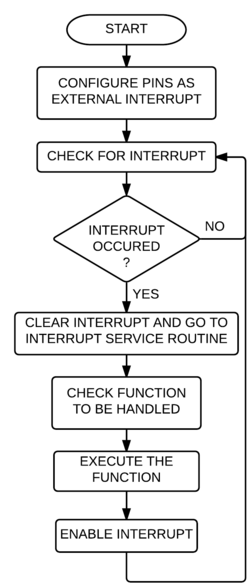
As the SJOne board is running on FreeRTOS, the normal switch detection procedure with 'if' condition is not efficient. For this purpose we have implemented the interrupt based model using external hardware interrupt pins.
|
Technical Challenges:
- The head and tail-lights drain large amount of current which made it necessary to use an extra battery.
- On-chip memory was not sufficient to hold the code for LCD. An external SD card was used which had to be removed whenever the code was to be tested. This is not the most convenient method.
Learning:
- Hands-on experience on LPC1768 and its various peripherals such as UART, PWM, Interrupt configurations.
- Got to use learn the ViSi Genie IDE for uLCD-32PTU. The IDE is extremely user friendly which provides built in objects and gives drag and drop facility.
Future Enhancement:
- On-chip memory for the LCD can be increased to store large amount of code.
Communication Bridge + Android Controller
Introduction
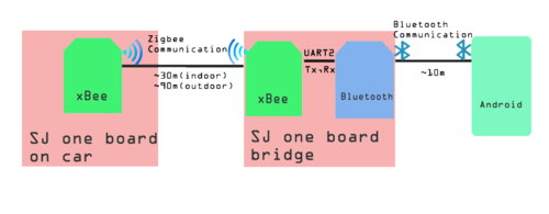
The communication bridge is a connection between Android application and other controllers on the RC car. The Android application is written in Java and there are xBee(ZigBee) chip sets along with Bluetooth as a bridge connection. The major functions of the bridge is
- Allow a user to see sensor values, car speed, etc.
- Allow a user to select a destination from Google Earth.
Modules
1. xBee Module:
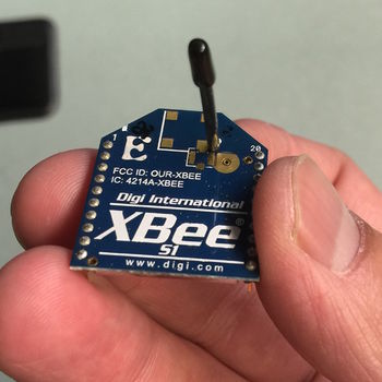
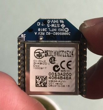
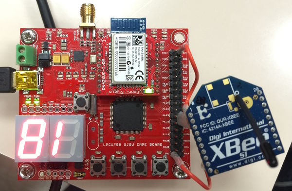
The following pictures shown the chip set of xBee which is using zigbee to communicate with each other:
|
Features:
|
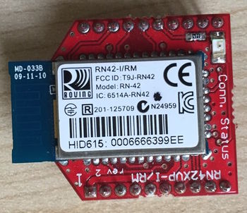
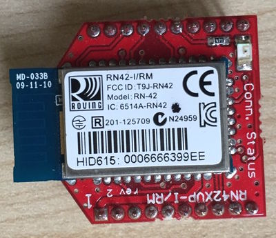
2. Bluetooth Module (RN-421):
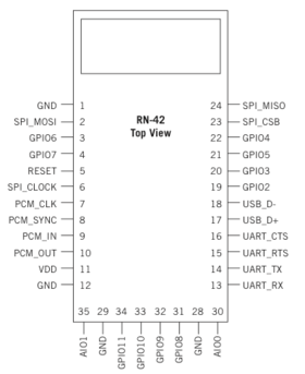
The following picture is the Bluetooth module RN-42I:
Features:
- Fully qualified Bluetooth version 2.1 module, support version 2.1+Enhanced Data Rate (EDR)
- Backwards compatible with Bluetooth version 2.0, 1.2 and 1.1.
- Low power (26uA sleep, 3mA connected, 30mA transmit)
- UART (SPP or HCL) and USB (HCI only) data connection interfaces.
- Sustained SPP data rates: 240 Kbps (slave), 300Kbps (master)
- HCI data rates: 1.5 Mbps sustained, 2.0Mbps burst in HCI mode
- Bluetooth SIG certified
- Castellated SMT pads for easy and reliable PCB mounting
- Certifications: FCC, ICS, CE
Interface
1. xBee:
Communication setup:
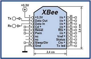
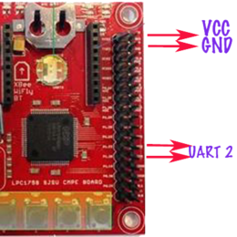
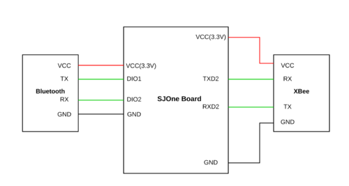
Since we are not connecting the xBee directly to our computer to work on the configuration and we have to connect it through using the SJ One board with UART communication pins. Thus, we have to initially set the baud rate at 115200. On xBee chip set, there are 20 pins including VCC and GND. In our design of the communication bridge, we just need four of them including VCC (Pin1), GND(Pin10), Data Out(Pin2), and Data In (Pin3). For xBee chip set connected with Bluetooth module, VCC is connected to SJ One board VCC out as well as GND. For Data out on xBee, it is connected UART 2 Rx(Pin49) and Data in connected to UART Tx(Pin50). For xBee chip set connected to car SJ One board, we can directly place it on xBee connect pins on SJ One board.
Pairing:
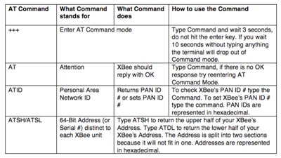
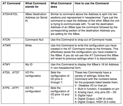
In order to let the xBee pair to communicate to each other, we have to set both xBee chip sets have the same PAN ID. The xBee has factory default setting that we just have to input default commands for viewing or changing the setting on chips. Some of major commands show as following:
Since we are using SJ One board to connect with the xBee chip sets, so we have decided to implement commands inside the FreeRTOS program. In the implementation, we have included the following logic to pair the xBee chip sets. Steps of pairing xBee chip set:
- Checking both xBee chip sets are working with “AT” command and it will return “OK” for working
- Checking and changing PAN ID on either one xBee to match with another and the PAN ID are usually 4 digits numbers. “ATID” is the command to check and change the ID
- Checking and changing the destination address for both xBee chip sets. The address of chip sets are printed on the bottom of the xBee.
2. Bridge between xBee and bluetooth:
Since xBee cannot communicate with regular android cell phone, we would need one device/module that common accepted for both configurations. Bluetooth is one of the best devices for this purpose. In order to create a platform for these two device (Bluetooth and xBee), SJ One board has been used as the medium to make communication bridge them. On the SJ One board, we have chosen UART 2 as communication connector among UART 2 or UART 3. There is no logic stored on the SJ One board but the initialization for the UART port. The logic for the communication for Bluetooth and xBee module is simple. The baud rate has to set to 115200 for both module Tx of Bluetooth has to connect with Tx of xBee while Rx of Bluetooth has to connect with Rx of xBee. Besides, both Vcc(3.3V) and Ground of Bluetooth module and xBee module are connected to the Vcc and ground on SJ One board respectively.
3. Bluetooth:
Bluetooth module is providing a connection for Android device and xBee. There is no initialization such as initializing Pan ID on xBee on the Bluetooth module but the Android device side. For the first time connection between Android device and the Bluetooth module, we need to pair them. In the Bluetooth device searching section (Setting -> Bluetooth) of the Android device, we can see the Bluetooth module name e.g.RNBT-99EE. In order to pair them, there is a default pass code (0000 or 1234) to enter from the Android device.
Android Application
The Android Application is connected to the car through the Bluetooth-xbee interface. The first point of contact for the application is the Bluetooth module for which a separate class was written which connects using sockets based on the UUID (Universally Unique Identifier) and pairing history of the device running the code.
This snippet would get the UUID for connecting to a Bluetooth serial board that is a well-known UUID. If we were using an Android peer, we would have created our own unique UUID.
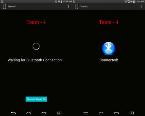
Just like socket programming, we create output and input streams for the data and close the sockets once the connection has ended. The simplest way to open a Bluetooth socket is by opening a BluetoothSocket for communication with the remote device, using createRfcommSocketToServiceRecord (UUID) as shown above. The application has been configured such that the user cannot go past the connectivity page until the Bluetooth of the android has connected to the module. This ensures that there’s no false sending/receiving of data and does not lead to the user to believe the data has been sent without actually connecting. The connectivity page is shown below:
The android application has been divided into 3 views (rather Activities) to visualize the following:
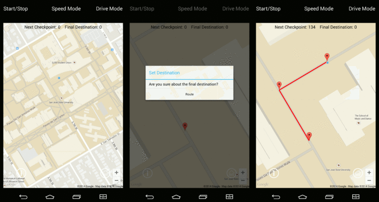
1. A Google maps view show the route and current location
In this Activity, the user can drop a pin at any point and request for a route from the Google maps API which would send back a response in the JSON format. Upon parsing, the checkpoints are extracted and plotted on the map fragment. Upon completion, all checkpoints are sent to the communication module in the following format:
g37.34252,-121.12234,37.636423,-121.76543,350$
‘g’ stands for geo data that the lpc module recognizes and stores the lat-long values that follow. The last value in the string is the total distance from the source to the destination. The ‘$’ termination is used as a common two-way message termination character. Even when any messages on the CAN bus are sent to the android application, they are sent with a ‘$’ termination. On top of each view of the application, the user can select the drive mode, start/stop the car and select the drive speed. This brings about ease of use and uniformity to the application. The current location is plotted and shown with a blue dot which changes dynamically based on the location fed by the GPS controller on the bus. All locations and checkpoints are displayed using the Marker object of the Android API.
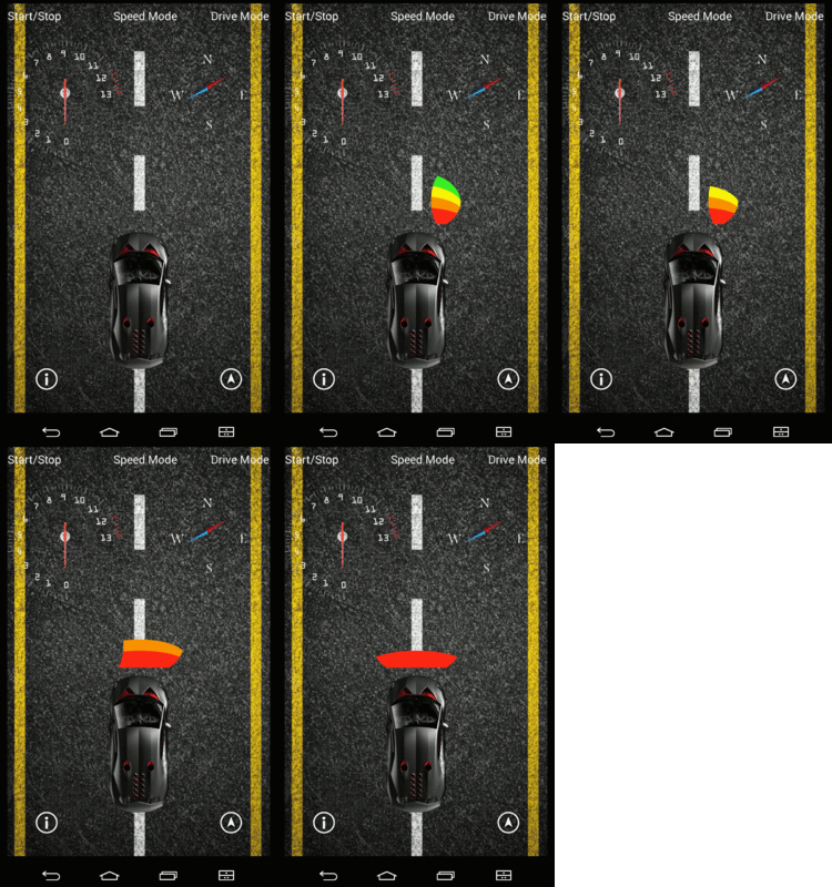
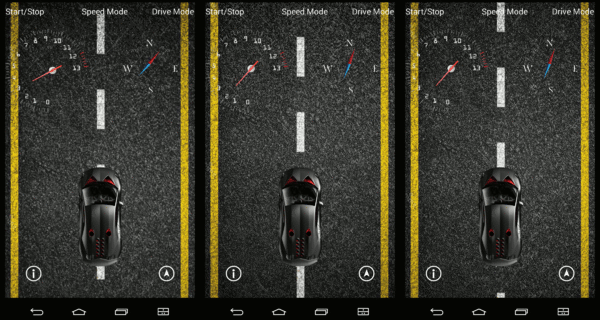
2. A Dashboard view to translate the numeric values of all the sensors into a visual depiction of the speed gauge, compass, sensors and motion of the car
|
This Activity is the home Activity which is the default activity for the application. A lot of information is conveyed as a dashboard on an actual car. For e.g. the analog speedometer rotates the needle from 0-12, which is its high speed. The compass next to the speedometer shows the current heading of the car with respect to magnetic North.
|
The road shown in the background is in fact a dynamic background that changes as per the speed of the car. For this, Frame Animation was used which sliced one image into 4 and repeated these frames at different speeds based on the actual speed of the car. In short, the background will move when the car moves and stop when the car halts.
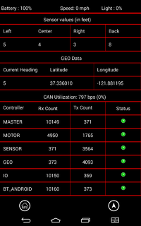
</p> 3. Informational view displaying all the data in a tabular format for debugging purposes
|
Finally, this view shows all the Raw information that the Bluetooth controller intercepts on the CAN bus. It shows the following information:
|
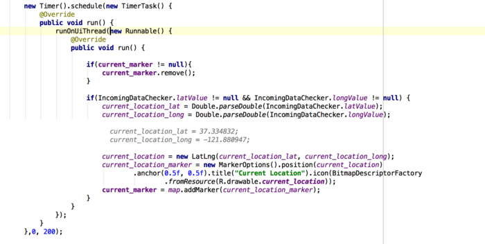
This mode is more useful for debugging purpose since it gives the user the understanding if a particular board is up and running or is down and has stopped sending messages on the bus. Below each Activity are navigation icons, which can navigate from any activity to the other since the number of activities is limited to 3. Each activity uses the TimerTask class to update the UI every 200 ms. A snippet of the Timer Task used in the Google maps activity is shown below:
The above snippet updates the UI every 200ms without any delay. This makes the app more responsive but power hungry. Since we’re only focused on managing the application and not the general performance of the device, this compromise is reasonable.
The application was developed on Android Studio and is compatible with Android devices with screens of 720x1280 pixels or greater and API level 14 or higher (ideally Android 4.4.4).
The format for the messages exchanged between the android application and the controller board can be seen in table:
| S.R. | Command | Code |
|---|---|---|
| 1 | Start | "a$" |
| 2 | Stop | "b$" |
| 3 | Checkpoints | "glat1,long1,lat2,long2$" |
| 4 | Mode: | |
| -Map | "ghome$" | |
| -Home | "gmap$" | |
| -Free Run | "f$" | |
| 5 | Speed: | |
| -Slow | "s$" | |
| -Normal | "n$" | |
| -Turbo | "t$" |
Tablex: Receiving Data from Android
| S.R. | Command | Code |
|---|---|---|
| 1 | Sensor Values | "s1=left_val, center_val, right_val, back_val$" |
| 2 | Speed | "speed=20$" |
| 3 | Compass Reading | "heading=5$" |
| 4 | Current Location | “geo=lat,long$” |
| 5 | Start (from I/O) | “start$” |
| 6 | Stop (from I/O) | “stop$” |
| 7 | Tx Count (All Controllers) | “txcount=1(ctrl ID),,50(val)$” |
| 8 | Rx Count (All Controllers) | “rxcount=1(ctrl ID),50(val)$” |
| 9 | CAN Utilization (bps and %) | “con_util=300,20$” |
| 10 | Light Sensor (%) | “light=10$” |
| 11 | Battery Sensor (%) | “battery=50$” |
Tablex: Transmitting Data to Android
Improvement
In order to have some better portable experience with the connection, it is better to have less devices holding on hand when driving the car. Thus, we can swap the Bluetooth/xBee bridge to BluetoothBee module and so we don’t need to use the SJ One board as a medium/ platform.
The second enhancement is on the Android application which we may have more functions such as controlling the light on/off and intensity. Also, it is better that we can have a debugging feature on the Android such as redirect UART 0 to the Android for remote debugging. Time to destination is also a great feature we would like to put it on the application so the user can know how long would it take from starting point to end point.
Geographical Controller
The geographical controller consists of a 10Gz GPS module and 3- Axis Digital compass IC interfaced to a SJ One board. The geographical controller has the following responsibilities:
- Allow a GPS coordinate to be "set". Based on the set coordinate, calculate, and provide CAN data regarding the current heading, and the desired heading to reach the destination
- This unit needs to compute the "heading degree" to reach the destination.
MTK3339 GPS Chipset
|
This is a MTK3339 GPS chip set with a breakout board from Adafruit. |
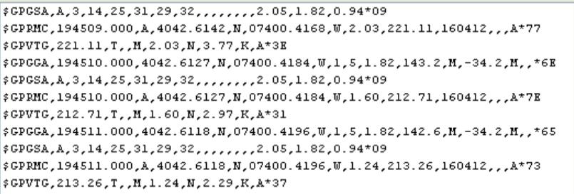 The most common sentences are $GPRMC (Global Positioning Recommended Minimum Coordinates)and $GPGGA. These sentences contain the data such as time, date, latitude, longitude, altitude, land speed and fixt type(number of satellites).
A typical GPRMC sentence is “$GPRMC, 194509.000, A, 4042.6142, N, 07400.4168, W ,2.03,221.11, 1604132,,,A*77 ”. All the geographical data is separated by a comma. The breakup of the sentence is as follows, 19.4509.000 : The current GMT time 19h,45m,09sec,000ms.
A: GPS is active with a GPS lock. If this character is V, it means that this sentence is a void (invalid and all the data is garbage)
4042.6142: Latitude data, 40 degrees, 42.6142 decimal minutes.
N: Polar co-ordinate of latitude N=North, S=South.
07400.4168: Longitude data 74 degrees, 0.4168 decimal minutes.
W: Polar co-ordinate for longitude, W=West, E= East.
2.03: Land speed in Knots.
160412: Current Date eg. 16th April, 2012.
*77= data transfer checksum.
A typical GPGGA sentence is as follows “$GPGGA,194511.000,4042.6118,N,07400.4196,W,1,5,1.82,142.6,M,-34.2,M,,*65” where
194511.000: The current GMT time 19h,45m,11sec,000 ms.
4042.6118: Latitude data, 40 degrees, 42.6118 decimal minutes.
N: Polar co-ordinate of latitude N=North, S=South.
07400.4196: Longitude data 74 degrees, 0.4196 decimal minutes.
W: Polar co-ordinate for longitude, W=West, E= East.
1: fix quality, 0= Invalid, 1= GPS Fix, 2= D-GPS Fix
5: number of satellites in view / locked
1.82: Relative accuracy of horizontal position
142.6,M: Altitude above mean sea level in meters.
-34.2,M: Height of geoid above WGS84 ellipsoid
blank: time since last D-GPS update
blank: DGPS refrence station ID
*65: Checksum
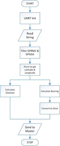
For our project we use $GPRMC and $GPGGA NMEA sentences. They are parsed using string operations to extract and save data. The direction and distance algorithms start using the geographical data once a GPS fix is achieved.We used an external antenna which helped us to get fix.
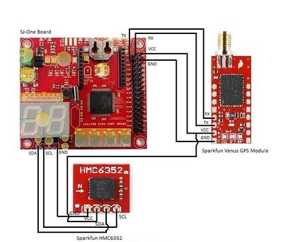
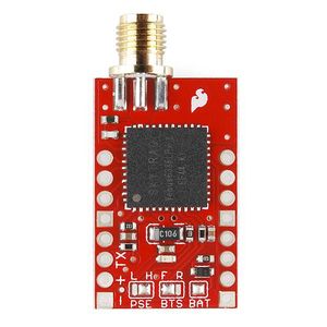
SparkFun Venus GPS
|
Features:
Interface:
|
This is the list of commands which we used for our project.
1. Most Important Factory Reset (In case you screw up :P).
A0 A1 00 02 04 00 04 0D 0A
2. Configure the position update rate of GPS system(10 Hz).
A0 A1 00 03 0E 0A 01 05 0D 0A
3. Configure serial port. this command will set baud rate to 38400.
A0 A1 00 04 05 00 03 01 07 0D 0A
4. Configure NMEA message interval this command will block all strings except GPGGA.
A0 A1 00 09 08 01 00 00 00 00 00 00 01 08 0D 0A
These commands will help a lot, first command will recover your system. second command will increase the update rate to 10 Hz as you need GPS values as fast as possible. third command will increase the baud rate as the update rate has increased so the data sent in one second is increased by 10 times. fourth command will help to simplify the parsing function by reducing the NMEA sentences sent from the module and remove unnecessary data on bus.
|
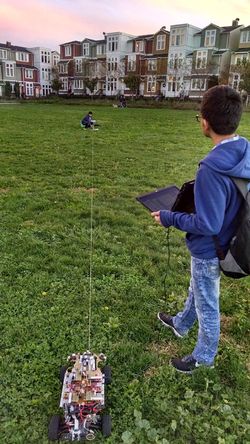
Calibration: The GPS sensor does not require any special calibration. The calibration and the accuracy of the sensor depends on the number of satellites its locked on to. But as we were skeptical about its accuracy and the output of the Haversine formula calculated on Sj-One board we carried out a small experiment. We went to Cahill Park, and fixed a rod in the centre of the ground. then we tied a string one end with the rod and other to the car. We kept circle marked with degrees in the centre and took the readings for angle. we found that the accuracy of our GPS was not good as we could see the fluctuations of 30 to 40 degrees in angle and error of up to 35 feet in distance. so we bought new module from sparkfun. |
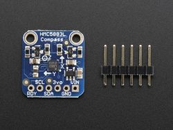
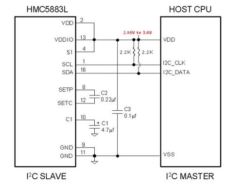
HMC5883L 3-Axis Digital Compass IC
|
This is a HMC5883L Digital compass IC with a breakout board from adafruit.
|
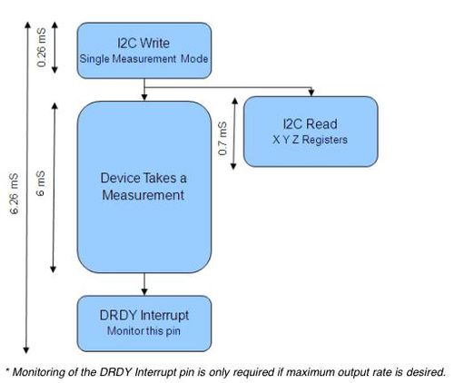
The sensor is used in continuous-measurement mode in which the device continuously takes measurement at user desired rate and updating the output data registers. The master I2C device has to ensure that the data register has to be read before the new data is updated in them. The compass sensor is placed in idle (sleep) mode between measurements to conserve current. The data is placed in 6 data registers, they are
LSB X Data output register
MSB X Data output register
LSB Y Data output register
MSB Y Data output register
LSB Z Data output register
MSB Z Data output register
To reduce the communication between the master I2C device and the compass, the address pointer is updated automatically after a successful read operation. Thereby for read operation only one base address is needed.
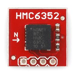
Compass Module HMC6352
|
This compass works on I2C protocol.
For Initialisation we configure I2C Bus at 100 KHz. the slave address for this module is 0x42 for write and 0x43 for read. configure this module in continuous mode. The Operation Mode Byte is located at 0x08 location of EEPROM, set value as 0x02 on this address for continuous mode.the output mode for compass is set to Heading Mode by default. the output is given in precision of tenth of a degree.
Now read the values on address 0x00 where two data bytes are stored which give the heading. |
Calibration:
There are two stages for calibration:
- Calibration of magnetometer.
- Calibration after mounting it on the car.
Magnetometer Calibration: Magnetometer gives magnetic excitation in X-axis, Y-axis and Z-axis. X and Y coordinates are used to calculate the angle with respect to north. Z coordinate gives the amount of declination with the surface of the earth. These values are stored in data output registers. Make a small assembly as shown in figure. Print a circle showing angles at precision of 10 degrees. Make a pointer that can take readings accurately. Align the zero degree on your circle to magnetic north with the help of a compass.
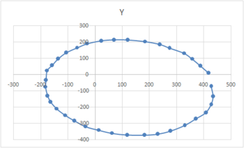
Take readings of X and Y coordinates at interval of 10 degrees and plot X/Y in MS Excel see if the graph is a circle and the centre matches the origin. Generally the centre of the circle is offset, so if you match the centre with origin then compass should work give correct values. To compute the bearing take inverse tangent of (Y coordinate/X coordinate) and convert it to degrees.
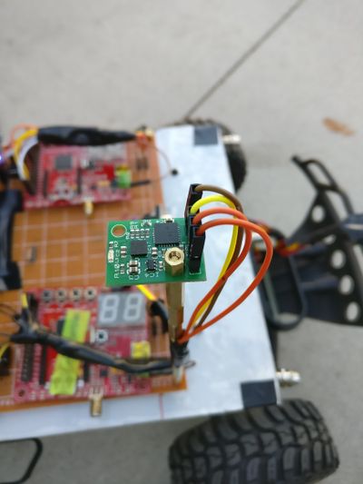
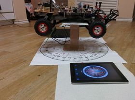
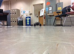
Calibration after mounting it on the car: Keep in mind that magnetometer is just like the magnetic needle in a compass. whenever any kind of metallic device or a device emitting magnetic field is near the magnetometer the readings get skewed. So you need to recalibrate the magnetometer after placing it on the car. Make a bigger version of your previous prototype and recalibrate magnetometer. There are many ways to implement the experiment. two options are shown here. the problem with the first option (figure 1) is that the car is supported on a base and not on wheels. In second option (figure 2) you can see that the car is placed on the wheels. the figure 3 shows how the car is tilted with the weight of batteries. When you keep the car on its wheels you can clearly see the tilt. because of this the value for the magnetometer is affected.
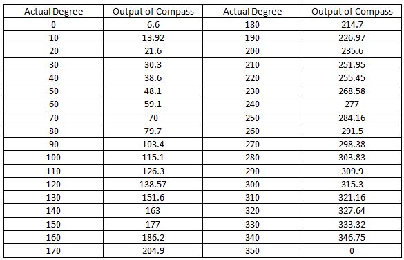
This figure 4 and table shows the output of the compass/magnetometer(HMC5883l) after placing it on the car and using second option to take readings. here we can see that the values of the magnetometer are completely screwed. Instead of circle it gives us ellipse due to which mapping gets very complicated and sometimes unreliable. because of this we tried a new magnetometer from sparkfun(HMC6343) it has built in tilt compensation which uses magnetometer and accelerometer and directly gives values between 0 - 360 degrees, it works like a charm.
Algorithms:
|
1. Distance Algorithm:
The distance algorithm is used to calculate distance between 2 geographical points. In the case of self driving car, it is used to calculate to distance between two checkpoints. We use ‘haversine’ to calculate the distance of two points over a sphere i.e the earths surface. |
Structures
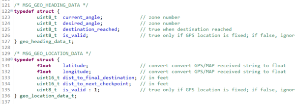
We are using structures to make CAN packets.
geo_heading_data_t:
This structure has two angles desired and current angle which are given in the form of zone (0-19). This structure has two flags destination_reached which tell if the final destination is reached and the valid flag tells that the computed angle is valid. this packet is specially made for MASTER controller. so it can take necessary decisions faster.
geo_loaction_data_t:
This structure is for io and bluetooth module. to display current geographical status of the car. it shows latitude, longitude,distance to next checkpoint,distance to final destination.the valid flag states that the GPS module has FIX and the data is valid.
Code snippets:
get_Compass_HeadingDegrees(void):
This function
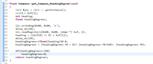
Compass():
This is constructor the class which initializes I2C Bus at 100 KHz.

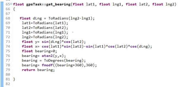
get_bearing( float lat1, float lng1, float lat2, float lng2):
This function computes desired bearing from two geographical points.
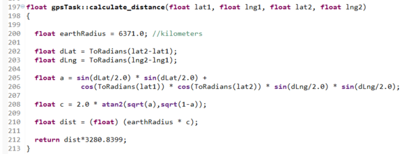
calculate_distance( float lat1, float lng1, float lat2, float lng2):
This function computes distance from two geographical points using Haversines formula.
Technical Challenges:
- GPS: We had to change our module from Ultimate Breakout GPS module Adafruit to Sparkfun venus GPS module as there were issues for GPS Fix in the first module which did not solve even after fixing an external antenna. Sparkfun Venus GPS module is better than adafruit in terms of GPS FIX and accuracy. Note: Its better to buy an external antenna for GPS module, It helps a lot.
- Compass: We had to even change from HMC5883L 3-Axis Digital Compass adafruit to sparkfun HMC6352 Compass module our compass as the values were too erratic as shown in calibration part.
Master Controller
Obstacle Algorithm:
The data coming from the Sensor board is actual distance of obstacle from car in feet. The decision of changing speed and direction of car is made based on the position of obstacle.
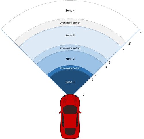
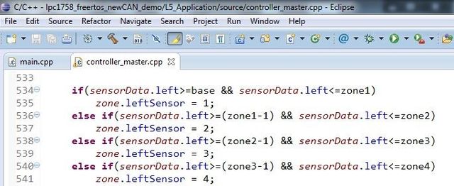
For deciding the speed and direction more precisely, we have divided the total sensor range in four zones. The position of the obstacle is given in terms of zone. Each of the front sensor will determine the zone in which the obstacle lies. Thus the decision making becomes much more simple and efficient.
The boundary of each zone is set depending on the running speed of car. For example at higher speed the range of nearest zone i.e. zone 1is kept large to avoid crashing of the car, while when the car is running at low speed the range of zone 1 is kept small. This helps when car is stopped abruptly when an obstacle is detected in the first zone.
The zones set for the sensors are shown in the below diagram.
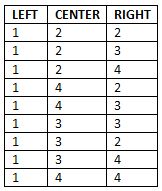
Since there are total 3 sensors at front and each sensor has 4 zones, there are total 43 (64) different possibilities of the position of obstacle. The setting of the zones is implemented using ‘if else’ statements. We found two ways to develop the algorithm for obstacle avoidance. We have implemented both algorithms, but because of time constraints we couldn’t refine the 2nd algorithm which lead us to use the following algorithm. This algorithm is developed by computing all possible combinations of 4 different zones of 3 sensors. The possible combinations can be generated using a simple C program. For a particular zone, specific speed and direction of motor and servo can be set. After setting the speed and direction, we sorted all the combinations which require same speed and direction. By checking zone values of 3 different sensors, a condition can be implemented using AND (&), OR (|) and NOT (!) operation. As an example, we developed the condition for FULL RIGHT turn as follows.
These are the probable zones for the FULL RIGHT turn since an obstacle is detected in lefts sensor’s zone1. For this particular turn, a condition can be developed as simple as (L == 1) (Left sensor zone == zone1). So if this condition is present, motor board will be instructed to make a FULL RIGHT turn. Using this method the algorithm is developed.
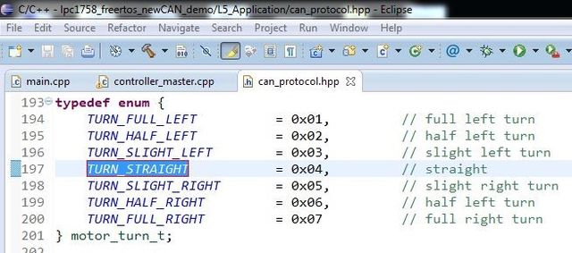
Initially we had only 3 turns for servo viz. FULL RIGHT, STRAIGHT, FULL LEFT. But as we started developing the algorithm and we came up with 4 more turns. So total possible turns are as follows.
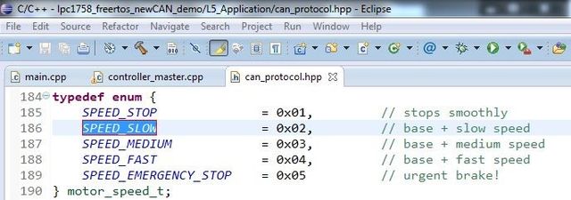
The values in the second column are data values which are sent to motor controller. These enums are part of the can_protocol.hpp file which is the common header file used for all modules.
Similarly we have 3 different speeds shown below.
Emergency stop is used for emergency cases where an obstacle is very near to car or a sudden change in obstacle state occurs.
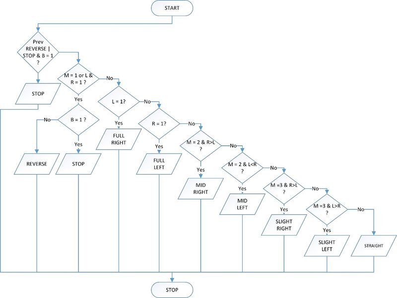
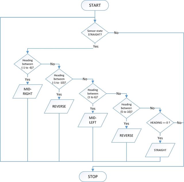
After developing the algorithm depending on the following turns and speed, the flowchart of the algorithm is as shown in the below diagram.
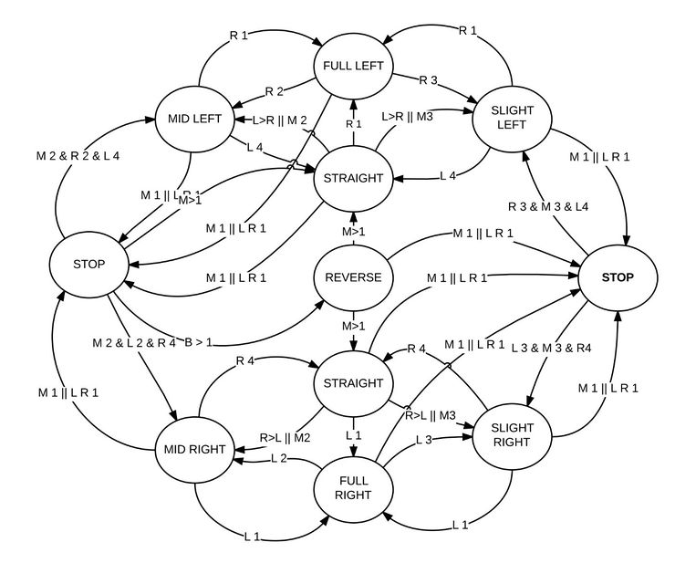
The algorithm is implemented using ‘if’ and ‘else if’ statements. Since we have many possibilities of states and their transition, complete state diagram will be very complicated to draw and explain. The most common states and state changes are shown in the following state diagram. The excitation/inputs to the states are the value of sensor readings (zones in our case). According to the excel sheet formed for the logic, respective state transition is done.
GPS Algorithm:
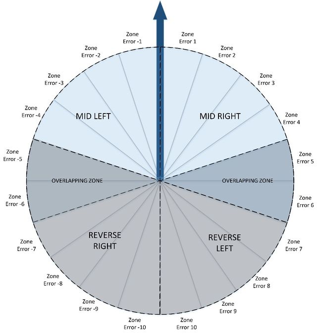
After successful testing of the obstacle avoidance algorithm, algorithm for the compass and GPS was developed. Compass reading is divided into 20 different zones by the Geographical controller (Each zone consists of 18o).The GPS data is distance to next checkpoint. So the Master controller does not have to keep track of the all the intermediate checkpoints. Geographical controller will request for the next checkpoint to the Bluetooth (Bridge) board once the current checkpoint is reached (i.e. remaining distance is less than the threshold). If we are heading to a particular zone, the desired zone can be one of the 18 zones. The maximum error or the correction required to head to the desired zone will be 10. For example if we are moving in zone 5, the maximum correction we could do is towards zone 15. So the maximum error/correction is 10.
For heading to the correct zone (desired zone) a factor of 20 is added to the difference of current and desired heading. This will give the correction depending on which we are changing the motor direction and turn if wheels.
The maximum correction/heading could be -10 or 10. ‘If’ and ‘else if’ sentences are used to implement this algorithm. The decision taken with this algorithm is explained using the following diagram. The arrow indicates the current moving direction and remaining values are the maximum possible error/correction. The decision taken for the respective error is displayed in the corresponding error range. There is need of having overlapped error ranges to avoid the deadlock which we have experienced during testing.
CAR Resume/Car Pause:
When a master module’s CAN RX process task receives CAN message MSG_CAR_RESUME, it calls its respective message handler. This message handler will further set the disable bit ‘car_paused’ which triggers the obstacle avoidance algorithm and starts the car.
Likewise when MSG_CAR_PAUSE is received, it enables the ‘car_paused’ bit and car will stop. IO module and Bluetooth both can send these messages and control the car start and stop.
GEO Data Valid:
On the reception of ‘is_valid’ bit from MSG_GEO_DATA message, GPS algorithm starts and bearing is computed from ‘current_angle’ and ‘desired_angle’. The ‘destination_reached’ field from MSG_GEO_DATA is used to stop the car after reaching the destination.
Software Implementation:
Enumerated datatypes for motor Speed, Directions and Turn can be seen form the following snippets codes.
Speed emergency stop is used when the obstacle position is very near and there is chance of a collision. Both master and Motor module has the common enumerated data types so that changing a common file will be enough to change the message numbers.
The above snippet is for wheel direction, Forward of Reverse.
Above data type is used for different turns of synchro motor. To move front wheels at various positions for fine and full turns. The following code snippet shows the implementation of setting sensor zone.
The implementation of obstacle avoidance is done using a state diagram and GPS algorithm is done using ‘if else’ statements. Following code snippet shows the implementation of both the algorithms.
Schedule
| Sl. No | Start Date | End Date | Task | Status | Actual Completion Date |
|---|---|---|---|---|---|
| 1 | 09/14/2014 | 09/20/2014 | Understanding the logic of sensors to be used | Completed | 09/20/2014 |
| 2 | 09/21/2014 | 10/04/2014 | Writing the codes for the different types of sensors | Completed | 10/04/2014 |
| 3 | 10/05/2014 | 10/11/2014 | Testing the different sensors for accuracy and placing the order for the one we have selected. | Completed | 10/11/2014 |
| 4 | 10/12/2014 | 10/25/2014 | Build CAN transceiver and send data to the Master Board | Completed | 10/25/2014 |
| 5 | 10/26/2014 | 11/01/2014 | Place all the sensors on car and test for obstacle avoidance | Completed | 10/28/2014 |
| 6 | 11/02/2014 | 11/14/2014 | Work on light and tilt sensors | Completed | 11/04/2014 |
| 7 | 11/15/2014 | 12/09/2014 | Final testing and debugging | Completed | 12/19/2014 |
| Sl. No | Start Date | End Date | Task | Status | Actual Completion Date |
|---|---|---|---|---|---|
| 1 | 09/14/2014 | 09/20/2014 | Understand the logic of Motor Controller present in the RC Car | Completed | 09/20/2014 |
| 2 | 09/21/2014 | 09/27/2014 | Replace on-board controller with SJSU One board | Completed | 09/22/2014 |
| 3 | 09/28/2014 | 10/04/2014 | Drive the DC motor with SJSU One board at different Duty Cycles | Completed | 09/30/2014 |
| 4 | 10/05/2014 | 10/11/2014 | Test the Servo and DC motor together for moving forward and taking turns | Completed | 10/09/2014 |
| 5 | 10/12/2014 | 10/18/2014 | Build CAN Transceiver and move the car as per the CAN message received | Completed | 10/13/2014 |
| 6 | 10/19/2014 | 10/25/2014 | Make arrangement for CAN subscription task | Completed | 10/25/2014 |
| 7 | 10/26/2014 | 11/01/2014 | Interface encoder and calculate the actual speed at which car is running | Completed | 10/28/2014 |
| 8 | 11/02/2014 | 11/08/2014 | Make compensation algorithm and make car to move at desired speed | Completed | 11/04/2014 |
| 9 | 11/09/2014 | 12/09/2014 | Final testing and debugging | Completed | 12/19/2014 |
| Sl. No | Start Date | End Date | Task | Status | Actual Completion Date |
|---|---|---|---|---|---|
| 1 | 09/14/2014 | 09/20/2014 | Search and order GLCD module with touch screen, LEDs for headlights | Completed | 09/20/2014 |
| 2 | 09/21/2014 | 10/04/2014 | Study of GLCD data frame formats and design GUI | Completed | 10/03/2014 |
| 3 | 10/05/2014 | 10/11/2014 | Development of GLCD functions including touchscreen handler | Completed | 10/11/2014 |
| 4 | 10/12/2014 | 10/25/2014 | Setup CAN subscription tasks for communication with Master controller | Completed | 10/27/2014 |
| 5 | 10/26/2014 | 11/01/2014 | Develop hardware and code for automatic headlight control. | Completed | 11/01/2014 |
| 6 | 11/02/2014 | 11/14/2014 | Build hardware for switches and write interrupt handlers for the same | Completed | 11/07/2014 |
| 7 | 11/15/2014 | 12/09/2014 | Mount GLCD, headlights, switches on car and final testing | Completed | 12/19/2014 |
| Sl. No | Start Date | End Date | Task | Status | Actual Completion Date |
|---|---|---|---|---|---|
| 1 | 09/14/2014 | 09/20/2014 | Google maps API research | Completed | 09/20/2014 |
| 2 | 09/21/2014 | 10/04/2014 | Mock locations on Google maps and simulate co-ordinates w/o gps | Completed | 10/04/2014 |
| 3 | 10/05/2014 | 10/11/2014 | Two way Bluetooth communication and setup RTOS tasks | Completed | 10/11/2014 |
| 4 | 10/12/2014 | 10/25/2014 | Raw GUI for app and setup CAN tasks for Start and Stop commands | Completed | 10/25/2014 |
| 5 | 10/26/2014 | 11/09/2014 | Integration with GEO module and queue for each subscribed service | Completed | 11/09/2014 |
| 6 | 11/10/2014 | 11/16/2014 | Incorporate all essential services into Android app and test for response | Completed | 11/16/2014 |
| 7 | 11/16/2014 | 11/23/2014 | Final setup and changes for all the CAN tasks along with XBee interfacing | Completed | 11/23/2014 |
| 8 | 11/24/2014 | 12/01/2014 | Testing with GEO module with real-time co-ordinates and plotting way points onto Maps | Completed | 12/01/2014 |
| 9 | 12/02/2014 | 12/09/2014 | Final Testing and verification of all components on the main field | Completed | 12/19/2014 |
| Sl. No | Start Date | End Date | Task | Status | Actual Completion Date |
|---|---|---|---|---|---|
| 1 | 09/7/2014 | 09/14/2014 | Market research for GPS and Compass Modules | Completed | 09/14/2014 |
| 2 | 09/14/2014 | 09/21/2014 | Place order / receive the modules | Completed | 09/20/2014 |
| 3 | 09/21/2014 | 09/28/2014 | Interface GPS with SJ -One board via UART | Completed | 09/26/2014 |
| 4 | 09/28/2014 | 10/05/2014 | Interface Compass with SJ-One Board via I2C | Completed | 10/03/2014 |
| 5 | 10/05/2014 | 10/12/2014 | Parsing the GPS data stream | Completed | 10/11/2014 |
| 6 | 10/12/2014 | 10/19/2014 | Calibration and testing of compass | Completed | 10/13/2014 |
| 7 | 10/12/2014 | 10/19/2014 | Decide CAN message ID’s and message formats | Completed | 10/28/2014 |
| 8 | 10/19/2014 | 10/26/2014 | Combining UART and GPS parsing. Create task for GPS | Completed | 10/25/2014 |
| 9 | 10/19/2014 | 10/26/2014 | Combining compass calibration and i2c interface. Create task for Compass | Completed | 10/25/2014 |
| 10 | 10/26/2014 | 11/02/2014 | Distance to Destination Calculation and Algorithm | Completed | 11/02/2014 |
| 11 | 11/03/2014 | 11/10/2014 | Basic CAN communication with Master, IO and Android | Completed | 11/10/2014 |
| 12 | 11/10/2014 | 11/17/2014 | Synchronization and Data Integrity (Semaphores/Mutex/Critical Section) | Completed | 11/17/2014 |
| 13 | 11/18/2014 | 11/25/2014 | Final Integration of CAN Framework and Implementation of CAN communication with other modules | Completed | 11/25/2014 |
| 14 | 11/26/2014 | 12/09/2014 | Testing and debugging on car (Re-Calibration/Bug Fixes) | Completed | 12/19/2014 |
| Sl. No | Start Date | End Date | Task | Status | Actual Completion Date |
|---|---|---|---|---|---|
| 1 | 09/7/2014 | 09/13/2014 | Understanding CAN Bus and API's | Completed | 09/13/2014 |
| 2 | 09/14/2014 | 09/20/2014 | Deciding System Flow | Completed | 09/20/2014 |
| 3 | 09/21/2014 | 09/27/2014 | Deciding MSG id's for all devices | Completed | 10/27/2014 |
| 4 | 09/28/2014 | 10/11/2014 | Testing Subscription between 2 devices | Completed | 10/4/2014 |
| 5 | 09/28/2014 | 10/11/2014 | Making CAN bus hardware to interface all SJOne boards | Completed | 10/11/2014 |
| 6 | 09/28/2014 | 10/11/2014 | Testing subscription and time sync between all devices | Completed | 10/11/2014 |
| 7 | 10/12/2014 | 10/18/2014 | Reading sensor data from boards at the subscription rate | Completed | 10/26/2014 |
| 8 | 10/19/2014 | 11/1/2014 | Algorithm for obstacle avoidance | Completed | 10/27/2014 |
| 9 | 11/2/2014 | 11/15/2014 | Algorithm for GPS based navigation | Completed | 11/15/2014 |
| 10 | 11/16/2014 | 11/22/2014 | Initial testing and tweaking of the car | Completed | 11/22/2014 |
| 11 | 11/23/2014 | 12/9/2014 | Final Testing! Showdown time! | Completed | 12/19/2014 |
Future Enhancement
Conclusion
Project Video
Project Source Code
References
Acknowledgement
The hardware components were made available from Amazon, Sparkfun, Adafruit, HSC, Excess Solutions. Thanks to Preetpal Kang for providing right guidance for our project.
References Used
- LPC_USER_MANUAL
- Ultrasonic Sensor
- ADC Sensor
- GLCD with Touchscreen
- XBee Module
- Bluetooth Module
- GPS Module
- Compass Module
- CAN Transceiver
- Linear Voltage Regulator
- Socialledge Embedded Systems Wiki
- Preetpal Kang, Lecture notes of CMPE 243, Computer Engineering, Charles W. Davidson College of Engineering, San Jose State University, Aug-Dec 2014.
- en.wikipedia.org/
