F14: Collision Avoidance Car
Contents
Collision Avoidance Car
Abstract
The inspiration behind the Collision Avoidance Car project comes from the state-of-the-art field of self-driving cars. All major automotive companies are investing heavily in autonomous car technology. One of the more prominent autonomous cars being developed is the Google Car, which features Lidar and photo-imaging technology to implement autonomy. The goal of the self-driving car is to reduce gridlock, eliminate traffic fatalities, and most importantly, to eliminate the monotony of driving. This project will explore the fundamentals of Lidar, and how this technology is being used for cutting-edge products, such as the Google Car.
Objective & Scope
The project objective was to implement Lidar(laser-based device for measuring distance) technology, coupled with a toy car, to autonomously detect and avoid obstacles. The car operates in two modes: automatic and manual. In the automatic mode, the car maneuvers around autonomously, avoiding obstacles to the front, rear, and sides. Whenever an obstacle is detected, the car maneuvers in the opposite direction, as long as that direction is also free of obstacles. In the manual mode, the car's movements are controlled via a Bluetooth connection. In addition to direction controls, a user is able to adjust the speed of the car and to adjust the distance at which obstacles are avoided.
Team Members & Roles
Eduardo Espericueta - Lidar Unit Integration
Sanjay Maharaj - Hardware Integration & System Wiring
George Sebastian - Software Infrastructure (tasks / movement logic) & Bluetooth Integration & Lidar
Introduction
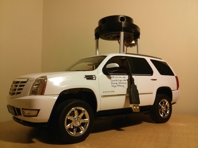
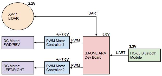
The purpose of this project was to modify an RC car with the intent of being able to control the car using Bluetooth, as well as implementation of an autonomous mode. This project consisted of the toy-car platform, SJ-ONE microcontroller, Bluetooth module, and a Lidar unit. The toy-car chosen for this project had a spacious platform-area, which was necessary to accommodate all of the components used. The Cadillac Escalade toy-car purchased from Amazon in particular was easy to work with, as it had DC motors for both driving the rear wheels, and steering left or right. It also had LEDs, a switch, and a battery pack that could easily be repurposed for our project. All of these components were originally wired to a PCB from the factor, which was removed from the toy-car and the wires repurposed to the SJ-ONE board. Both DC motors worked well with a +/- 7 volt supply.
The radio antenna that was originally integrated to the RC car was removed, and in its place a Bluetooth module was integrated to the new system in order for a user to communicate with the toy-car. The Bluetooth module was interfaced to the SJ-ONE board over UART, and allowed for serial terminal emulation through pc, or even smartphone applications. This enabled commands to be sent to the vehicle wirelessly and on the fly.
The Lidar used for this project is a spare-part that comes from the Neato XV-11 Vacuum, which is an autonomous vacuum. The device is officially known as the Picolo Laser Distance Scanner, and is produced by Neato Robotics, Inc. The device is used to measure the distance to objects that are in the area of operation. In contrast to more expensive Lidar units on the market, the Picolo Lidar unit does not measure the time that it takes for a ray of light to exit and return to the unit, but instead determines the distance to an object through triangulation. The Lidar unit was purchased as a spare part on eBay, and did not come with any documentation. However, there is a large community of hackers who have well-documented information on the Piccolo Lidar across many websites.
Design Implementation
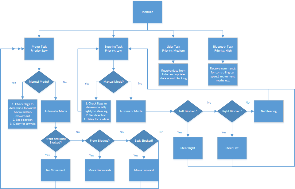
The state machine above shows a high level working of the autonomous car. The car's software infrastructure is made up of four tasks: the motor task, the steering task, the Lidar task, and the Bluetooth task.
The Bluetooth task is in charge of receiving commands from a computer or a phone to control the autonomous car. There are many Bluetooth commands, including:
- Switch between manual and automatic driving mode.
- Steering and movement (for use in manual mode).
- Movement speed adjustments (faster or slower).
- Steering speed adjustments (faster or slower).
- Change threshold values used in logic for dynamic calibration.
The Lidar task continuously runs and updates a global array with information about obstacles at every degree. The movement task will move the car forward or backward based on flags set by the Bluetooth task while in manual mode. The steering task behaves similarly when in manual mode except it moves the car left and right. In automatic mode, both cars will compare threshold values with the global array the Lidar task populated to make its decision to move.
System Integration
Bill Of Materials
| Component | Quantity | Cost (EA) | Source |
| Neato XV-11 LIDAR Unit | 1 | $90.00 | eBay |
| 1/14ths Scale Cadillac Escalade RC Car | 1 | $40.00 | Amazon |
| SJ-ONE ARM Development Board | 1 | provided | SJSU SCE |
| SJValley PWM Motor Controller | 2 | provided | SJSU Parts Bin |
| Buck Converter for Voltage Conversion | 2 | $5.99 | Amazon |
| LM7805CT 5V Voltage Regulator | 1 | $0.40 | Mouser |
| HC-05 Bluetooth Module | 1 | $7.99 | Amazon |
| Radioshack Battery Pack 12V | 1 | $2.99 | RadioShack |
Verification
To further understand how distance data compared to the physical distance of an object, values of the 0,90,180, and 360 degree points were printed to the screen while an object was placed at various distances. While testing, it was found that the LIDAR's data is erroneous if the vehicle is moving too fast. This is most likely due to the point at which the IR laser is emitted having moved with the speed of the vehicle sooner than the point at which the IR laser is received to compute a distance at some degree. After the vehicle was slowed down, the LIDAR unit returned consistent data, and the vehicle maneuvered very consistently.
Technical Challenges
1. The SJValley PWM Motor controllers that were used operate on a minimum input voltage of 7V.
2. The LIDAR DC Motor will only output data consistently between 240 and 300 RPM, so a constant 3.3V supply is recommended.
3. Lidar values can be corrupted and those values should be discarded in software.
4. The Firmware for the LIDAR can be interacted with over a serial connection, but is not easily utilized.
5. It is important to note that the printf function is costly when debugging at a 115200 baud rate.
Future Enhancements
Currently the device only uses some of the available Lidar data when driving autonomously. Much more complex driving patterns and obstacle avoidance could be possible if more of the data points are used. This could potentially eliminate blind spots the car might have. Further enhancements could come in the form of:
- GPS support so the car can drive autonomously.
- Some form of memory so the car can remember obstacles and form some kind of intelligent routing mechanism.
Conclusion
After validating the idea of an easily maneuverable RC car by a manual driving mode interfaced over bluetooth, and working to receive valid data from the LIDAR unit, both components were combined and development of an obstacle avoidance algorithm was started. The algorithm for collision avoidance was designed in written in less than one day, but was demonstrated to a large group of graduate and undergraduate students successfully. Further work on the collision avoidance algorithm could make this vehicle more aware of it's surroundings, and this vehicle could also serve as a platform on which to begin experimenting with machine learning techniques.
References
xv11hacking LIDAR Resources: https://xv11hacking.wikispaces.com/


