S12: FreeRTOS based QuadCopter
Contents
FreeRTOS-based Quadrocopter with Real-Time Flight Data
Abstract
Our CmpE 146 project involves the assembly of a FreeRTOS -based quadrocopter. Our quadrocopter will be able to provide real-time flight diagnostic data with the help of a couple of XBees. The quadrotor will house one of the XBees and the other XBee will be connected to an ARM LPC2148 board that is on the ground, next to the person flying. Data received on the local board is communicated to the host PC over UART. Flight is made possible with the help of generic radio control (or RC), and the inputs will be sent from the transmitter to the receiver. A flight controller board will receive those inputs and make the necessary adjustments to implement the desired function.
Objectives & Introduction
Our team wanted to build a custom quadcopter that is governed by a FreeRTOS-based firmware. Our team used the Afroflight Naze32 flight controller, which has a 32-bit ARM Cortex M3 based processor. The firmware for it is based on a very popular codebase called MultiWii originally developed for commanding and controlling a quadcopter with Nintendo's Wii peripherals. The board contains 2 UART outputs - one for the USB-to-Serial converter for easy setting up and debugging with a PC. For the second UART to be available, this USB-to-Serial bridge has to be bypassed and replaced with XBee since for some reason the current iteration of the board does not support multiple simultaneous UART channels.
Data sent over this UART is received via Xbee on the LPC2148 board which can then be retransmitted over another UART channel. This re-routed data can be monitored using the popular C#-.NET based GUI front end called mw-wingui (MultiWii WinGUI). The program looks for data from the flight controller over the available COM ports and grabs packets of data which are then parsed and displayed on the screen appropriately. The data can also be received over Hercules with the help of a custom parser.
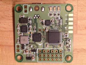
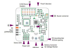
A picture of the flight controller is shown to the right - it is extremely small, measuring 36mm x 36mm and features a rich variety of sensors:
- MEMS Gyroscope
- MEMS Accelerometer
- 3-axis Magnetometer
- Pressure Sensor
Inputs are received from a rather old Futaba Conquest Transmitter FP-T6NPK operating at 72MHz. The transmitter encodes the PWM waves as PCM, generally using a 1024 bit resolution. This signal is decoded by the receiver that usually comes with the transmitter (hence the reason why datasheets for receivers alone are hard to find - they are generally paired with a corresponding transmitter which generally also has a datasheet). The output from the receiver is pure PPM for every channel.
Team Members
- Yoni Klein
- Amol Mundayoor
- Raymond Buckman
- Michael Leung
Roles & Responsibilities
Amol Mundayoor - Parts research and acquisition, Parts assembly
Michael Leung - Software integration, Parts assembly
Raymond Buckman - Flying mechanics research, Parts assembly
Yoni Klein - Software integration, Parts assembly
Parts List & Cost
| PARTS | COST |
|---|---|
| FunFly Naze32 | $70 |
| ARM LPC2148 board | $90 |
| 4x 924kV motors | $80 ($20 each) |
| 4x DYS 30A ESC | $72 ($18 each) |
| 2x APC 1047 Propellers (Counterweighted Set) | $15 ($7.50 each) |
| ST450 Aluminum Quadcopter Frame | $35 |
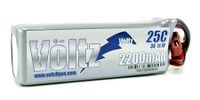
| 2200 mAh LiPo Battery | $20 |
| LiPo Battery Charger | $40 |
| PCM Receiver/Transmitter | Borrowed (nominally $50-$100) |
Design & Implementation
The Copter Build Instructions
Assuming that all the parts have been gathered, here is the relatively detailed instruction set on how to go about building this quadcopter. When done, the copter will have the wheelbase (diameter of the quadcopter when measured from the axis of any two opposing propellers) of the frame (450mm).
Motor Installation
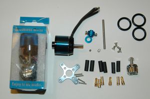
The picture on the right show the motor used, along with all the parts that come with it. The three black wires coming out of the motors go to the Electronic Speed Control (ESC). The order of the wires do not matter if you are using brushless motors and brushless ESCs (which is what you should be using on quadcopter builds anyway!). The four-pronged eight-holed plate goes under the motor between the frame - it's the motor mounting plate. The steel "crown" on the bottom right hand side next to the heatshrink is the propeller mount - it goes on top of the shaft, propeller goes on top, and the nut is tightened down so that the props don't come off during flight. There are some extraneous parts in the kit that can be considered as "spares".
Motor Mounting
Once the motor is assembled, they can be simply mounted on the frame using the motor mounting plate as described in the previous section. It is pretty straight forward - washers and lock nuts can be used to eliminate vibration since motors are the ones providing the most of the vibration in a copter system. DO NOT MOUNT THE PROPELLERS UNTIL THE VERY END - ONLY WHEN THE COPTER IS READY FOR FLIGHT TEST
ESC Connections
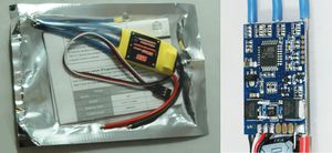
The three blue wires coming out from the ESC are to be connected to the 3 wires on the motor. These connections have to be very well made because they'll be handling many many amps of current. Extending the wires were not necessary, and we recommend not extending them until absolutely necessary. The red and black wires are the battery wires - red is positive and black is ground. These connections are done using bullet connectors and here is an excellent tutorial on how to solder them. Once those connections are done, the only wire left to take care of is the 3-pin wire. We recommend buying ESCs that have a BEC (Battery Eliminator Circuit) in them. When connecting such ESCs, only have the red wire from one ESC connected - all the other red wires from the other three ESCs are to remain disconnected.
ESCs are REQUIRED to be calibrated before using. There are different ways of calibrating an ESC depending on the brand and model. ESCs need to be calibrated individually. There are more information about ESCs calibrations online.
Flight Controller Connections
The picture on the right shows the flight controller connection interface. The manual on the abusemark store has more detailed information about what the flight controller is capable of. For our purposes the 3-pin header on top of the flight controller is sending the signal to the ESCs which then control the motors. The signals come from the RC Input headers, with the * being 5V, the 8 pins to the right being RC signal from the RC Receiver and the lone pin on the left is ground. Our Xbee was also powered using this 5V connector.
Power Distribution
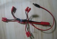
Power distribution can be tricky - we have one main source of power, which is a LiPo battery. This lone source is to be distributed among the ESCs - the best way to do this is with the help of a power spider. Once the spider is made, the connections are super straightforward and simple - power goes to power and ground goes to ground.
Hardware Design
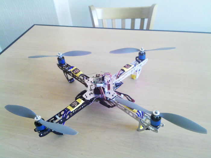
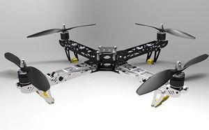
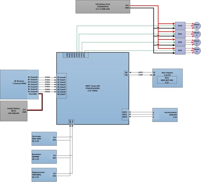
The quadrocopter consists of a frame, a flight controller board, battery, RC receiver, four motors, and four propellers. All the components are mounted on the aluminum frame, which is “X”-shaped. There are three major components mounted at the center of the frame. They are: the Naze32 flight controller board, the battery and the RC receiver. A motor is mounted at the end of each arm of the frame. The flight controller board and battery are interfaced with the motors through electronic speed controllers (or ESCs). ESCs are responsible for controlling the speed and direction of each motor. Each motor is equipped with a 10 inch diameter propeller. A propeller’s measurements are designated by their diameters and pitch. The propeller’s diameter size determines the thrust power. A larger propeller generally generates more thrust than a smaller propeller at the same RPM. When a propeller spins at a high RPM, it will generate more noise and vibration. The pitch determines how far the propeller will move per single revolution of the motor. It is important to note that propellers that sit opposite of each other rotate the same direction. Therefore, one pair of propellers will be rotating clockwise while another pair will be rotating counterclockwise.
Quadrocopter movement is controlled by the motor rotation speed. Obvious movements, such as vertical movement, are controlled by increasing or decreasing the rpm of all four motors. To push the quadrocopter in a certain direction horizontally is done by only adjusting the motors along the axis of movement. The rotation speed of the motor that “pushes” the quadrocopter in a certain direction is increased, while the opposite motor’s rotation speed is decreased. As said earlier, the other two motor speeds are not adjusted. Calibrating all four motors in this fashion forces the quadrocopter to lean toward the side of the motor with the lowest rotation speed, and moves it in that direction. To rotate the quadrocopter in a certain direction, the motors of the propeller rotating in that direction need to be increased. Pitch and roll are accomplished by performing the same action as moving the quadrocopter horizontally.
The frame used was a factory made ST450 frame from Hobbycool. The frame is made in China and has some amount of portability - there are hex nuts that can be loosed to change the X format of the copter to an = format by folding the legs. The drawback is that the nuts have to be tightened every time the copter is to be flown. This can be quite inconvenient especially when all the parts are mounted. Hence a folding copter frame does not add any value to the build and can sometimes be conceived as less ideal. The frame comes with 4 10" propellers but they did not fit the motors we had (and better propellers were on hand).
The motors shown in the picture on the left are not the motors used in this build. The motors used in this build are shown on the right, and they produce 924rpm per volt (unit is kV, not to be confused with kiloVolt). This means that when powered with the minimum 7V each motors spin at approximately 6500rpm. When testing the copter it is now clear that the propellers should be removed. It also makes it easier to work around the little corners since there is minimal space.
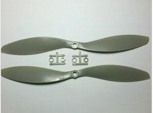
The propellers used were molded plastic propellers since they provided the best cost to performance ratio. The propellers come in matched sets - one rotates clockwise and the other rotates counter clockwise. The matched set has propellers identified as 10x4.7P and 10x4.7 - the propellers marked as P are "pushers" where they rotate counter-clockwise.
Hardware Interface
The flight controller used is called "Naze32" - it is based on an ARM Cortex M3 32-bit microcontroller. The firmware is available as an open source project hosted at Google Code which can be checked out using subversion (or browsed using the "Browse" link). The firmware communicates with MultiWii and its .NET GUI counterpart MultiWii-WinGUI. WinGUI communicates over UART to get data from the flight controller, and has a real time graphical representation of data being fed to the speed controllers and motors, along with the strength of RC input. RC input varies from 1000 - 2000, measured in milliseconds due to the nature of a PWM/PPM pulse.
The Naze32 Flight controller board is the intersection of all connections. Everything that is used to operate the quadrocopter is essentially linked to it. To have the quadrocopter perform a function, we need to tell it what to do first. This is done by using the RC transmitter (remote controller). The RC transmitter uses radio signals to communicate with the RC receiver, which is mounted on the quadrocopter frame. When the joysticks of the RC transmitter are moved, it completes a circuit to an IC, which generates a set sequence of electrical pulses. The sequence contains a set of pulses that corresponds the movement, indicated by the joysticks on the RC transmitter. The RC receiver receives these sequences of pulses and decodes them. Depending on the width of each pulse in a set sequence, the function of the quadrocopter will change. This kind of communication-control technique is called PWM, pulse width modulation. An analogy of this technique would be two friends trying to communicate with each other by whistling. Depending on the duration of the whistle, a different message will be delivered. For example, a continuous whistle of 2 seconds could mean “walk forward” and 5 seconds could mean “walk backward”.
The RC receiver sends the decoded PWM to the flight controller and then it powers the ESCs accordingly. The connections of the ESCs play a vital role in powering everything. The ESCs in our inventory are integrated with BECs, Battery Eliminator Circuit. BECs allows the flight controller board and RC receiver to be powered without an extra battery. Here’s how it works: the main battery is connected to the ESCs and the ESCs uses that same battery supply to power the board. This is done by connecting one (one is all that’s needed) of the ESCs’ BEC wire to the flight controller.
On the other end of the ESCs are three of the same wires. These wires are used to power the brushless motor. These three wires can be connected one-to-one to the wires of the brushless motor in any combination. When connected and powered, the brushless motors will spin in one direction. If you are not satisfied with the direction of the motor, then this could be change by switching connection between any 2 of the 3 wires.
Software Design and Implementation
Our flight controller board uses FreeRTOS to control communication between sensors and peripheral devices. The code for this board is GPL based and we have utilized it for this project. Our goal was to interface this board with our LPC2148 board for debugging and data logging. We also interfaced our boards with an already existant GUI software that shows real time flight data and sensor readouts. Communication from the flight controller board to the LPC2148 board and GUI was made over UART using a drop-in XBee wireless UART bridge. The ultimate goal was to have the flight controller board send wireless data to our LPC2148 board. With that data, we would perform data logging functions as well as forward the data to the GUI on our PC. Unfortunately, we were only able to forward the data to a terminal with this configuration. However, we were successful in interfacing the flight controller board with the GUI over Xbee directly. As such, this section will provide design and implementation details for both separate functions.
Flight Controller Board
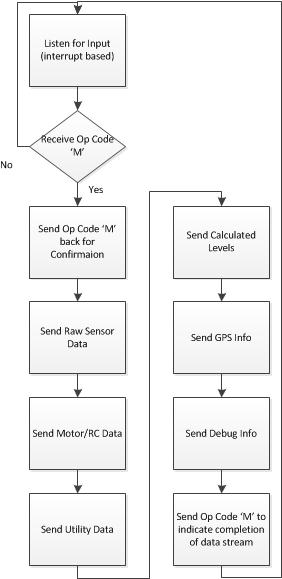
Our flight controller board is capable of sending data in different formats for different devices (arduino, bluetooth, or raw data for the GUI). We are using the full stream of raw data that is compatible with the GUI software we want to utilize. In the flight controller's main loop, it waits for certain 'op codes' to send back appropriately formatted data. This process is interrupt driven and sends data over UART. In this case, our op code of interest is 'M'. This causes the following steps to be performed until completion.
LPC2148 Board and GUI Interface
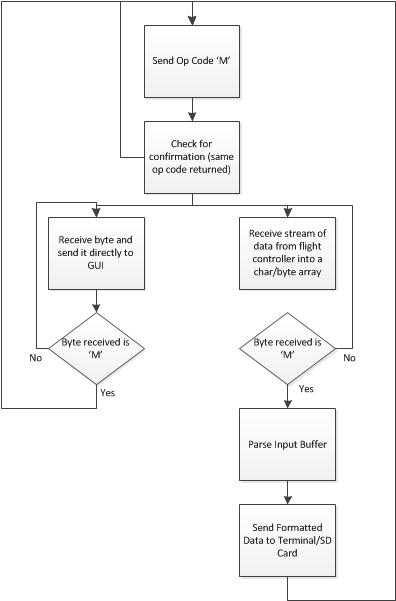
Our board used only one task. We chose to modify the already existant userInterface task given in our lab because it already uses interrupts and is setup to use UART0. We had to write a driver for UART1 in order to receive data from the flight controller board (using Xbee). Once received, we had to parse the data into appropriate sized containers and then forward that to a terminal or SD card. We also interfaced the board directly through UART to the GUI software we were using. This was as simple as creating a wireless UART bridge between the flight controller board and our PC. Once done, we used the GUI to open a serial connection and adjusted the polling frequency to take into account delays in wireless data transmission.
Testing & Technical Challenges
After obtaining a quadcopter block diagram, it was time to buy and assemble parts. This step was fairly smooth. Figuring out how to assemble the motors was a bit of a jigsaw puzzle but since there's a huge amount of variation in assembly required for such motors, it's hard to document.
Mounting the flight controller is also a bit tricky, depending on the frame you have the separation of holes on the flight control board. The Naze32 is a tiny board, measuring 1.5x1.5 inches so the holes were too close together. We opted to use double sided tape and stick it directly on the board using Velcro so that the board can be easily removed. This produces vibrations but we will have to wait for a flight test for confirmation.
Soldering the bullet connectors was easy - melt solder directly into the bowl of the container (get helping hands to hold the connector since it will get very hot!) and just dip the stripped wire and wait. Be sure to not strip too much of the wire since you don't want wire sticking out that carry 20 amps of current. It will be a good idea to heat-shrink these connectors for maximum safety (and it looks much more professional). Take care to get the heat shrink over both ends of the male and female. While the heatshrink covers the entire female, the male only needs to be covered about halfway - depending on the type of bullet connectors.
After the entire copter is assembled, it is time to calibrate the transmitter with the motors and ESCs. Connect the ESC 3-pin wire directly to the receiver and turn on the transmitter. Make sure ESC and motor is powered. The exact procedure should be documented on the datasheet of the ESC you have. Our ESCs were flashed using Simon Kirby's sim-tgy firmware. Instructions for calibration is provided in his github.
Conclusion
The process of building a quadrocopter was long, irritating, tiring but also fun and rewarding. The quadrocopter included some hardware that we have never seen or used before and getting them to work was a handful. A lot of lessons have been learned during the making of this project. This conclusion will include some guideline for future student to follow and learn from our mistakes.
Scheduling
The process of building a quadrocopter isn’t difficult but time consuming. Be sure to set up a schedule and follow it. The team should be aware of each member’s capability and distribute the workload accordingly. It is important to keep track of each member’s progress every week to keep the schedule up to date and also provide pressure and motivation to get things done. It is absolutely best to start working on the project in the beginning week of the assignment. Time is limited and you will want as much time as possible. That way when obstacles are encountered and accidents happen, there is enough time to respond accordingly and fix them.
Back-Up Parts
Without proper planning and handling, this project could be a nightmare. One problem that occurred was not having replacement parts at hand. There were several scenarios where a piece of hardware became defective and the extra parts were needed. For example, a few days prior to demo, it was discovered that one of the electronic speed controllers needed to be replaced. However, all four ESCs need to be exactly the same, and the ESCs were bought online and took 2-3 days to ship. As a result, 4 new lower-quality ESCs had to be bought from a local store, and more money was spent. If we had extra ESCs to begin with, this situation could have been avoided altogether. As said before, with any project accidents should be expected (especially with doing something for the first time) and having extra parts will save you a lot of downtime. When ordering parts, be sure to order one or two extras.
Communication
Communication is always important in teamwork. Always keep your group mates up to date on your work because that allows a team to progress forward. It is important to ask for help when needed and offer help when possible. For our quadrocopter, asking experts for help was also very useful. An employee of California Hobbies (a store that was frequently visited for parts) was a great reference for information and helped us understand the communication between the RC transmitter, receiver, and Naze32 flight controller board. Since our quadrocopter is also being used for our senior design project, Dr. Donald Hung (our project advisor) was also able to help us establish a feasible goal and provide detail about any problems that might occur. Being backed by knowledgeable faculty and experts gave us confidence throughout the entire building process and is highly recommended for any Cmpe146 final project.
References
Acknowledgement
timecop @RCGroups
simonk @RCGroups
References Used
Information related to MultiWii GUI
Appendix
You can list the references you used. Attach your zipped code here that may be used by other people in the future.
