F14: Team4-Self Driving Car - AUG
Contents
- 1 Introduction
- 2 Startup
- 3 Highlights
- 4 Team Members & Responsibilities
- 5 Parts List & Cost
- 6 Design & Implementation
- 7 Power Circuit
- 8 Sensor Controller
- 9 Motor Controller
- 10 I/O Controller
- 11 Communication Bridge + Android Controller
- 12 Geographical Controller
- 13 Master Controller
- 14 Testing & Technical Challenges
- 15 Schedule
- 16 Challenges and Learning
- 17 Future Enhancement
- 18 Conclusion
- 19 Project Video
- 20 Project Source Code
- 21 References
Introduction
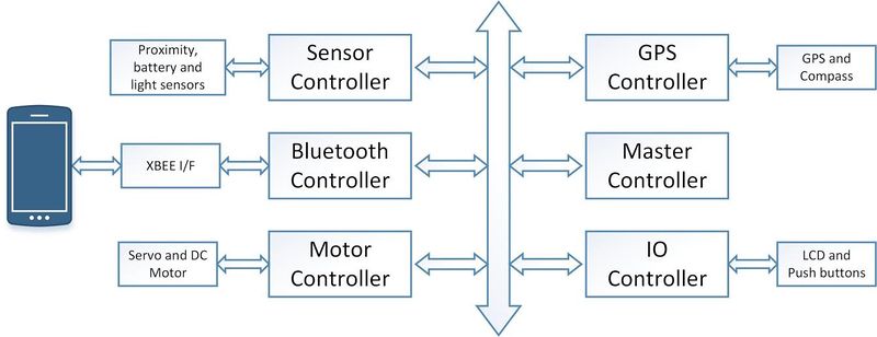
This project is aimed at developing a 1/10 RC car with a self-driving capability based on controller interaction over the CAN (Controller Area Network) bus. With the advent of driverless cars, we felt the need to develop a scaled-down version that can maneuver itself through co-ordinates fed by Google maps and correct its course when it sees an obstacle. To achieve this objective, we plan to integrate 6 controllers dedicated to specific roles that can pass messages over a common CAN communication bus. In addition, the prototype would involve an Android mobile application for data monitoring and controlling purpose to keep a track of the car remotely and feed it the required checkpoints to reach its destination. The car would comprise of three modes of operation namely; home, map and free run. In the home mode, the car would be guided to its home destination (which is preset to Boccardo Business center) from its current location. In the map mode, the user can feed in the desired destination through the google maps interface which the car would follow based on the co-ordinates and heading provided by its GPS and compass respectively. The free run mode will convert the mobile phone into a remote device capable of controlling the speed and direction of the car based on the accelerometer and gyroscope enabled on the device. In this way, the user can take control of the car at any given time. Below is the high-level block diagram of the entire system.
Startup
The following series of events would take place when the car is powered on:
- The GPS would wait for a satellite fix of at least 3 satellites, which would relay the information to the Android device through its controller over the CAN bus.
- If the user selects the Map mode, he would be required to enter the co-ordinates of the destination visually by dropping a marker on the map.
- The app would compute the checkpoints and distance and feed the information to the on-board communication controller.
- The first checkpoint is sent to the GPS and master controller, which would co-ordinate the events for the motor and sensor controllers.
- Any obstacle detected by the ultrasonic sensors would override the current path and try to avoid the obstacle.
- The master controller would compute the course correction and reconfigure the required controllers once the car has passed the obstacle.
- The IO controller is responsible for monitoring the data on the CAN bus and displaying the information on the mounted LCD panel. The light and battery sensors are also connected to the IO controller, which automatically turn on the headlights and monitor the battery health respectively.
- Start/Stop triggers can be given to the car remotely using the mobile application as well as from the on-board LCD.
- Once the car reaches the first checkpoint, it will request for the second one from the communication controller and pass it over to the master. In this way, the process continues till the car reaches the destination.
- Home mode operates in a similar way but with a fixed destination and the free run mode is pretty much self-explanatory
Highlights
- Self-Navigation with Obstacle avoidance on all sides on the car.
- Google maps interface for location monitoring and destination setting along with checkpoint computation.
- Three modes of operation – Home, Map and Free run.
- Three choices of speed – Slow (8 mph), Normal (10 mph) and Turbo (12 mph).
- Automatic checkpoint detection and request for checkpoint system.
- Headlights using lights sensors and brake lights on the tail.
- Battery health monitoring.
- Visual picturization of sensor data relative the car on the android application.
- Speed gauge and compass needle for easier visualization on the application.
- Kill switch for instant power off.
- Free run mode for remotely controlling the car.
Team Members & Responsibilities
- Sensor Controller:
- Motor Controller
- I/O Unit:
- Communication Bridge + Android:
- Geographical Controller:
- Master Controller:
Parts List & Cost
| S.R. | Description | Manufacturer | Part Number | Qty | Total Cost |
|---|---|---|---|---|---|
| 1 | SJOne Board | - | - | 6 | $480.00 |
| 2 | RC Car | Traxxas | - | 1 | $240.00 |
| 3 | Ultrasonic Sensor | Parallax | 28015 | 3 | $69.00 |
| 4 | ADC Sensor | Maxbotix | MB1000 | 1 | $29.00 |
| 5 | LDR | - | - | 1 | $1.00 |
| 6 | Battery Health Monitoring Resistors | - | - | 2 | $2.00 |
| 7 | IR Sensor (Used as Speed Encoder) | - | - | 1 | $15.00 |
| 8 | GLCD with Touchscreen | 4D Systems | uLCD-32PTU | 1 | $106.00 |
| 9 | Tact Switches | - | - | 4 | $2.00 |
| 10 | LEDs with Holders | - | - | 4 | $2.00 |
| 11 | XBee Module | Digi | XBee Series1 | 2 | $40.00 |
| 12 | Bluetooth Module | Microchip | RN42XVP-I/RM | 1 | $20.00 |
| 13 | GPS Module | Sparkfun | GPS-11058 | 1 | $49.95 |
| 14 | Compass Module | Adafruit | HMC5883L | 1 | $9.95.00 |
| 15 | CAN Transceiver (Free Samples) | Microchip | MCP2551 | 6 | $0.00 |
| 16 | Linear Voltage Regulator (Free Sample) | LT | LT1083-5 | 1 | $0.00 |
| 17 | Miscellaneous | - | - | - | $20.00 |
| Total (Excluding Shipping and Taxes | $0000.00 |
Design & Implementation
CAN 11-bit ID Format
| MSG | DST | SRC |
|---|---|---|
| 5 bits (11-6) | 3 bits (5-3) | 3 bits (2-0) |
Controller ID Table
| Controller ID | Controller Type |
|---|---|
| 001 | Motor Controller |
| 010 | Master Controller |
| 011 | Sensor Controller |
| 100 | GEO Controller |
| 110 | Communication Bridge + Android Controller |
| 111 | I/O Controller |
Controller Communication Table
| S.R. | Message Number | Destination | Message Name (MSG_FUNCTION) | Data Layout of Data Sent over CAN (byte[0] = total number of data bytes) |
|---|---|---|---|---|
| 1 | 0x042 | All | RESET |
NO DATA |
| 2 | 0x082 | All | POWERUP_SYN |
NO DATA |
| 3 | 0x102 | All | POWERUP_ACK |
Msg1 : byte[1] : (uint8_t) version Msg1 : byte[2-3] : (uint16_t) year Msg1 : byte[4] : (uint8_t) month Msg1 : byte[5] : (uint8_t) date Msg1 : byte[6] : (uint8_t) dayofweek Msg1 : byte[7] : (uint8_t) hour Msg2 : byte[1] : (uint8_t) minute Msg2 : byte[2] : (uint8_t) second |
| 4 | 0x142 | All | HEARTBEAT |
Msg1 : byte[1-2] : (uint16_t) rx_count Msg1 : byte[3-4] : (uint16_t) rx_bytes Msg1 : byte[5-6] : (uint16_t) tx_count Msg1 : byte[7] : (uint16_t) tx_bytes Msg2 : byte[1] : (uint16_t) tx_bytes |
| 5 | 0x3CA | Motor | SPEED_DIR_COMMAND |
Msg1 : byte[1] : (uint8_t) speed Msg1 : byte[2] : (uint8_t) direction Msg1 : byte[3] : (uint8_t) brake |
| S.R. | Message Number | Destination | Message Name (MSG_FUNCTION) | Data Layout of Data Sent over CAN (byte[0] = total number of data bytes) |
|---|---|---|---|---|
| 1 | 0x0D1 | Master | POWERUP_SYN_ACK |
Msg1 : byte[1] : (uint8_t) version |
| 2 | 0x191 | Master | HEARTBEAT_ACK |
Msg1 : byte[1-2] : (uint16_t) rx_count Msg1 : byte[3-4] : (uint16_t) rx_bytes Msg1 : byte[5-6] : (uint16_t) tx_count Msg1 : byte[7] : (uint16_t) tx_bytes Msg2 : byte[1] : (uint16_t) tx_bytes |
| 3 | 0x341 | Master, I/O and Communication Bridge | SPEED_ENCODER_DATA |
Msg1 : byte[1] : (uint8_t) speed Msg1 : byte[2] : (uint8_t) dir Msg1 : byte[3] : (uint8_t) brake |
| S.R. | Message Number | Destination | Message Name (MSG_FUNCTION) | Data Layout of Data Sent over CAN (byte[0] = total number of data bytes) |
|---|---|---|---|---|
| 1 | 0x0D4 | Master | POWERUP_SYN_ACK |
Msg1 : byte[1] : (uint8_t) version |
| 2 | 0x194 | Master | HEARTBEAT_ACK |
Msg1 : byte[1-2] : (uint16_t) rx_count Msg1 : byte[3-4] : (uint16_t) rx_bytes Msg1 : byte[5-6] : (uint16_t) tx_count Msg1 : byte[7] : (uint16_t) tx_bytes Msg2 : byte[1] : (uint16_t) tx_bytes |
| 3 | 0x384 | Master, I/O and Communication | GEO_HEADING_DATA |
Msg1 : byte[1] : (uint8_t) current_angle Msg1 : byte[2] : (uint8_t) desired_angle Msg1 : byte[3] : (uint8_t) destination_reached Msg1 : byte[4] : (uint8_t) is_valid |
| 4 | 0x484 | I/O and Communication Bridge | GEO_LOCATION_DATA |
Msg1 : byte[1-4] : (float) latitude Msg1 : byte[5-7] : (float) longitude Msg2 : byte[1] : (float) longitude Msg2 : byte[2-3] : (uint16_t) dist_to_final_destination Msg2 : byte[4-5] : (uint16_t) dist_to_next_checkpoint Msg2 : byte[6] : (uint8_t) is_valid |
| 5 | 0x2AC | Communication Bridge | CHECKPOINT_REQUEST |
Msg1 : byte[1] : (uint8_t) checkpoint_num |
| S.R. | Message Number | Destination | Message Name (MSG_FUNCTION) | Data Layout of Data Sent over CAN (byte[0] = total number of data bytes) |
|---|---|---|---|---|
| 1 | 0x0D5 | Master | POWERUP_SYN_ACK |
Msg1 : byte[1] : (uint8_t) version |
| 2 | 0x195 | Master | HEARTBEAT_ACK |
Msg1 : byte[1-2] : (uint16_t) rx_count Msg1 : byte[3-4] : (uint16_t) rx_bytes Msg1 : byte[5-6] : (uint16_t) tx_count Msg1 : byte[7] : (uint16_t) tx_bytes Msg2 : byte[1] : (uint16_t) tx_bytes |
| 3 | 0x1D5 | Master and I/O | CAR_PAUSE |
NO DATA |
| 4 | 0x215 | Master and I/O | CAR_RESUME |
NO DATA |
| 5 | 0x425 | Geographical | CHECKPOINT_DATA |
Msg1 : byte[1-4] : (float) latitude Msg1 : byte[5-7] : (float) longitude Msg2 : byte[1] : (float) longitude Msg2 : byte[2-3] : (uint16_t) total_distance Msg2 : byte[4] : (uint8_t) checkpoint_num Msg2 : byte[5] : (uint8_t) is_new_route Msg2 : byte[6] : (uint8_t) is_final_checkpoint |
| 6 | 0x2C5 | Master, I/O, Communication Bridge and Motor | DRIVE_MODE |
Msg1 : byte[1] : (uint8_t) mode |
| 7 | 0x255 | Master | FREE_RUN_DIR |
Msg1 : byte[1] : (uint8_t) speed Msg1 : byte[2] : (uint8_t) turn Msg1 : byte[3] : (uint8_t) direction |
| S.R. | Message Number | Destination | Message Name (MSG_FUNCTION) | Data Layout of Data Sent over CAN (byte[0] = total number of data bytes) |
|---|---|---|---|---|
| 1 | 0x0D3 | Master | POWERUP_SYN_ACK |
Msg1 : byte[1] : (uint8_t) version |
| 2 | 0x193 | Master | HEARTBEAT_ACK |
Msg1 : byte[1-2] : (uint16_t) rx_count Msg1 : byte[3-4] : (uint16_t) rx_bytes Msg1 : byte[5-6] : (uint16_t) tx_count Msg1 : byte[7] : (uint16_t) tx_bytes Msg2 : byte[1] : (uint16_t) tx_bytes |
| 3 | 0x303 | Master, I/O and Communication Bridge | DIST_SENSOR_DATA |
Msg1 : byte[1] : (uint8t) left Msg1 : byte[2] : (uint8t) middle Msg1 : byte[3] : (uint8t) right Msg1 : byte[4] : (uint8t) back |
| 4 | 0x443 | I/O and Communication Bridge | OTHER_SENSOR_DATA |
Msg1 : byte[1] : (uint8t) battery Msg1 : byte[2] : (uint8t) light |
| S.R. | Message Number | Destination | Message Name (MSG_FUNCTION) | Data Layout of Data Sent over CAN (byte[0] = total number of data bytes) |
|---|---|---|---|---|
| 1 | 0x056 | Master | RESET |
NO DATA |
| 2 | 0x0D6 | Master | POWERUP_SYN_ACK |
Msg1 : byte[1] : (uint8_t) version |
| 3 | 0x196 | Master | HEARTBEAT_ACK |
Msg1 : byte[1-2] : (uint16_t) rx_count Msg1 : byte[3-4] : (uint16_t) rx_bytes Msg1 : byte[5-6] : (uint16_t) tx_count Msg1 : byte[7] : (uint16_t) tx_bytes Msg2 : byte[1] : (uint16_t) tx_bytes |
| 4 | 0x1D4 | Master and I/O | CAR_PAUSE |
NO DATA |
| 5 | 0x214 | Master and I/O | CAR_RESUME |
NO DATA |
| 6 | 0x2C4 | Master, I/O and Motor | DRIVE_MODE |
Msg1 : byte[1] : (uint8_t) mode |
Power Circuit
Sensor Controller
Motor Controller
I/O Controller
Communication Bridge + Android Controller
Introduction
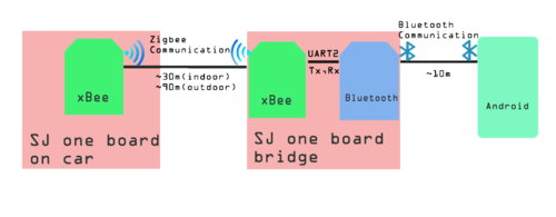
The communication bridge is a connection between Android application and other controllers on the RC car. The Android application is written in Java and there are xBee(ZigBee) chip sets along with Bluetooth as a bridge connection. The major functions of the bridge is
- Allow a user to see sensor values, car speed, etc.
- Allow a user to select a destination from Google Earth.
Modules
1. xBee Module:
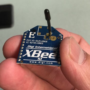
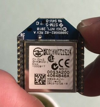
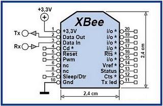
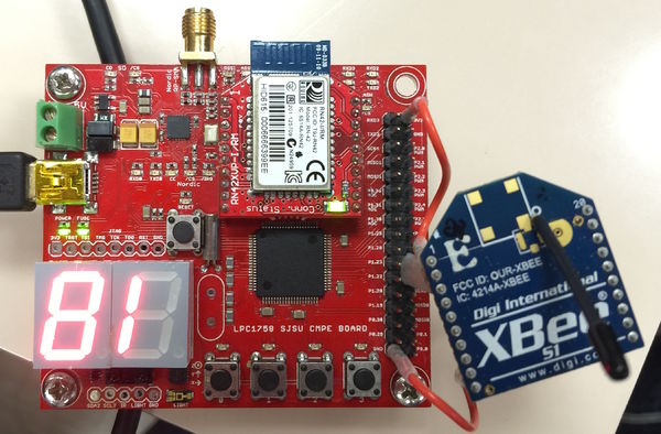
The following pictures shown the chip set of xBee which is using zigbee to communicate with each other:
|
Features:
|
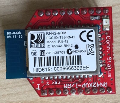
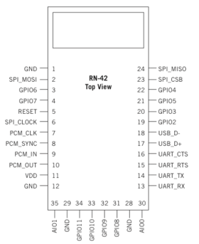
2. Bluetooth Module (RN-421):
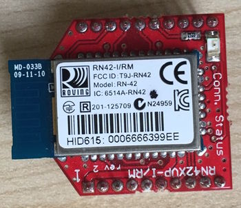
The following picture is the Bluetooth module RN-42I:
Features:
- Fully qualified Bluetooth version 2.1 module, support version 2.1+Enhanced Data Rate (EDR)
- Backwards compatible with Bluetooth version 2.0, 1.2 and 1.1.
- Low power (26uA sleep, 3mA connected, 30mA transmit)
- UART (SPP or HCL) and USB (HCI only) data connection interfaces.
- Sustained SPP data rates: 240 Kbps (slave), 300Kbps (master)
- HCI data rates: 1.5 Mbps sustained, 2.0Mbps burst in HCI mode
- Bluetooth SIG certified
- Castellated SMT pads for easy and reliable PCB mounting
- Certifications: FCC, ICS, CE
Interface
1. xBee:
Communication setup:
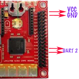
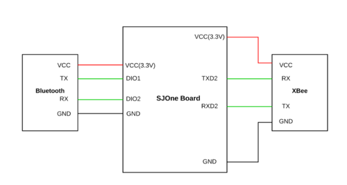
Since we are not connecting the xBee directly to our computer to work on the configuration and we have to connect it through using the SJ One board with UART communication pins. Thus, we have to initially set the baud rate at 115200. On xBee chip set, there are 20 pins including VCC and GND. In our design of the communication bridge, we just need four of them including VCC (Pin1), GND(Pin10), Data Out(Pin2), and Data In (Pin3). For xBee chip set connected with Bluetooth module, VCC is connected to SJ One board VCC out as well as GND. For Data out on xBee, it is connected UART 2 Rx(Pin49) and Data in connected to UART Tx(Pin50). For xBee chip set connected to car SJ One board, we can directly place it on xBee connect pins on SJ One board.
Pairing:
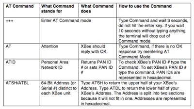
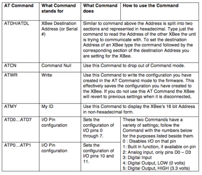
In order to let the xBee pair to communicate to each other, we have to set both xBee chip sets have the same PAN ID. The xBee has factory default setting that we just have to input default commands for viewing or changing the setting on chips. Some of major commands show as following:
Since we are using SJ One board to connect with the xBee chip sets, so we have decided to implement commands inside the FreeRTOS program. In the implementation, we have included the following logic to pair the xBee chip sets. Steps of pairing xBee chip set:
- Checking both xBee chip sets are working with “AT” command and it will return “OK” for working
- Checking and changing PAN ID on either one xBee to match with another and the PAN ID are usually 4 digits numbers. “ATID” is the command to check and change the ID
- Checking and changing the destination address for both xBee chip sets. The address of chip sets are printed on the bottom of the xBee.
2. Bridge between xBee and bluetooth:
Since xBee cannot communicate with regular android cell phone, we would need one device/module that common accepted for both configurations. Bluetooth is one of the best devices for this purpose. In order to create a platform for these two device (Bluetooth and xBee), SJ One board has been used as the medium to make communication bridge them. On the SJ One board, we have chosen UART 2 as communication connector among UART 2 or UART 3. There is no logic stored on the SJ One board but the initialization for the UART port. The logic for the communication for Bluetooth and xBee module is simple. The baud rate has to set to 115200 for both module Tx of Bluetooth has to connect with Tx of xBee while Rx of Bluetooth has to connect with Rx of xBee. Besides, both Vcc(3.3V) and Ground of Bluetooth module and xBee module are connected to the Vcc and ground on SJ One board respectively.
3. Bluetooth:
Bluetooth module is providing a connection for Android device and xBee. There is no initialization such as initializing Pan ID on xBee on the Bluetooth module but the Android device side. For the first time connection between Android device and the Bluetooth module, we need to pair them. In the Bluetooth device searching section (Setting -> Bluetooth) of the Android device, we can see the Bluetooth module name e.g.RNBT-99EE. In order to pair them, there is a default pass code (0000 or 1234) to enter from the Android device.
Android Application
The Android Application is connected to the car through the Bluetooth-xbee interface. The first point of contact for the application is the Bluetooth module for which a separate class was written which connects using sockets based on the UUID (Universally Unique Identifier) and pairing history of the device running the code.
| Module Name | S.R. | Test Case | Test Description | Result |
|---|---|---|---|---|
| Sensor | 1 | - | - | - |
| 2 | - | - | - | |
| 3 | - | - | - | |
| Motor | 1 | - | - | - |
| 2 | - | - | - | |
| 3 | - | - | - | |
| I/O | 1 | - | - | - |
| 2 | - | - | - | |
| 3 | - | - | - | |
| Communication Bridge+ Android |
1 | - | - | - |
| 2 | - | - | - | |
| 3 | - | - | - | |
| Geographical | 1 | - | - | - |
| 2 | - | - | - | |
| 3 | - | - | - | |
| Master | 1 | - | - | - |
| 2 | - | - | - | |
| 3 | - | - | - |
Schedule
| Sl. No | Start Date | End Date | Task | Status | Actual Completion Date |
|---|---|---|---|---|---|
| 1 | 09/14/2014 | 09/20/2014 | Understanding the logic of sensors to be used | Completed | 09/20/2014 |
| 2 | 09/21/2014 | 10/04/2014 | Writing the codes for the different types of sensors | Completed | 10/04/2014 |
| 3 | 10/05/2014 | 10/11/2014 | Testing the different sensors for accuracy and placing the order for the one we have selected. | Completed | 10/11/2014 |
| 4 | 10/12/2014 | 10/25/2014 | Build CAN transceiver and send data to the Master Board | Completed | 10/25/2014 |
| 5 | 10/26/2014 | 11/01/2014 | Place all the sensors on car and test for obstacle avoidance | Completed | 10/28/2014 |
| 6 | 11/02/2014 | 11/14/2014 | Work on light and tilt sensors | Completed | 11/04/2014 |
| 7 | 11/15/2014 | 12/09/2014 | Final testing and debugging | Completed | 12/19/2014 |
| Sl. No | Start Date | End Date | Task | Status | Actual Completion Date |
|---|---|---|---|---|---|
| 1 | 09/14/2014 | 09/20/2014 | Understand the logic of Motor Controller present in the RC Car | Completed | 09/20/2014 |
| 2 | 09/21/2014 | 09/27/2014 | Replace on-board controller with SJSU One board | Completed | 09/22/2014 |
| 3 | 09/28/2014 | 10/04/2014 | Drive the DC motor with SJSU One board at different Duty Cycles | Completed | 09/30/2014 |
| 4 | 10/05/2014 | 10/11/2014 | Test the Servo and DC motor together for moving forward and taking turns | Completed | 10/09/2014 |
| 5 | 10/12/2014 | 10/18/2014 | Build CAN Transceiver and move the car as per the CAN message received | Completed | 10/13/2014 |
| 6 | 10/19/2014 | 10/25/2014 | Make arrangement for CAN subscription task | Completed | 10/25/2014 |
| 7 | 10/26/2014 | 11/01/2014 | Interface encoder and calculate the actual speed at which car is running | Completed | 10/28/2014 |
| 8 | 11/02/2014 | 11/08/2014 | Make compensation algorithm and make car to move at desired speed | Completed | 11/04/2014 |
| 9 | 11/09/2014 | 12/09/2014 | Final testing and debugging | Completed | 12/19/2014 |
| Sl. No | Start Date | End Date | Task | Status | Actual Completion Date |
|---|---|---|---|---|---|
| 1 | 09/14/2014 | 09/20/2014 | Search and order GLCD module with touch screen, LEDs for headlights | Completed | 09/20/2014 |
| 2 | 09/21/2014 | 10/04/2014 | Study of GLCD data frame formats and design GUI | Completed | 10/03/2014 |
| 3 | 10/05/2014 | 10/11/2014 | Development of GLCD functions including touchscreen handler | Completed | 10/11/2014 |
| 4 | 10/12/2014 | 10/25/2014 | Setup CAN subscription tasks for communication with Master controller | Completed | 10/27/2014 |
| 5 | 10/26/2014 | 11/01/2014 | Develop hardware and code for automatic headlight control. | Completed | 11/01/2014 |
| 6 | 11/02/2014 | 11/14/2014 | Build hardware for switches and write interrupt handlers for the same | Completed | 11/07/2014 |
| 7 | 11/15/2014 | 12/09/2014 | Mount GLCD, headlights, switches on car and final testing | Completed | 12/19/2014 |
| Sl. No | Start Date | End Date | Task | Status | Actual Completion Date |
|---|---|---|---|---|---|
| 1 | 09/14/2014 | 09/20/2014 | Google maps API research | Completed | 09/20/2014 |
| 2 | 09/21/2014 | 10/04/2014 | Mock locations on Google maps and simulate co-ordinates w/o gps | Completed | 10/04/2014 |
| 3 | 10/05/2014 | 10/11/2014 | Two way Bluetooth communication and setup RTOS tasks | Completed | 10/11/2014 |
| 4 | 10/12/2014 | 10/25/2014 | Raw GUI for app and setup CAN tasks for Start and Stop commands | Completed | 10/25/2014 |
| 5 | 10/26/2014 | 11/09/2014 | Integration with GEO module and queue for each subscribed service | Completed | 11/09/2014 |
| 6 | 11/10/2014 | 11/16/2014 | Incorporate all essential services into Android app and test for response | Completed | 11/16/2014 |
| 7 | 11/16/2014 | 11/23/2014 | Final setup and changes for all the CAN tasks along with XBee interfacing | Completed | 11/23/2014 |
| 8 | 11/24/2014 | 12/01/2014 | Testing with GEO module with real-time co-ordinates and plotting way points onto Maps | Completed | 12/01/2014 |
| 9 | 12/02/2014 | 12/09/2014 | Final Testing and verification of all components on the main field | Completed | 12/19/2014 |
| Sl. No | Start Date | End Date | Task | Status | Actual Completion Date |
|---|---|---|---|---|---|
| 1 | 09/7/2014 | 09/14/2014 | Market research for GPS and Compass Modules | Completed | 09/14/2014 |
| 2 | 09/14/2014 | 09/21/2014 | Place order / receive the modules | Completed | 09/20/2014 |
| 3 | 09/21/2014 | 09/28/2014 | Interface GPS with SJ -One board via UART | Completed | 09/26/2014 |
| 4 | 09/28/2014 | 10/05/2014 | Interface Compass with SJ-One Board via I2C | Completed | 10/03/2014 |
| 5 | 10/05/2014 | 10/12/2014 | Parsing the GPS data stream | Completed | 10/11/2014 |
| 6 | 10/12/2014 | 10/19/2014 | Calibration and testing of compass | Completed | 10/13/2014 |
| 7 | 10/12/2014 | 10/19/2014 | Decide CAN message ID’s and message formats | Completed | 10/28/2014 |
| 8 | 10/19/2014 | 10/26/2014 | Combining UART and GPS parsing. Create task for GPS | Completed | 10/25/2014 |
| 9 | 10/19/2014 | 10/26/2014 | Combining compass calibration and i2c interface. Create task for Compass | Completed | 10/25/2014 |
| 10 | 10/26/2014 | 11/02/2014 | Distance to Destination Calculation and Algorithm | Completed | 11/02/2014 |
| 11 | 11/03/2014 | 11/10/2014 | Basic CAN communication with Master, IO and Android | Completed | 11/10/2014 |
| 12 | 11/10/2014 | 11/17/2014 | Synchronization and Data Integrity (Semaphores/Mutex/Critical Section) | Completed | 11/17/2014 |
| 13 | 11/18/2014 | 11/25/2014 | Final Integration of CAN Framework and Implementation of CAN communication with other modules | Completed | 11/25/2014 |
| 14 | 11/26/2014 | 12/09/2014 | Testing and debugging on car (Re-Calibration/Bug Fixes) | Completed | 12/19/2014 |
| Sl. No | Start Date | End Date | Task | Status | Actual Completion Date |
|---|---|---|---|---|---|
| 1 | 09/7/2014 | 09/13/2014 | Understanding CAN Bus and API's | Completed | 09/13/2014 |
| 2 | 09/14/2014 | 09/20/2014 | Deciding System Flow | Completed | 09/20/2014 |
| 3 | 09/21/2014 | 09/27/2014 | Deciding MSG id's for all devices | Completed | 10/27/2014 |
| 4 | 09/28/2014 | 10/11/2014 | Testing Subscription between 2 devices | Completed | 10/4/2014 |
| 5 | 09/28/2014 | 10/11/2014 | Making CAN bus hardware to interface all SJOne boards | Completed | 10/11/2014 |
| 6 | 09/28/2014 | 10/11/2014 | Testing subscription and time sync between all devices | Completed | 10/11/2014 |
| 7 | 10/12/2014 | 10/18/2014 | Reading sensor data from boards at the subscription rate | Completed | 10/26/2014 |
| 8 | 10/19/2014 | 11/1/2014 | Algorithm for obstacle avoidance | Completed | 10/27/2014 |
| 9 | 11/2/2014 | 11/15/2014 | Algorithm for GPS based navigation | Completed | 11/15/2014 |
| 10 | 11/16/2014 | 11/22/2014 | Initial testing and tweaking of the car | Completed | 11/22/2014 |
| 11 | 11/23/2014 | 12/9/2014 | Final Testing! Showdown time! | Completed | 12/19/2014 |
Challenges and Learning
Future Enhancement
Conclusion
Project Video
Project Source Code
References
Acknowledgement
The hardware components were made available from Amazon, Sparkfun, Adafruit, HSC, Excess Solutions. Thanks to Preetpal Kang for providing right guidance for our project.
References Used
- LPC_USER_MANUAL
- Ultrasonic Sensor
- ADC Sensor
- GLCD with Touchscreen
- XBee Module
- Bluetooth Module
- GPS Module
- Compass Module
- CAN Transceiver
- Linear Voltage Regulator
- Socialledge Embedded Systems Wiki
- Preetpal Kang, Lecture notes of CMPE 243, Computer Engineering, Charles W. Davidson College of Engineering, San Jose State University, Aug-Dec 2014.
- en.wikipedia.org/
