F14: Team2-Self Driving Car - AUG
Contents
- 1 Self Driving Car
- 2 Abstract
- 3 Objective and Scope
- 4 Team Members & Responsibilities
- 5 Introduction
- 6 Schedule
- 7 Parts List & Cost
- 8 Backup Parts & cost
- 9 Design & Implementation
- 9.1 Controller Communication Table
- 9.2 Master controller
- 9.3 Hardware Interface
- 9.4 Software Design and Implementation
- 9.5 Android and Bridge
- 9.6 Sensor Controller
- 9.7 I/O Unit
- 9.8 Geographical Controller
- 9.9 GPS Module Features
- 9.10 HMC-6352 Digital Compass Features
- 9.11 Hardware Design
- 9.12 Hardware Pin Diagram
- 9.13 Software Design
- 10 Testing & Technical Challenges
- 11 Challenges and Learning
- 12 Future Enhancement
- 13 Conclusion
- 14 Project Video
- 15 Project Source Code
- 16 References
Self Driving Car
Abstract
This report focus on creating self navigating RC car. The project is implemented using SJOne board which has Cortex-M3 LPC1758 controllers on it. It uses CAN bus protocol to communicate between six different nodes( SJOne board ) which are connected through CAN bus. Various modules are Master controller, motor controller, Geo module, sensor controller, Display controller and android bluetooth bridge. The navigation direction is being provided by GPS android app over bluetooth.
Based on the source and destination coordinate values, Geo controller computes the difference between car heading (current direction) and bearing (required direction). Based on the difference value, master drives the motor controller to the destination. Intermittently any obstacles are avoided based on the sensor controller data indicating obstacle.
Objective and Scope
Objective
The objective of this project is to demonstrate and implement the learning of CMPE243 Embedded System class. Other objective was to prepare students according to industry standard by facilitating industry like training. To accomplish this, a team of 16 person were divided into six sub teams which were responsible for individual modules. It also facilitates the learning of GIT Lab repository for code version control and synchronization.
The technical objective was to learn and implement various hardware/software modules like CAN Bus, GPS module, Compass module, Display , Sensors, power unit and Bluetooth module. It also facilitates implementation of various communicating protocols like GPIO, UART, I2C, SPI , PWM , CAN. In nutshell the real objective was to prepare engineers for real life challenges.
Scope
The scope of this project is limited to developing self navigating car for education use only which should be tested under proper supervision.
Team Members & Responsibilities
- Sensor Controller
- Amey Patil
- Sujith Durgad
- Arvind Allawadi
- Motor Controller and Power
- Digvijay Patil (Master Documenation)
- Rohan Jani
- Mahesh Chudasama
- Display
- Mradula Nayak
- Karthik Govindaswamy
- Communication Bridge + Android
- Siddhata Patil
- Mohammed Raashid Kheruwala
- Huzefa Siyamwala
- Geographical Controller
- Yash Parulekar
- Ajinkya Khasnis
- Harsh Lavingia
- Anand Dumbre
- Master Controller
- Pradyumna Upadhya
Introduction
Overall Algorithm :
1. GPS co-ordinates is sent from Andriod app to Andriod controller through bluetooth interace.
2. Andriod Controller sends these co-ordinates to GPS+Compass controller
3. START command is sent from Andriod app to Andriod controller, which in turn sends START can command to Master controller.
4. Master controller sends START can command to Motor, Sensor, IO, GPS+Compass controllers.
5 When controllers get START command they subscribe to other boards at either 1,5,10,20,50Hz.
6. All the boards start calculating required can message values and publish subscribed messages data at subscribed frequency.
7. All the boards receive the new published data.
8. Steps 6 to 8 continue untill STOP command is sent from Master(which in turn receive it from Andriod app)or destination reached message is got from GPS+Compass controller to master.
9. Master subscribes to Sensor and GPS+Compass controllers to keep getting new data at any of above mentioned frequency.
10. Motor subscribes to Master to get car movement direction,speed message at any of above mentioned frequency.
11. IO subscribes to Master, Motor, Sensor and GPS+Compass controllers to get display data.
12. GPS+Compass controller calculates current direction and required direction for given moment and sends this data to Master. Master checks sensor values and if there are no obstacle moves as per required direction given by GPS+Compass. If there are obstacles then it moves to avoid the given obstacle.
13. Steps 12 keeps repeating untill required co-ordinates are reached.
Schedule
Common Schedule
| Sl. No | Start Date | End Date | Task | Status | Actual Completion Date |
|---|---|---|---|---|---|
| 1 | 9/16/2014 | 10/7/2014 | Finish Ordering project hardware parts | Completed. | 11/10/2014 |
| 2 | 10/5/2014 | 10/21/2014 | Fine tune subscriber code | Completed | 10/28/2014 |
| 3 | 10/7/2014 | 10/21/2014 | Finish Development of CAN Transceiver boards | Completed | 10/25/2014 |
| 4 | 10/5/2014 | 11/4/2014 | Sub teams finalize and implement dependency code(atleast single API per team) | Completed | 10/28/2014 |
| 5 | 10/5/2014 | 10/28/2014 | Finish hardware | Completed | 10/27/2014 |
| 6 | 10/28/2014 | 12/2/2014 | Start integration and testing. | Scheduled | 12/19/2014 |
Master Team Schedule
| Sl. No | Start Date | End Date | Task | Status | Actual Completion Date |
|---|---|---|---|---|---|
| 1 | 9/30/2014 | 10/21/2014 | Fine tune subscriber code and finalize CAN apis required from other boards | Completed | Completed on 10/21/2014 |
| 2 | 10/5/2014 | 10/21/2014 | Fine tune subscriber code | Completed | Completed on 10/27/2014 |
| 3 | 10/5/2014 | 10/21/2014 | Develop CAN Transceiver Board | Completed | Completed by 10/19/2014 |
| 4 | 10/5/2014 | 11/4/2014 | Implement API co-ordination logic and test with other boards APIs | Completed | Completed by 11/20/2014 |
| 5 | 10/21/2014 | 10/28/2014 | Test hardware with master code and motor code. | 10/26/2014 | Master and motor has been integrated. |
| 6 | 10/21/2014 | 11/4/2014 | Integrate master with motor and sensor. | Completed | |
| 7 | 10/28/2014 | 11/11/2014 | Integrate master ,motor,sensor with andriod. | Completed | 11/10/2014 |
| 8 | 10/28/2014 | 11/11/2014 | Integrate master with display. | Completed | 11/10/2014 |
| 9 | 10/4/2014 | 11/11/2014 | Integrate master with compass and gps. | Completed | 11/20/2014 |
| 10 | 11/4/2014 | 11/18/2014 | Fix integration bugs and fine tune boards initialization and communication. | Completed | 11/15/2014 |
| 11 | 11/11/2014 | 11/28/2014 | Implement car movement logic as per GPS/COMPASS/Sensor data. | Ongoing | 12/19/2014 |
| 12 | 11/28/2014 | 12/10/2014 | Test hardware/software to remove bugs and fine tune algorithm. | Ongoing | 12/19/2014 |
GEO Team Schedule
| Sl. No | Start Date | End Date | Task | Status | Actual Completion Date |
|---|---|---|---|---|---|
| 1 | 9/16/2014 | 9/23/2014 | Decided and then ordered GPS modem Received Compass module |
Completed | 9/23/2014 |
| 2 | 9/23/2014 | 9/30/2014 | Acquired GPS modem Interface Compass with SJOne Board via I2C |
Completed | 9/30/2014 |
| 3 | 9/30/2014 | 10/7/2014 | Designing GPS driver Test code to get compass heading information |
OnGoing Completed |
TBD |
| 4 | 10/7/2014 | 10/21/2014 | Integration of GPS with the main board CAN RX task and subscription handling |
In Progress | TBD |
| 5 | 10/21/2014 | 11/04/2014 | Test communication with the Master Determine final heading using GPS location and compass reading |
Scheduled | TBD |
| 6 | 11/04/2014 | 11/18/2014 | Test and debug, Make necessary changes in the driver Compass Calibration |
Scheduled | TBD |
Motor Team Schedule
| Sl. No | Start Date | End Date | Task | Status | Actual Completion Date |
|---|---|---|---|---|---|
| 1 | 9/30/2014 | 10/7/2014 | Understand the SERVO and DC motor controller signals | Completed | 10/4/2014 |
| 2 | 10/4/2014 | 10/11/2014 | Interface SJSU one board to SERVO and DC motor controller | Completed | 10/10/2014 |
| 3 | 10/7/2014 | 10/18/2014 | Develop CAN transceiver boards | Completed | 10/12/2014 |
| 4 | 10/12/2014 | 10/26/2014 | Design and Develop unified power distribution circuit and hardware structure for RC car | Completed | 10/25/2014 |
| 5 | 10/19/2014 | 11/03/2014 | Interface motor SJSU board with master SJSU board for motion tuning | Completed | 11/03/2014 |
| 6 | 10/26/2014 | 11/07/2014 | Redesign mechanical structure and fix wiring issue | Completed | 11/08/2014 |
| 7 | 10/19/2014 | 11/07/2014 | Work on shaft encoder for motor speed feedback | Completed | 11/14/2014 |
| 8 | 11/01/2014 | 11/11/2014 | Work with other teams to establish reliable CAN communication. | Completed | 11/11/2014 |
| 9 | 11/07/2014 | 11/30/2014 | Fine tuning of turning curves, jerks, acceleration and deceleration algorithm. | Completed | 12/12/2014 |
I/O Team Schedule
| Sl. No | Start Date | End Date | Task | Status | Actual Completion Date |
|---|---|---|---|---|---|
| 1 | 9/16/2014 | 9/23/2014 | Decided and then ordered display module | Completed | 9/23/2014 |
| 2 | 9/24/2014 | 10/7/2014 | Setting up the GIT | Completed | 10/14/2014 |
| 3 | 10/7/2014 | 10/14/2014 | Basic display on LCD with UART interface | Completed | 10/23/2014 |
| 4 | 10/14/2014 | 10/28/2014 | CAN communication between Master and I/O | Completed | 10/28/2014 |
| 5 | 10/28/2014 | 10/31/2014 | CAN communication between I/O and sensor | Completed | 11/02/2014 |
| 6 | 10/31/2014 | 11/4/2014 | CAN communication between I/O and GPS | Completed | 11/02/2014 |
| 7 | 11/5/2014 | 11/9/2014 | Logic for No. of CAN messages/sec, LED's for Start, CAN Tx,CAN Rx | Completed | 11/18/2014 |
| 8 | 11/9/2014 | 11/15/2014 | Mount LCD on board on CAR and Final testing | Completed | 11/30/2014 |
Sensor Controller
| Sl. No | Start Date | End Date | Task | Status | Actual Completion Date |
|---|---|---|---|---|---|
| 1 | 10/3/2014 | 10/10/2014 | Developing a Test code for sensors | Completed | 10/14/2014 |
| 2 | 10/10/2014 | 10/17/2014 | Finalizing on the sensors | Completed | 10/14/2014 |
| 3 | 10/17/2014 | 10/24/2014 | Transfer of sensor data via can bus to master | Completed | 10/21/2014 |
| 4 | 10/24/2014 | 10/30/2014 | Implementation with multiple sensors | Completed | 10/30/2014 |
| 5 | 10/30/2014 | 11/24/2014 | Testing the implementation for multiple sensors and debugging the issues. | Completed | 11/28/2014 |
| 6 | 10/24/2014 | 11/25/2014 | Implementation of Light sensor and accelerometer sensor. | Completed | 11/30/2014 |
| 7 | 12/01/2014 | 12/17/2014 | Optimizing the code and testing for stability and report. | Completed | 12/19/2014 |
Communication Bridge + Android Team Schedule
| Sl. No | Start Date | End Date | Task | Status | Actual Completion Date |
|---|---|---|---|---|---|
| 1 | 9/16/2014 | 9/23/2014 | Design UI of the Android App | Completed | 9/23/2014 |
| 2 | 9/23/2014 | 9/30/2014 | Interface and pairing the Android App with Bluetooth module | Completed | 9/30/2014 |
| 3 | 9/30/2014 | 10/7/2014 | Implementation of first stage of Android App (Frame 1: Sending data via Bluetooth to give directions for the car) | Completed | 10/4/2014 |
| 4 | 10/7/2014 | 10/14/2014 | Implementation of Bridge between Android and UART | Completed | 10/16/2014 |
| 5 | 10/14/2014 | 10/28/2014 | Implementation of second stage of Android App (Frame 2: Create on click function to give Start and End coordinates for the car) | Completed | 10/28/2014 |
| 6 | 10/28/2014 | 11/11/2014 | Implementation of third stage of Android App (Frame 3: Navigation path using markers and CLL coordinate system, START button and STOP button) | Completed | 11/15/2014 |
| 7 | 11/11/2014 | 11/25/2014 | Testing and improving the UI of to the App | Completed | 11/25/2014 |
Parts List & Cost
| Qty | Description | Manufacturer | Part Number | Total Cost |
|---|---|---|---|---|
| 6 | Ultra Sonic Sensor | Arduino | HC-SR04 | 12.58 |
| 1 | Compass Module | Honeywell | HMC6352 | Provided By Preet |
| 1 | GPS Receiver | MediaTek | LS20031 5Hz (66 Channel) | $59.95 |
| 1 | RC car | Traxxas | 1/10 | $272 |
| 1 | Bluetooth module | SunFounder | HC-05 | $7.99 |
Backup Parts & cost
| Qty | Description | Manufacturer | Part Number | Total Cost |
|---|
Design & Implementation
Controller Communication Table
| Controller ID | Controller |
|---|---|
| 0x050 | Master Controller |
| 0x051 | Geographical Controller |
| 0x052 | Motor Controller |
| 0x053 | Sensor Controller |
| 0x054 | IO Controller |
| 0x055 | App/Bridge Controller |
| SubscribeID | Description | PublishID | Description |
|---|---|---|---|
| 0x42A | Subscribe to new motor data to be set | 0x52A | Publish motor data (Response of 0x42A ) |
| 0x44A | Subscribe to new input/output data | 0x54A | Publish data to be displayed (Response of 0x44A ) |
| 0x45C | Subscribe to reliable sensor value (sensor data from sensor through master) | 0x55C | Publish reliable sensor value (Response of 0x45C) |
| 0x45D | Subscribe to current location data (GPS data from Master through GPS) | 0x55D | Publish current location data (Response of 0x55D) |
| 0x44A | Subscribe to display data (api to be used by display to get new display data) | 0x54A | Publish new display data (Response of 0x54A) |
| Master Specific MessageID | Description | ResponseID | Description |
| 0x312 | Start (master specific command) | ||
| 0x313 | Stop (master specific command) |
| SubscribeID | Description | PublishID | Description |
|---|---|---|---|
| 0x40C | Subscribe to Heading Data and Compass Data from GPS+Compass contrllero | 0x50C | Publish Heading Data and Compass Data Data (Response of 0x40C ) |
| 0x44A | Subscribe to heading and bearing Data(I/O unit subscribes | 0x54A | Publish heading and bearing Data (Sends data to I/O unit) |
| SubscribeID | Description | PublishID | Description |
|---|---|---|---|
| 0x40B | Subscribe to Motor Data | 0x50B | Publish Motor data(Response of 0x40B) |
| 0x44A | Subscribe to Motor Data(I/O unit subscribes | 0x54A | Publish Motor Data (Sends data to I/O unit) |
| SubscribeID | Description | PublishID | Description |
|---|---|---|---|
| 0x40A | Subscribe to Sensor Data | 0x50A | Publish Sensor Data (Response of 0x40A) |
| 0x44A | Subscribe to Sensor Data(I/O unit subscribes | 0x54A | Publish Sensor Data (Sends data to I/O unit) |
| SubscribeID | Description | PublishID | Description |
|---|---|---|---|
| 0x40A | Subscribe to IO Data | 0x50A | Publish IO Data (Response of 0x40A) |
| SubscribeID | Description | PublishID | Description |
|---|---|---|---|
| 0x45A | Subscribe Start/Stop command(IO data to Master) | 0x55A | Publish "start" message (response of 0x312) |
| 0x45B | Subscribe GPS longitude and latitude (Android GPS data to Master) | 0x55B | Publish current location (response of 0x45D) |
Master controller
Explanation:
Subscription Publish Algorithm:
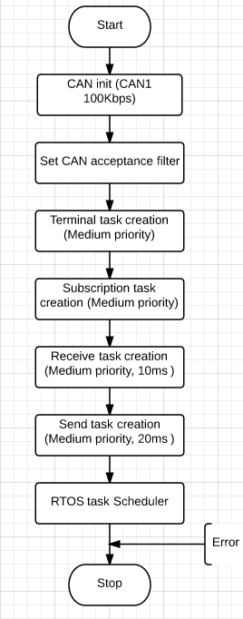
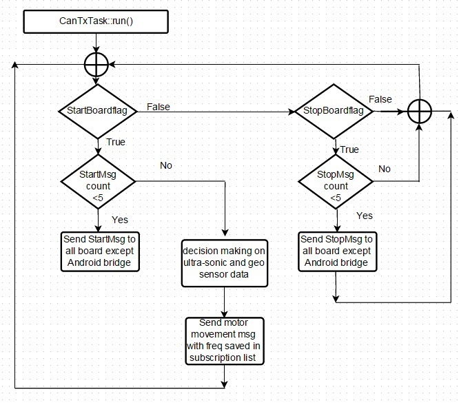
In our project controllers need data from other controllers at regular intervals of time. This requirement can be written in software through Subscription Publish Algorithm. The main idea of this algorithm is that Board A can get periodic messages from Board B by subscribing to Board B after startup only once and after that it keeps getting new data for the subscribed can message id at subscribed frequency. For out project subscription can be done at only 1,5,10,20,50Hz and if any other frequencies are tried it will mapped to of these frequencies depending of its nearest value i.e Board A can subscribe to Board B at any of above frequencies for given CAN A1_ID. Once Board A sends subscription message for can id A1_ID at say 5Hz board B adds a A1_ID entry and then starts sending can data of A1_ID at 5Hz. There is a separate TX task for these frequencies which sends new published data for all the entries of respective tasks.
Rx and Tx Tasks:
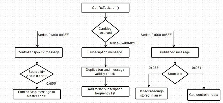
Master has one task to receive all the can messages and one task to send can messages. Page "http://www.socialledge.com/sjsu/index.php?title=Self-driving_Car" gives good explanation of canid and can message distribution.
Whenever Rx task receives 400 series messages i.e subscription messages it checks if entry for given can id has already been done its respective subscription list. If its new message then new entry will be done otherwise it is ignored. When 500 or 300 series messages are received then data of can message is saved.
Tx task is used to send can message from one board to another board. Also, subscription tx tasks are used to publish data at any of above mentioned frequencies.
Hardware Interface
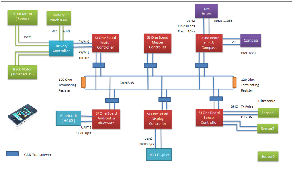
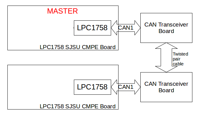
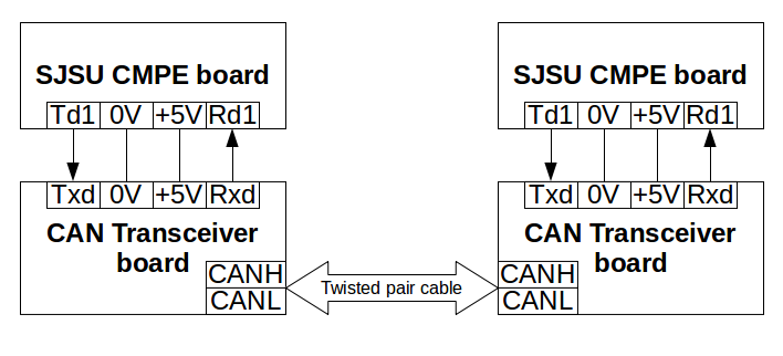
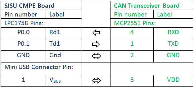
The following diagram explains the hardware communication:
The connections are made as follows:
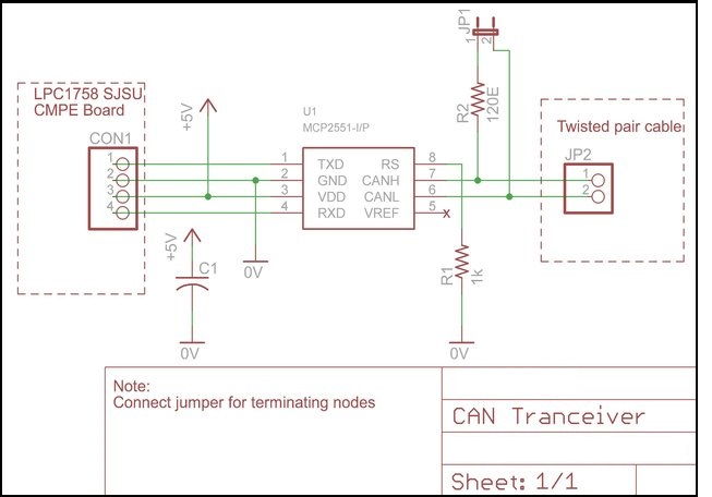
CAN Transceiver Schematic:
Software Design and Implementation
Android and Bridge
System Diagram
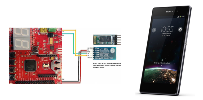
The above System Diagram shows the overall connection of the SJOne board and the HC05 bluetooth module. The module has 4 pins labeled on the back, VCC, GND, TXD and RXD. You might buy a module with two more pins KEY and STATE but it won't matter if you leave them open. The communication for configuration of the module is based on AT commands. There is one command for every thing, to set the device name, set the pin, set the baud rate and much more. All you have to do is to save these AT commands in the form of string and send each byte serially to the module using a simple for loop. Initially the baud rate is set to 9600. Following table shows few of the AT commands which you may require.
| Command | Response | Use |
|---|---|---|
| AT | OK | Used to verify communication |
| AT+NAMExyz | OKsetname | Sets the module name to “xyz” |
| AT+PIN1234 | OKsetPIN | Sets the module PIN to 1234 |
| AT+BAUD1 | OK1200 | Sets the baud rate to 1200 |
| AT+BAUD2 | OK2400 | Sets the baud rate to 2400 |
| AT+BAUD3 | OK4800 | Sets the baud rate to 4800 |
| AT+BAUD4 | OK9600 | Sets the baud rate to 9600 |
| AT+BAUD5 | OK19200 | Sets the baud rate to 19200 |
| AT+BAUD6 | OK38400 | Sets the baud rate to 38400 |
| AT+BAUD3 | OK4800 | Sets the baud rate to 4800 |
| AT+BAUD4 | OK9600 | Sets the baud rate to 9600 |
This bluetooth module requires 5V. Its Rx is connected to Tx of SJOne board and its Tx is connected to Rx of SJOne board with a common ground. We need bluetooth module in order to establish communication between the SJOne board and the Android Phone. In order to do this, code for bluetooth pairing, connecting and transmitting was thus written on Android SDK. There are three main tasks on the Android side :
- To send location coordinates (latitude and longitude) to GPS.
- To transmit "START" signal to the master.
- To transmit "STOP" signal to the master.
At the receiver, this data will be received by the Bluetooth Module and provided to SJOne(Android board) via UART. Then via CAN communication its passed on to the Master and GPS boards.
Software Developing Environment
The software developing Environment used for Android was Android SDK and for bridge we used Free RTOS. To develop an Android App for our self driving car, the first thing we needed was a proper connection between the Bluetooth module and our Android phone. For this we used the Bluetooth APIs available like Bluetooth Adapter, Bluetooth Device etc. Here the Bluetooth Adapter is used as the first step to setup the Bluetooth connection and to verify if the bluetooth is supported or not. The Bluetooth Adapter is returned when we call static BluetoothAdapter.getDefaultAdapter(). Secondly, it is very important that you enable the Bluetooth and this is done by calling startActivityForResult(). According to your requirement you can either use BluetoothAdapter.ACTION_REQUEST_ENABLE or BluetoothAdapter.ACTION_STATE_CHANGED. Third Task is the Discovery, for this we have to call startbtAdapter.startDiscovery(). Next Task is to scan the devices available for Pairing. This is done by BluetoothAdapter.ACTION_DISCOVERY_STARTED and BluetoothAdapter.ACTION_DISCOVERY_FINISHED. And if nothing is happening check if the Bluetooth is ON if not turnOnBT(). Next task is to pair the Devices. This is done by calling btAdapter.getBondedDevices(). This will return already paired devices with the Android Device you using. Next step is to connect the devices which are not already paired. These devices are paired by entering the password for the device. Next step is to initiate a Bluetooth Connection for sending the data. For this simply copy the code for "private class ConnectThread extends Thread" from the Bluetooth|Android Developer site. Final task is set the UUID to "00001101-0000-1000-8000-00805F9B34FB" and you are good to go. It is very important that you add Permissions in the Android Manifest.xml. The permissions that we used were:
   <uses-permission android:name="android.permission.INTERNET" />
   <uses-permission android:name="android.permission.ACCESS_NETWORK_STATE" />
   <uses-permission android:name="android.permission.WRITE_EXTERNAL_STORAGE" />
   <uses-permission android:name="com.google.android.providers.gsf.permission.READ_GSERVICES" />
   <uses-permission android:name="android.permission.BLUETOOTH_ADMIN"/>
   <uses-permission android:name="android.permission.BLUETOOTH"/>
Developing an Android App
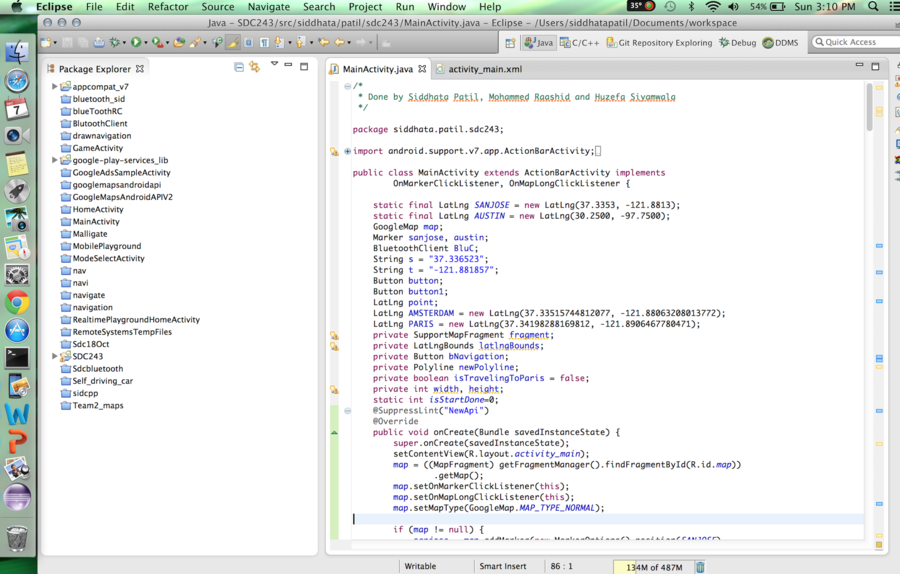
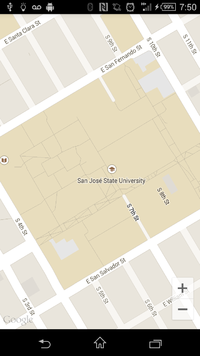
The very first stage was to create a Map fragment. For this we decided to go with the Google Map API V2. For this we need the "Google Play services" . To install this package go to Android SDK Manager, click on Google play services and click on install package. Once the package is installed, we have to import this library. After this we need to add the googleplay_services_lib to our project. To do this, goto Properties -> Android -> Click on the googleplay_services_lib -> Click on Add. In MainActivity.java import the following:
    import com.google.android.gms.maps.GoogleMap;
    import com.google.android.gms.maps.MapFragment;
Now add all the required permissions to your project
   <uses-permission android:name="android.permission.ACCESS_COARSE_LOCATION" />
   <uses-permission android:name="android.permission.ACCESS_FINE_LOCATION" />
   <permission
       android:name="siddhata.patil.sdc243.permission.MAPS_RECEIVE"
       android:protectionLevel="signature" />
Next step is the SHA1 fingerprint key. Goto Mac / Windows -> Preferences -> Android -> Build -> Copy the given SHA1 fingerprint key. Now go on the Internet and search for API Console - Google code. This is Google Developers Console. On left hand side you will see Services -> turn the tab ON for Google Maps Android API v2. Now again go on the left hand side and you will find API Access. Click on that. Generate new key -> Paste the copied SHA1 key ; "your package name" -> Click on Create. Your API key will be generated. Now copy this API key and paste this in your AndroidManifest.xml.
         <meta-data
           android:name="com.google.android.gms.version"
           android:value="@integer/google_play_services_version" />
         <meta-data
           android:name="com.google.android.maps.v2.API_KEY"
           android:value="Paste you API key" />
Now for the UI, under Activity_main.xml, we need to create a map fragment in Relative layout.
  <RelativeLayout xmlns:android="http://schemas.android.com/apk/res/android"
   xmlns:tools="http://schemas.android.com/tools"
   xmlns:map="http://schemas.android.com/apk/res-auto"
   android:id="@+id/LinearLayout1"
   android:layout_width="wrap_content"
   android:layout_height="wrap_content"
   android:orientation="vertical" >
   <fragment
         android:id="@+id/map"
         android:layout_width="match_parent"
         android:layout_height="match_parent"
         android:name="com.google.android.gms.maps.MapFragment"
         />
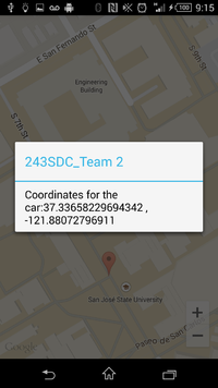
Now, for the second stage of our Android App, we had to create an On click function to select the Start and End coordinates for our car.
   public void onMapLongClick(LatLng point)
   {
    AlertDialog.Builder setPasswordDialog = new AlertDialog.Builder(this);
    setPasswordDialog.setTitle("243SDC_Team 2");
    setPasswordDialog.setMessage("Coordinates for the car:"+ String.valueOf(point.latitude) + " , "
    + String.valueOf(point.longitude));
    setPasswordDialog.show();
      if(isStartDone==0)
      {
      SANJOSE1 = new LatLng(point.latitude, point.longitude);
      Log.d("ADebugTag", "Setting Start Point");
      isStartDone=1;
      }
      else
      {
      Log.d("ADebugTag", "Setting End Point");
      SANJOSE2 = new LatLng(point.latitude, point.longitude);
      }
    }
Now for the third and the last stage of our Android Application, we had to add three buttons for the UI.
- Navigation Button - This button gives us a red color path between the selected Start and End coordinates.
- Start Button - Once the Start button is pressed, all the coordinates of the desired path are sent to the GPS board a character "a" is sent to the Master board indicating a start signal.
- Stop Button - Stop button sends character "z" to the Master board indicating a stop signal.
Sensor Controller
HC-SR04 Ultrasonic Sensor Features
- It is a four pin ultrasonic sensor. Four pins being; supply, ground, trigger and echo.
- The module is composed of; ultrasonic transmitter, ultrasonic receiver, and control circuit.
- It is a non-contact obstacle detector.
- Range of obstacle detection is from 2cm to 400cm.
- Requires, 5V 15mA supply.
- 15 degrees of measuring angle.
HC-SR04 Working Principle
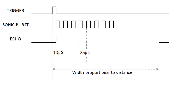
- When a short 10uS pulse is provided to the trigger input, the module will send out an 8 cycle burst of ultrasound at 40 kHz and make its echo pin a logic high.
- The Echo pin is lowered to logic low when the ultrasound burst is reflected off a distant object.
- Now, the width of this pulse on the echo pin is in direct proportion with the distance of the obstacle.
- Timing diagram for all these signals is shown in the above figure.
HC-SR04 Distance Calculation
- We know, speed of sound is 340m/s.
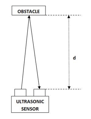
- In our sensor, ultrasonic sound waves needs to travel twice the distance of the obstacle as shown in the above diagram.
- From the pulse width, we know the time required to get an echo.
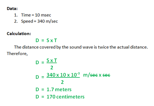
- For example, let us assume the time required to get an echo is 10msec, the following image shows how the distance is calculated.
Hardware Implementation
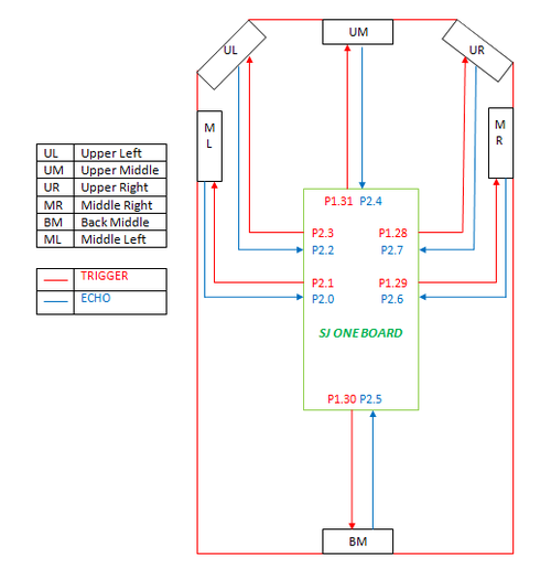
- As shown in the image below, we are connecting six such ultrasonic sensors.
- The front three and rear sensors are for obstacle detection, while the middle two sensors are for edge detection.
- All trigger and echo pins are directly connected to the hardware pins of SJ-One board.
Software Implementation
- We are using hardware timer 0 for calculating time between trigger and echo of all six sensors.
- All the sensors are triggered in sequential order to avoid interference from one another.
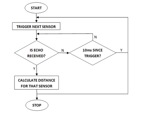
- The flowchart of our implementation is as shown in the figure below.
- As shown above each sensor will wait for the echo for 10msec. If it gets an echo within 10msec then it will calculate the distance proportional to that echo. If it doesn't get an echo within 10msec then it will assume the distance is greater than or equal to 170cms.
- Hardware timer is programmed to run continuously from the moment it is initialized.
- As shown below, we save the timer value in a variable when trigger is provided to a sensor.
   LPC_GPIO2->FIOPIN &= ~(1 << pin_number);
   LPC_GPIO2->FIOPIN |= (1 << pin_number);
   delay_us(10);
   LPC_GPIO2->FIOPIN &= ~(1 << pin_number);
   sensor0_trigger_time = lpc_timer_get_value(lpc_timer0);
- When echo is received, we subtract the saved timer value from the current timer value to calculate the time required for the ultrasonic wave to return. This distance calculation code is defined in ISR.
- As we have seen earlier, the echo pin makes a transition from high to low when echo is received. Hence, the ISR is called when there is a falling edge on the echo pin.
- The ISR code is as shown below.
   void sensor0_echo_function()
   {
       temp0 = lpc_timer_get_value(lpc_timer0) - sensor0_trigger_time;
       distance[0] = ((temp0) * 0.017) - 10;
   }
Algorithm
- . Trigger sensor 0.
- . If echo is not received within 10msec, register distance 0 = 170cm and skip next step.
- . If echo is received within 10msec, calculate distance 0.
- . Trigger sensor 1.
- . If echo is not received within 10msec, register distance 1 = 170cm and skip next step.
- . If echo is received within 10msec, calculate distance 1.
- . Trigger sensor 2
- . If echo is not received within 10msec, register distance 2 = 170cm and skip next step.
- . If echo is received within 10msec, calculate distance 2.
- . Trigger sensor 3.
- . If echo is not received within 10msec, register distance 3 = 170cm and skip next step.
- . If echo is received within 10msec, calculate distance 3.
- . Trigger sensor 4.
- . If echo is not received within 10msec, register distance 4 = 170cm and skip next step.
- . If echo is received within 10msec, calculate distance 4.
- . Trigger sensor 5.
- . If echo is not received within 10msec, register distance 5 = 170cm and skip next step.
- . If echo is received within 10msec, calculate distance 5.
- . Go to step 1.
I/O Unit
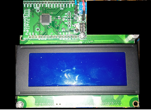
The I/O Unit consists of an LCD display to report the status of the car such as sensor values, heading and the current degree for the compass, latitude and longitude sent by Android. It also displays the CAN messages received per second. The LCD display that is being used in the car is SJONE Serial LCD display which runs on UART.
It is a 20x4 LCD display with a LCD driver which converts the UART characters to data and command signals for the LCD display.
The LCD has two modes of operation:
1. User Control mode
In this mode, the user controls the placing of LCD characters according to row and column by using GOTO command and $ character.
2. Smart LCD mode
In this mode, the user has to maintain a buffer for each line and print it on the line directly with scrolling enabled.
| LCD Pin | SJONE Pin |
|---|---|
| Rx | P0.10(TXD2) |
| Vcc | 5 V |
| GND | Ground |
LCD initialization
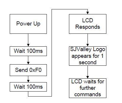
The LCD display has a driver programmed to detect the baud rate. When the board starts, the UART port is configured to get '0xF0' character.
Implementation
- LCD controller uses bypass mode of CAN and listens to all the messages. This is implemented to count the no. of messages per second on the CAN bus.
- A separate task is called which runs every 500 ms to display the messages.
- The controller receives the CAN messages in 8 bit and 16 bit unsigned integers and have to be converted to character to display on the LCD.
- We first store the CAN messages from sensor controller, geographical controller and android controller in global buffers.
- The value from the buffer is converted to character values and a string is constructed to print on the lines of LCD display.
- By default, the values from sensor, compass and android are displayed on the screen of LCD by refreshing it every 500 ms.
- For the purpose of debugging, the sensor values are displayed continuously when switch 1 is pressed, compass values are displayed when switch 2 is pressed, android values are displayed when switch 3 is pressed.
Geographical Controller
GPS Module Features
- Steps to change frequency to 10Hz using binary commands
- Parse NMEA message to get current longitude and latitude
- Distance calculation
HMC-6352 Digital Compass Features
- I2C 2-wire interface
- Full Integration of 2-Axis Magnetic Sensors and Electronics
- Low Voltage Operation (2.7 to 5.2V)
- 3-modes of operation
- Heading resolution 0.5 degree
Hardware Design
Add Block Diagram for both
Hardware Pin Diagram
Add pin diagram
Software Design
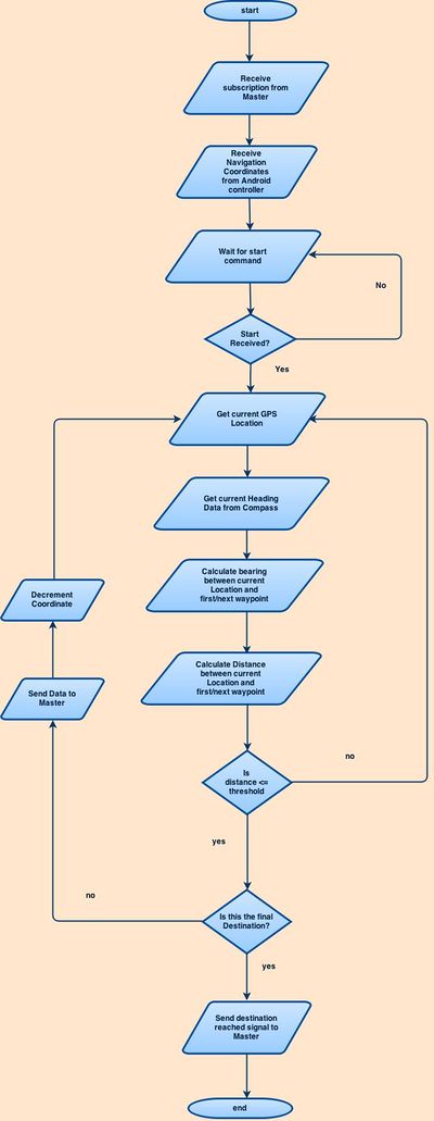
Received Android Data and related CAN subscription - CAN subscription Navigation, Destination Reached
- Navigate through received coordinates
- Destination reached command 4000 to master
Testing & Technical Challenges
| Sl. No | Test Case | Test Description | Result |
|---|
Android Testing
Command Log.d("ADebugTag", "Debugging!!!!") was used a lot of times. There was lot of debugging carried out since, one change in Android SDK would make us do change in the CAN communication in Free RTOS. The very first test carried out was the transmission of the data via bluetooth from Android phone to SJOne board. This was done by sending dummy coordinates to the SJOne board. Second test was carried out for the START and STOP buttons. This was tested by receiving the respective characters on the console. Third and final test was carried out for navigation. This test was done using actual App with the car thus involving GPS as well as Master.
Sensor Testing
HCSR04 Sensor Testing
LV-MaxSonar Sensor
Sensor Decision
- After testing the two sensors HCSR04 Sensor and LV-MaxSonar Sensor.
- Choosing HCSR04 sensor was better option due to the below advantages.
PROS:-
- The cost of HCSR04 is much more lesser than the LV-MaxSonar Sensor. (LV-MaxSonar == $30 and HCSR04 == $2 (cost effective) )
- Precision of both the sensor are same.
CONS:-
- There are two sensors one is used for transmission(Tx) and other one is reception(Rx), only one is used for transmission and reception as compared to LV-MaxSonar)
Hardware Timer
- All sensor were triggered using software timer.
- As software timer used to return values in milli seconds, the sensor values would be only in the multiple of 17.
- To get a wide range of the sensor value of distance, using hardware timer would support, as it used to return in micro seconds rather than in milli seconds as in software timer.
- Thus triggering the sensors using hardware timer and for calculation solved the issue of getting the wide range of values.
Sequentially Triggering of Sensors
- Triggering of multiple sensor together would cause sensor interfering with other sensors.
- This interfering with other sensors resulted in populating inaccurate readings, due to which the sensor was values were not reliable.
- Thus to solve the issue in sensor interfering with other sensor, triggering each sensor after the previous sensor value has been populated would resolve the issue.
- The cycle, i.e sequentially triggering of each sensor after calculating the previous value of sensor, for all the 6 sensors would be completed in 138 msec.
Limiting Max Distance
- For proper obstacle avoidance, we need to provide the sensor data to the master atleast 20 times per second, i.e. at 20Hz.
- Which means data from all six sensors must be calculated in 50msec.
- If we consider maximum distance (400cms) calculation for all sensors, we will require 23.5msec each sensor i.e. 141msec for all six sensors.
Abrupt Firing of Sensor
- As the sensor was providing on occasion an abrupt values. This mislead the decisions of the car proceedings.
- To overcome this issue, we have introduced a threshold value called DELTA. Which defines the acceptable range from the previous value.
- If the current value is in the range of the previous value +/- DELTA. Then this value is provided to the master and current value will be copied in the previous value.
- On the other way round, the current value is copied to previous value and wait for the next value from the sensor and check the above condition for range with previous value +/- DELTA.
- Thus to obtain a valid current value for a sensor, the maximun time would be around 20 msec. For all the sensor implemented on the car, the maximum delay would be 120 msec.
Challenges and Learning
Challenges in Android
There are two activities in Android. One is the bluetooth activity and other is the navigation activity. Switching from bluetooth activity to navigation activity would disconnect the bluetooth activity. This was one of the early challenges faced by us. We overcame this by changing the layout of our App. Then we combined the two activities in one activity itself by adjusting the dimensions. One more challenge faced by us was to differentiate latitude and longitude and give them separately to the GPS team. This was done by inserting one distinguishing character after each latitude and longitude so that the SJOne board could do the parsing and send it to the GPS board accordingly.
Future Enhancement
Conclusion
Project Video
Project Source Code
References
Acknowledgement
References Used
- Preetpal Kang, Lecture notes of CMPE 243, Computer Engineering, Charles W. Davidson College of Engineering, San Jose State University, Aug-Dec 2014.
- en.wikipedia.org/
