S12: Android Controlled Robot
Contents
Interfacing an Android Application with a Humanoid Robot
Abstract
For the CmpE 146 Project, an Android application will be created to interface with a humanoid robot. The user will be able to send instructions from the Android device to the robot wirelessly. The android application will first send commands to the wireless module, and then those commands will be translated into robot's movements using the LPC2148 microcontroller. The instructions will mainly be used to direct the movements of the robot. Overall, the goal of the project is to control the movements of the robot wirelessly by the Android device.
Objectives & Introduction
- Interface the RN-XV WiFly Module with the LPC2148 Microcontroller using UART1
- Create a TCP connection between the Android application and the wireless module, in which the wireless module will be the server and the android application will serve as the client.
- Obtain commands from the Android application and convert them into functions for the robot.
Team Members
- Daniel Garrett
- Saba Memon
- Nazmun Nahar
Roles & Responsibilities
| Member | Roles & Responsibilities |
|---|---|
| Daniel Garrett |
|
| Saba Memon |
|
| Nazmun Nahar |
|
Parts List & Cost
| Parts and Quantity | Cost |
|---|---|
| LPC2148 Microcontroller (1) | $100 |
| Motor Controllers (3) | $54 |
| RN-XV WiFly Module (1) | $35 |
| XBee Breakout Board (1) | $10 |
| Wowwee Robosapien Robot (1) | $230 |
| ASUS Transformer Tablet (1) | Supplied by CmpE department |
Design & Implementation
This section provides details for the overall design of the project and it's implementation.
Hardware Design
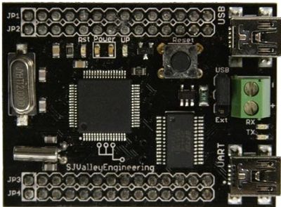
The main component of this project is the microcontroller because it controls the robot and obtains information from the android application via the wireless module. For this project, the LPC2148 microcontroller was used, which is illustrated in Figure 1.
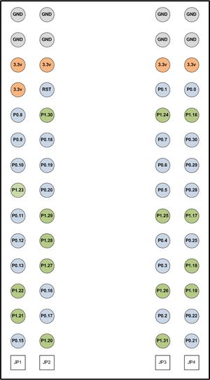
Specific pins on the microcontroller were used to connect the motors and the wireless module. A layout of the pin diagram of the microcontroller is illustrated in Figure 2, and Table 1 shows the pin assignments for the connections.
Table 1: The Pin Assignments for the Connections.
| LPC2148 Pin | Connection | Purpose |
|---|---|---|
| GND | Shared Ground | Shared Ground |
| 3.3V | Wireless Module P.1 | Power Module |
| P0.8 | Wireless Module P.3 (Rx) | UART1 Tx |
| P0.9 | Wireless Module P.2 (Tx) | UART1 Rx |
| P0.6 | Motor Controller Left Leg DIR | I/O, Direction control |
| P0.7 | Motor Controller Left Leg PWM | PWM2 |
| P0.22 | Motor Controller Right Leg DIR | I/O, Direction control |
| P0.21 | Motor Controller Right Leg PWM | PWM5 |
| P0.29 | Motor Controller Torso DIR | I/O, Direction control |
| P0.30 | Motor Controller Torso PWM | I/O, used as PWM |
The two main hardware components of the project were the motors and the wireless module. The hardware design for both of the components are are divided into their respective sections and provided below.
Motors
Seven different motors are provided for the robot, but only three of them are being utilized for this project: One for each of the legs and one for the torso, to tilt the upper body from side to side. For these three motor controllers, three PWM pins are needed. Table 2 shows the available PWM pins on the LPC2148 microcontroller.
Table 2. PWM Pins on the LPC2148 Microcontroller.
| PWM | Pin |
|---|---|
| PWM1 | P0.0 |
| PWM2 | P0.6 |
| PWM3 | P0.1 |
| PWM4 | P0.8 |
| PWM5 | P0.21 |
| PWM6 | P0.9 |
A problem lies when using three PWM pins. The problem lies in the fact that the P0.0 and P0.1 are also the Rx and Tx pins used for UART0, and P0.8 and P0.9 are also the Rx and Tx pins used in UART1. The UART0 is being kept active for testing purposes, to be able to output to the computer. UART1 is being used to communicate with the Wireless Module. The solution comes from the theory behind the PWM, or Pulse Width Modulation. The PWM signal is varied over the clock period based on its dutycycle. If it has a 100% dutycycle, it means that the PWM signal is high over the full clock period. If it has a 50% dutycycle, it is high over only half of that clock period. Essentially, a PWM signal with 100% dutycycle is a high signal while a PWM signal with 0% dutycycle is a low signal. This means that an I/O pin can send out a PWM signal if it contains only 100% dutycycle or 0% dutycycle. In order to move the robot's legs, the torso motor had to be incorporated in the project also. Since no other PWM pins were left, the torso motor was controlled by the I/O instead. The torso motor was also controlled by the I/O because it is one of the motors that requires less flexibility in PWM control.
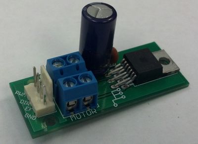
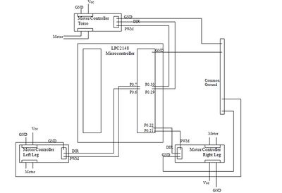
The motor controller being used for the motors is a simple one. It receives power and is regulated by the voltage converter placed on it, which converts it to 5V. It has a pins for common ground (GND), PWM, Direction (DIR), and Error Flag (EF). All of the pins were used except the Error Flag pin. Figure 3 illustrates the motor controllers being used for the project. Figure 4 displays a diagram of the connections made between the LPC2148 Microcontroller and the motors.
Wireless Module
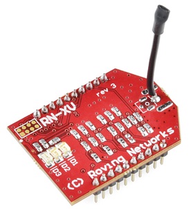
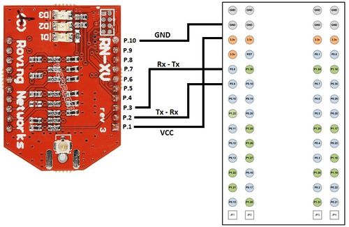
In order to make a wireless connection from the android application to the microcontroller on the robot, the RN-XV wireless module was used. This module is displayed in figure 5. The pin connections for wireless module are displayed in table 3 and a pin connection diagram displaying the connections between the wireless module and the microcontroller is displayed in figure 6.
Table 3. The Pin connections made between the LPC2148 Microcontroller and the RN-XV Wireless Module.
| LPC2148 Pin | RN-XV Wireless Module |
|---|---|
| VCC | P.1 (Vcc) |
| GND | P.10 (Gnd) |
| P0.8 (Tx) | P.3 (Rx) |
| P0.9 (Rx) | P.2 (Tx) |
Hardware Interface
For the project, it was necessary to implement some new drivers and create some interface between the LPC2148 Microcontroller, Motors, and Wireless Module. This section provides all of the interfaces between the various devices.
Motors
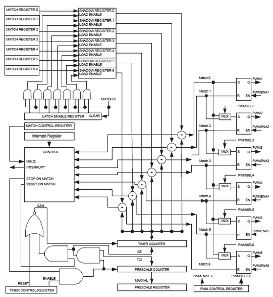
The main driver required for the hardware interface with the motors is the PWM driver. To better understand what is required for the driver, it is necessary to understand how the LPC2148 microcontroller handles PWM. Figure 7 illustrates the block diagram for PWM in the LPC2148 Microcontroller.
As this diagram illustrates, a Time Counter is implemented to keep track of the time intervals in between clocks. This basically partitions the clock frequency into a smaller frequencies determined by the pulse width provided by the driver. The timer increments at each interval and is compared to the specified dutycycle. When the time counter reaches the specified dutycycle, the output signal changes to high and remains high for the rest of the clock period. Everything then resets at the next rising edge of the clock, which creates the PWM signal.
The first task that needs to be completed in the PWM driver is setting the correct pins that are being occupied by the PWM. For the project, P0.7 and P0.21 are being used for PWM2 and PWM5, respectively. These pins are enabled to PWM. It is also necessary to make sure that the respective PWM registers are enabled as well, so that the PWM signal can output, as shown in the diagram. The time counter needs to be enabled and the appropriate pulse width desired needs to be stored. This is stored in Match 0. The matches in the block diagram represent the values that are being compared and Match 0 stores the value which forces the incrementation of the time counter. The other matches store the values being compared, represented by the respective dutycycles. For the driver, Match Register 2 and Match Register 5 need to be stored with the desired dutycycle. Since the dutycycle will change depending on the desired motor output, the dutycycle is set to 0 in the driver. Because the output pins are active low, 100 dutycycle is actually interpreted as minimum in this case. The last necessary addition to the PWM driver is enabling the latches. The latch enable register is what actually enables the match values to be output to be compared. Latch enable 2 and 5 are enabled in the latch register for this project.
Wireless Module
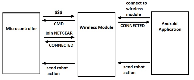
In order to communicate between the microcontroller and the wireless module, the UART1 driver was created. The UART1 driver was written similar to the UART0 driver, except the pin addresses and the vector address had to be changed. Once the driver was created, it was time to program the wireless module. In order to create a wireless connection and join a network, a few commands had to be transferred from the microcontroller to the wireless module. First of all, in order to enter into the command mode, an array with ‘$$$’ was sent out to the wireless module. The wireless module can respond back by presenting the either ‘$$$’ or ‘CMD’. If ‘$$$’ is received, then it illustrates that the module did not enter command mode, but if ‘CMD’ is received, then the module entered command mode. If the module does not enter command mode, then it exits out of the command mode and tries to go in command mode again until ‘CMD’ is received. After the wireless module enters command mode, then the ‘join NETGEAR’ command is sent, which allows the wireless module to join the NETGEAR network. Once this command is executed, then the user is able to connect the android application to the same network and send data wirelessly from the android application to the wireless module. Figure 8 illustrates the communication between the microcontroller, the android application, and the wireless module.
Software Design
For the software design of the project, creating an android application was one of the key components. One can follow the guidelines and instructions for installing the necessary software, such as java eclipse and the android SDK, on the Android Developer website provided in the References Section.
The Android Application was created from scratch and followed Android Development Cookbook guidelines. Android Operating System is Java based platform and Java language is used to implement the application. To start up with an Android Project, the following software needs to be installed:
- Eclipse (Java Edition)
- Android SDK
- Java SDK
- ADT Plugin for Eclipse
All the SDK need to be installed prior to start working on an Android Application. The essential software were downloaded from the Android Developer website.
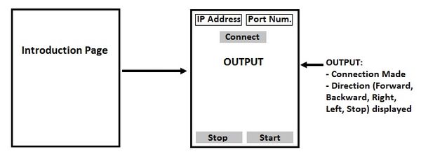
First of all, a layout for the application was created which was used to help create the application. Figure 9 illustrates the overall design of the application.
Once the layout for the android application was created, it was time to connect the android application to the wireless module. The user will first enter the IP Address and the Port Number of the wireless module and then press the ‘Connect’ button. If the IP Address and the Port Number are correct, then a Transmission Control Protocol (TCP) connection will be created. TCP protocol is used instead of UDP to ensure all of the data is sent properly. If the connection is created, then the output result will be displayed as ‘Connection Made’, else an error message ‘No connection’ will be displayed. Once the connection is made, the user will first press the ‘Start’ button to start the robot and send data from the android application to the wireless module.
The accelerometer is also incorporated in the project to obtain the direction (forward, backward, right, and left) when the user moves the android tablet in a certain direction. The accelerometer sensor is used to control the Robot’s movements using the tilting functionality of the Android Tablet. In order to use the tilting function, Sensor, SensorManager, SensorEventListener and SensorEvent classes are called in the program. The Accelerometer sensor data captures the changes of each coordinate and stores the value of X, Y and Z axis with the range of negative (-) 10 to positive (+) 10. The value of these axes changes according to the change of X, Y and Z axis. The Sensor, SensorManager, SensorEventListener and SensorEvent classes are the following:
Sensor: Sensor class holds all the sensors that the Android device has. All the sensors are named as sensor TYPE. For instance, Accelerometer sensor is listed as TYPE_ACCELEROMETER
TYPE_ACCELEROMETER: A sensor of Accelerometer type measures the acceleration applied to the Android Tablet. All the values of this sensor are measured as SI units (m/s^2). The Values is the array that contains the sensor value. Values[0]: Acceleration minus Gx on the x-axis Values[1]: Acceleration minus Gy on the y-axis Values[2]: Acceleration minus Gz on the z-axis
SensorManager: SensorManager is called in order to get access to the Android Tablet’s sensors. SensorManager gets an instance of the SensorManager class by calling a function called getSystemService() with the argument SENSOR_SERVICE. It allows the instance to access the desired sensor.
SensorEventListener: SensorEventListener used for receiving notifications from the SensorManager when sensor values have changed. It creates two function called onAccuracyChanged() and onSensorChanged().OnSensorChanged()function is called whenever the sensor value changes in the Android Application.
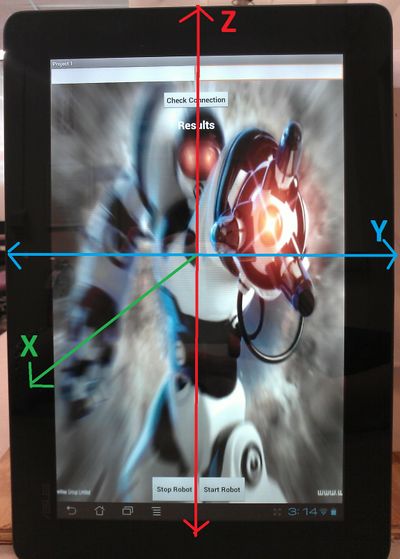
SensorEvent: The SensorEvent class represents a sensor event and holds information such as the sensor type, sensor data, and accuracy. The sensor data is structured by the coordinate –system and it is set as a default orientation. The X axis, Y axis and the Z axis do not swap when the tablet’s orientation changes. Figure 10 illustrates the coordinate-system defined in ASUS Transformer Prime Eee Pad.
The Y axis is horizontal and the positive value points to the right. The Z axis is vertical and the positive value points up. The X axis of this tablet points coming out of the screen of the tablet. The X, Y, and Z axis sensor values are obtained from the onSensorChanged() function and used to manipulate the tilting functionality of the Android Tablet, which are then converted into commands to control the movements of the robot. Table 4 displays the uses of the X, Y, and Z coordinate values which are used to determine the direction:
Table 4: The uses of the X, Y, and Z coordinate values to determine direction.
| X Coordinate | Y Coordinate | Z Coordinate | Direction Chosen |
|---|---|---|---|
| X<6 AND X>1 | Y<0 | Z>6 | Forward |
| X>6 | - | Z<6 | Backward |
| X<1 | Y>0 | Z<6 | Right |
| X<1 | Y<0 | Z>9 | Left |
Implementation
Since the robot is bipedal and not on wheels, making it move forward, backward, and turning right and left is not as easy as determining the direction of the motor. It is necessary to coordinate the legs and torso appropriately. As an example, consider the move forward function used in this project. The principle motion for the forward movement is the legs moving back and forth in opposite directions. This is not enough in itself to propel the robot forward; it is necessary to tilt the torso in the opposite direction of the leg that is about to move forward. It is necessary to time the tilt appropriately because doing it slightly before the legs move may cause an error in movement. Moving the torso with the legs shifts the robot's weight sufficiently on the backward moving leg to propel the robot forward. Alternating the tilts as well as alternating the leg movement with the appropriate timing is enough to move the robot forward, if maybe at a waddling pace. Similar techniques with timing the motors are used to move the robot backwards and to turn the robot to the left and to the right.
Implementing the wireless module and creating the android application was not as easy task. First of all, a network connection had to be created and most of the times, the connection would get disconnected and errors would appear on the screen. In order to make sure the connection is created at all times, the program is continuously checking for a proper connection, and if the connection is broken, then the program would try again to connect to the network. Once a successful connection is created, then the program would check for any incoming connection requests. Since the wireless module served as a server, it has to check if any clients are trying to connect to it. If a client does connect to the server, then information is sent from client to the server and the necessary functions are performed. A part of the program is illustrated below, which shows how the connection was checked at all times and created.
if(wiFiConnected()) //check to see if WiFi is connected and if it is not connected, exit out and connect again
{
if (incomingConnectionStatus()) // check for incoming connection requests, such as request from android application
{
for (;;)
{
//continuously compare strings that are incoming from android application and perform functions
}
}
}
The above program only illustrates how the connection was made from the server side. The connection from the client side (android application) had to be created also. In order to create a connection from the android application side, a try-catch method had to be used. First of all, the user enters the IP address and Port number for the wireless module in order to connect to it. After the user enters this information, the android application tries to connect to the wireless module. The Socket, which consists of the IP address and port number, is created in the try-catch method. The program tries to create the socket connection and if a successful connection is made, then 'Connection Made' is displayed on the screen, but if the socket is not created properly, then it goes in the catch and and 'No Connection' is displayed on the screen. If no connection was made, then the user can try again create a connection.
try
{
//create socket with IP address of Wireless module and port number
Socket s = new Socket(IP.getText().toString().trim(),Integer.parseInt(PN.getText().toString().trim()));
output.setText("Connection Made");
}
catch (UnknownHostException e)
{
output.setText("No Connection");
e.printStackTrace();
}
catch (IOException e)
{
e.printStackTrace();
output.setText("No Connection");
}
Once the connection from the android application and the wireless module were created, the data from the android application could easily be sent transferred to the wireless module and into the microcontroller to control the robot.
Testing & Technical Challenges
There were several challenges that arose while implementing this project. This section describes the testing techniques used as well as any challenges faced during the project.
Motors
There were a lot of difficulties at first in implementing the PWM driver. To make sure that the appropriate signals were being sent out an oscilloscope was used. Most pins just send a high or a low signal, but a PWM pin with any dutycycle other than 100% or 0% will show a rising edge. This way it is easy to see whether or not a PWM signal really is being sent. A DMM was also used to check voltage levels to ensure that the appropriate voltage was being applied in each instance. The microcontroller and the motor controllers each have a voltage adapter, so this isn't so be of a deal. While testing the movement functions Hercules was used to ensure that the right commands are being applied and that the timing is correct.
One issue that was faced was in power. The robot receives 4 D batteries and the many modules being used requires a lot of power. A fresh set of batteries allows everything to work fine, though. Also the motor in the right leg does provide some problems as it does not seem to move as freely as the other motors. This makes the robot turn as it attempts to walk forward. Adjusting the PWM signals solves this problem.
Wireless Module
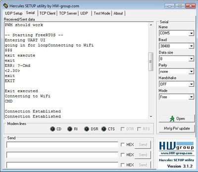
The wireless module is mainly used to create a wireless connection between the microcontroller and the android application. Various steps were taken to ensure the wireless module connects properly to the network. The wireless module was tested using the hercules program. In order to make sure the wireless module connects properly, the program was first divided into steps. Instead of automatically creating a connection, the user is first able to enter various commands, such as "join NETGEAR" and "show io" and observe the output. By allowing the user to enter these various commands, the user is easily able to connect to the network, but the problem rose when connecting automatically. When connecting automatically, sometimes the wireless module would not connect to the network. In order to ensure the wireless module automatically connects to the network, various loops were added in the program. For example, if the wireless module does not connect to the network, then it should automatically exit out by entering "exit" command and try to connect to the network again. This process is repeated until a successful network connection is made. Figure 11 illustrates the testing process in hercules. When the connection is not made, then an error is displayed, and the program tries to connect to the network again. A 'Connection Established' line is printed when the connection is properly established.
Android Application
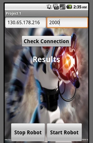
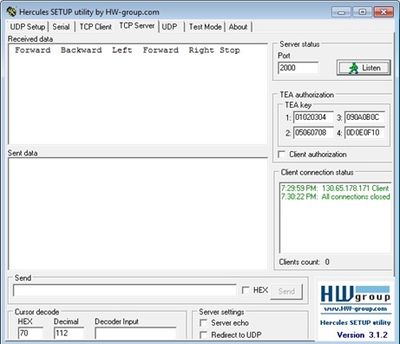
The purpose of the Android Application is to control the robot’s movement by sending the command wirelessly by using the tilting of the Android Tablet. Several steps were taken in order to test the Android Application. First, the application was tested on Hercules. The Android Application was loaded into the Android Tablet and tested on Hercules to ensure it receives the correct command. During the testing process, A TCP server was set up on Hercules to listen for any client. The Android Application was set up as a client and it communicated with the server by entering the IP address and the Port number of the server. Once the connection was established, the Android Application client sent command to the server side and server printed out the command it received from the client. Once the server successfully received the command from the Android Application, the Android application was disconnected from the Hercules server. Figure 12 displays the IP Address and the Port Number of the TCP server of the Hercules when the Android Client Application joins the server and figure 13 demonstrates the testing approach for the Android Application.
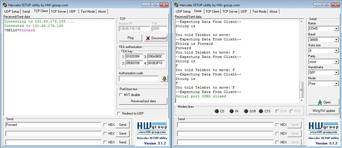
Next, the Wireless Module was tested with Hercules by setting up a TCP client on Hercules. Since Wireless Module is set up as a server, it is capable of receiving command from the client. The server side of the Wireless Module was tested when the client side joined the Wireless Module server by entering the IP address and the Port Number of the Wireless Module. After the connection was established, the TCP client sent command to the Wireless Module server and the server received the command. The following Figure 14 shows how TCP client connects to the Wireless Module Server using the IP address and the Port number of the module, and sends the command to the server. The Wireless Module server receives the command from the TCP client.
After the previous testing procedures were done and attained the satisfactory results, the Android Client Application and the Wireless Modules were tested together. This time, the IP address and the Port number of the Wireless Modules were entered to the Android Application to join the Wireless Module server. Once the connection was established, the Android Application sent the command to the Wireless Modules and the Wireless Modules received the command successfully. As a result, the Robot started to move according to the command the Wireless Module received.
The communication testing between the Android Application and the Wireless Module was done in steps to ensure that the client is sending the command and the server is receiving the command. The entire testing procedure was long but very helpful.
Conclusion
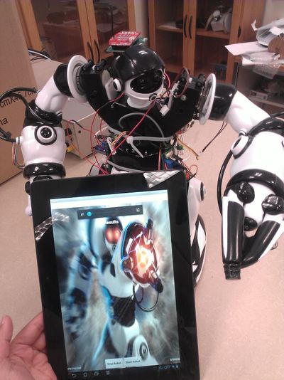
For the CmpE146 final project, the goal was to create a robot and control its movements using an android application. The goal was successfully accomplished as all of the tasks required were completed. The team also went above and beyond by using the accelerometer sensor to control the robots movements. Figure 15 illustrates the final project, illustrating the robot with the android application. While working on the project, the team came across many challenges such as communicating the android application with the wireless module and controlling the motors with the PWM signals. These challenges were resolved after much testing and debugging. Overall, the group gained much knowledge about working with the LPC2148 Microcontroller, the wireless module, and creating an Android Application. It was quite a challenging project, but after much hardwork and dedication from all of the team members, the project was successfully completed. For future, the team will control the arm movements from the android application and using a camera to obtain the robots vision on the android application.
References
Acknowledgements
- Preet Kang
- Allen Mamaril
- Bailey Wu
- Roger Luna
References Used
- Android Developer Website: http://developer.android.com/index.html
- LPC2148 Microcontroller Datasheet: Provided by Instructor
- RN-XV Wireless Module User Manual: http://dlnmh9ip6v2uc.cloudfront.net/datasheets/Wireless/WiFi/WiFly-RN-UM.pdf
Appendix
- TeleBot Group Website: http://telebotsjsu.doodlekit.com/home
- Project Video: http://www.youtube.com/watch?v=F3gaqJv2CEE&feature=youtu.be
- Zip File with Code: File:CMPE146 S12 T5 CODE.zip
