S14: Location Tracker
Contents
Grading Criteria
- How well is Software & Hardware Design described?
- How well can this report be used to reproduce this project?
- Code Quality
- Overall Report Quality:
- Software Block Diagrams
- Hardware Block Diagrams
- Schematic Quality
- Quality of technical challenges and solutions adopted.
Project Title
Abstract
The location tracker is designed to help you keep on eye on where someone—like your kid—is. An Android application communicates with the locator beacon to determine the location of the target and how to get there.
Objectives & Introduction
Two nodes shall be designed to communicate over GPRS/GSM network. Node Android requests data from node target. The Android application pinpoints the target and finds the fastest path to the target based on the received location. A SMS message is sent by the app to trigger the beacon to start sending its coordinates back. A GPRS/GSM module controlled by the SJ One Board on the beacon receives the SMS message, and triggers a new GPS coordinate reading from a GPS module. The GPS coordinates are sent back periodically through SMS messages for the app to map.
The project required the following objectives to be accomplished:
- Read GPS coordinates from GPS module
- Receive and send SMS messages from GPRS/GSM module
- Send and receive SMS messages from within Android app
- Map location of Android phone and target
- Retrieve and draw driving/walking path from source to target
Team Members & Responsibilities
- Arpit Amin
- GPS: communication and data parsing
- Caleb Chow
- Android application: SMS message handling, Google Map API and UI
- Cynthia Ho
- SMS: multitasking design to handle SIM900 and GPS modules
- Abraham Ruiz
- Android application: Source to destination path algorithms and Google Map API
Schedule
| Week# | Date | Task | Actual |
|---|---|---|---|
| 1 | 3/6 |
|
|
| 2 | 3/13 |
|
|
| 3 | 3/20 |
|
|
| 4 | 3/27 |
|
|
| 5 | 4/3 |
|
|
| 6 | 4/10 |
|
|
| 7 | 4/17 |
|
|
| 8 | 4/24 |
|
|
| 9 | 5/1 |
|
|
| 10 | 5/8 |
|
|
| 11 | 5/15 |
|
|
Parts List & Cost
| Part Name and Link | Price |
|---|---|
| SIM900 GPRS/GSM module | $48 |
| Ublox NEO-6M GPS Module | $23 |
| EasyAcc USB Power Bank DC 5V 2.1A, Output | $23 |
| Mini SIM card | $20 ($10 card + $10 T-Mobile prepaid service) |
| SJ One Board | $80 |
| Total | $194 |
Design & Implementation
Hardware Design
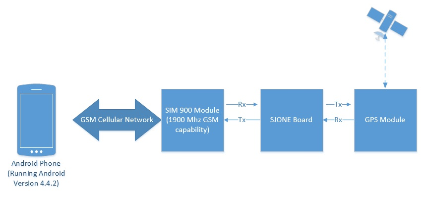
The Android app communicates with the SJ One board using the GSM network. Since the SJ One Board does not have an integrated GSM module, the SIM900 module was chosen to provide communication between the Android App and the SJ One Board. The SIM900 was interfaced to the SJ One Board via UART. A GPS module is required to connect with satellites to provide a triangulation area for the SJ One Board; Moreover, this GPS module must provide latitude and longitude data as fast as possible. It must also contain a footprint (including antenna). For this reason, we choose the Ublox NEO-6M GPS Module. This module weights 0.63 oz with the following dimensions: 1.22 in. x 0.91 in. x 0.16 in. (L X W X H). This GPS module was interfaced to the SJ One Board via UART. This module have four pin named power vcc, Ground gnd, transmitter tx and receiver rx. This module default baud rate is 9600 bps. This module can be programmed for different baud rate depending on requirement. Figure 1 shows the block diagram for this project and Figure 2 shows the locator beacon components.
Hardware Interface
The GPS module communicates using UART. The following table shows the hardware interface between the GPS module and SJ One board:
| SJ One Board | GPS Module |
|---|---|
|
VCC(3.3V) |
VCC (P1) |
|
Ground (GND) |
Ground (P4) |
|
UART2 RX (P2.9) |
UART TX (P3) |
The SIM900 GPRS/GMS module also communicates using UART. The following table shows the pin connections:
| SJ One Board | SIM900 GPRS/GSM Module | External 5V Power Bank |
|---|---|---|
|
VCC (P2) |
5V | |
|
Ground (GND) |
Ground (P1) |
Ground |
|
UART3 RX (P4.29) |
UART TX (P3) |
|
|
UART3 TX (P4.28) |
UART RX (P4) |
|
|
GPIO Output (P2.0) |
Power (P5) |
|
|
GPIO Output (P2.1) |
Reset (P6) |
Since the SIM900 and the GPS modules communicate via UART, There is only one device driver required for the SJ One Board: UART. UART 2 and UART3 drivers were reused from the provided base project.
Figure 3 shows a schematic containing the pin connections of the GPS and GPRS/GSM module.
Software Design
Locator Beacon
The locator beacon is composed of four parts: a SJ One board, GPS and GPRS/GSM modules, and 5V 2.1A battery pack. On the SJ One board, the processor communicates with GPS and GPRS modules. Both modules have their own task. The following explains the features of each task and introduces a few main functions.
- GPS Task - GPS task gets the data from the GPS module and parses the GPS data. The data is retrieved from the module in NMEA format. With the use of some computations, this NMEA format can be used to find coordinates that can be used by Google Maps. UART2 on the SJ One board is initialized at a baud rate of 9600 bps to communicate with the GPS module.
- init() - This task get the UART instance and initialize the UART bus at 9600 bps for GPS module to transmit the NMEA Data
- run()- As GPS output various lines of data, this task checks if the data is available or not. Then it locates the line that start with “$GPGLL”, as this line contains all the usefull data for this project. The second segment on this line is the latitude in NMEA format, and third segment is the direction N or S, indicating northern or southern hemisphere. In the same way, the fourth segment is longitude and fifth is E or W, indicating Eastern or Western. This task takes the NMEA format longitude and multiplies it with -1 if it indicates E, and multiplies latitude with -1 if it indicate S
- calculate()- This function take the value from the run task and converts the NMEA data to the coordinates value so that Google Maps can understand the coordinates and display the location on the maps
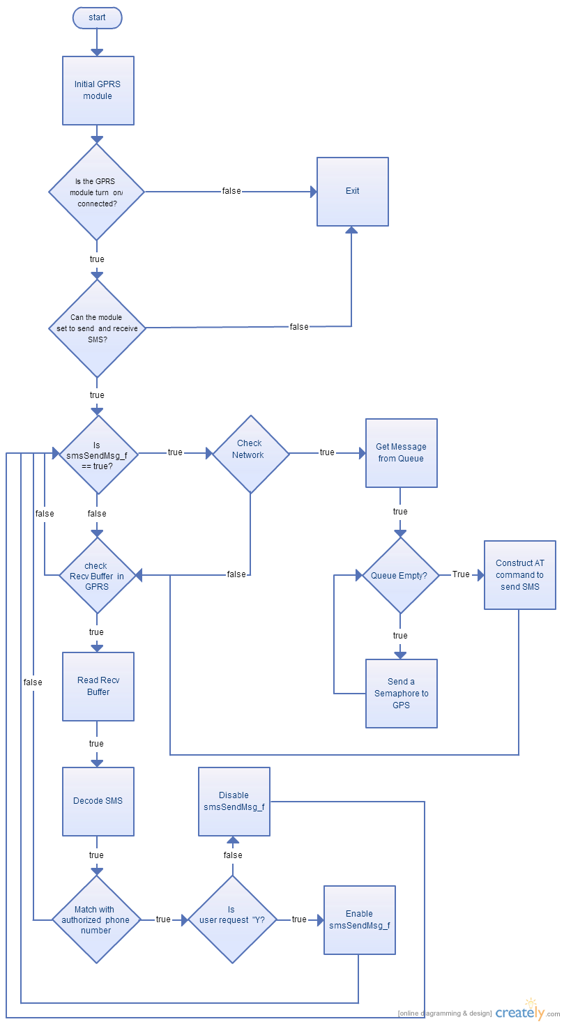
- GPRS/GSM Task - This task manages receiving and sending SMS messages. It sends a signal to the GPS task to obtain the current location, which is passed between the tasks using a queue. To communicate with GPRS module, UART 3 is used and its baud rate is set to 115200 bps. Then, the GPRS module is confirmed to be on by setting AT commands and getting a response. If GPRS module is not on, a reset signal and power signal are sent from SJSU One board.Then, SJSU One board turn off GPRS echo feature, and also setup the sending and receiving feature.
- init() - set baud rate, create binary semaphore and a queue to store message
- taskEntry() - Check if GPRS module is on, turn off the echo, set receive and send message format
- run() - This schedules SMS send and receive activities
- checkNetworkRegAndSendSMS() - This checks if the SIM card is registered with the Network. If it is, call pass the number and message to sendSMS(). If there is no message in the message queue, it sends a semaphore to GPS module to obtain a new coordinate
- sendSms(const char * number, char * message) - This gets the phone number and message and build a AT command and send it to GPRS module
- recvSms() - This checks the received buffer in GPRS if there is any message is arrived. If there is, go to readSMS()
- readSms(char * recvStr, int ) - This obtains the whole message from received buffer and uses smsDecoder() to get sender number and sender request. Then send it to userRequest
- userRequest(char *senderNum, char * msg) - This checks the phone number with the authorized phone number. If it is an authorized phone number, it starts sending SMS or stop sending SMS according to the request
Figure 4 shows the flowchart for the GPRS task.
Figure 5 shows the local variable that are used.
The local variable, gprs, is a pointer to uart to communicate with SIM900 module. The smsSendMsg_f is to indicate if the SMS should keep sending or not, and countDisplay is the number that is display on LED on SJ One board to indicate number of SMS is sent.
Android App
There are three main components/Java files in the Android application:
- MessagingReceiver
- This module is started when android app starts (from AndroidManifest)
- It knows when system receives an SMS message and passes the event to the MessagingService
- MessagingService
- This module retrieves the source and body of the SMS message from the event received
- The source phone number is validated based on the phone number set in the user settings
- Once validated, the body is validated and parsed to get the GPS coordinates
- The coordinates are passed to the MainActivity to be displayed
- MainActivity
- This module contains the UI for the app
- The device location is displayed when the app is started and continually updated
- Once a valid destination location is received, the location is displayed
- It chooses between walking path mode or driving path mode based on distance to the destination
- The fastest route to the destination is retrieved using the API from the gdaplibrary library
- A button is used to start and stop receiving GPS coordinates
- A settings page can be accessed to configure the target name and phone number
Please note that in order to use Google Maps API v2. you need to get the an Android certificate and the Google Maps API key. Directions on how to get this credential can be found here.
Figure 6 shows the software architecture diagram of the Location Tracker android app.
Implementation
This section includes implementation, but again, not the details, just the high level. For example, you can list the steps it takes to communicate over a sensor, or the steps needed to write a page of memory onto SPI Flash. You can include sub-sections for each of your component implementation.
Testing & Technical Challenges
Describe the challenges of your project. What advise would you give yourself or someone else if your project can be started from scratch again? Make a smooth transition to testing section and described what it took to test your project.
Include sub-sections that list out a problem and solution, such as:
My Issue #1
Discuss the issue and resolution.
Conclusion
Conclude your project here. You can recap your testing and problems. You should address the "so what" part here to indicate what you ultimately learnt from this project. How has this project increased your knowledge?
Project Video
Upload a video of your project and post the link here.
Project Source Code
Send me your zipped source code and I will upload this to SourceForge and link it for you.
References
Acknowledgement
Any acknowledgement that you may wish to provide can be included here.
References Used
List any references used in project.
Appendix
You can list the references you used.


