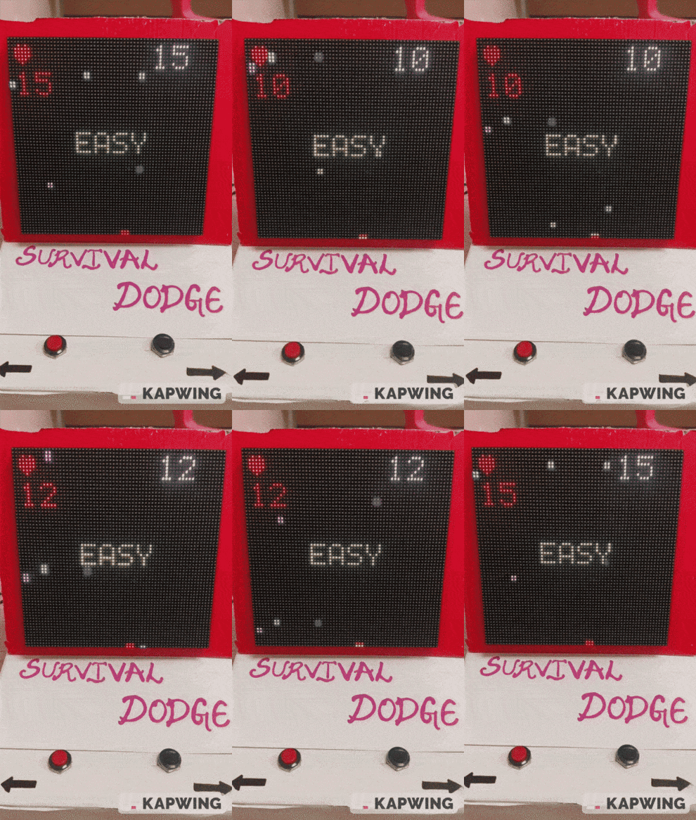
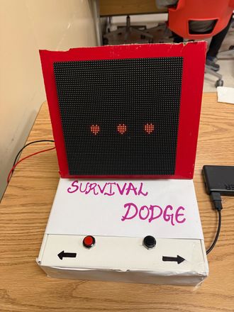
F24: Survival Dodge
Contents
Grading Criteria
- How well is Software & Hardware Design described?
- How well can this report be used to reproduce this project?
- Code Quality
- Overall Report Quality:
- Software Block Diagrams
- Hardware Block Diagrams
- Schematic Quality
- Quality of technical challenges and solutions adopted.
Project Title
SURVIVAL DODGE
Abstract
Survival Dodge is a classic arcade-style game focused on quick reflexes and survival, reminiscent of retro gaming experiences. This project aims to recreate the intense and fast-paced gameplay using the SJ-2 board and an LED matrix display. In this game, players control a character (or an object) that must dodge incoming obstacles from multiple directions, with the speed and frequency of obstacles increasing over time. The objective is to survive as long as possible, setting high scores based on survival time. Players will use buttons or a joystick to maneuver, with core implementation focusing on responsive controls, real-time collision detection, and adaptive difficulty for sustained challenge.
Objectives & Introduction
- "Survival Dodge" aims to create an engaging game where players maneuver a character to avoid obstacles and accumulate points, displayed on an LED matrix.
- As players progress, the game increases in difficulty by accelerating the obstacles, testing reflexes and enhancing engagement through simple button-based controls.
- Player controls a character using simple buttons (e.g., left, right). Obstacles spawn at random positions and move toward the player.
- Smooth display graphics during game play. Utilize the SD card as part of our design
- Further explore synchronization and task prioritization of tasks in an RTOS within a more complex application
Team Members & Responsibilities
Chandra Sekhar
- Develop Game Logic.
- Game State Machine handling.
- Develop Drivers for hardware.
- Integrating Hardware and Software
Uday Pesala
- Develop drivers for LED Matrix.
- Develop graphics drivers for displaying defined images to LED Matrix.
- Made the enclosure and body of the system.
- Game logic integration, testing and debugging.
Siva Prasad Reddy
- Developed Drivers for LED Matrix.
- Wiki Page Manager.
- Game logic integration, testing and debugging.
- Syncing game logic and add on features including New high Score Running parallely.
Schedule
| Week# | Start Date | End Date | Task | Status |
|---|---|---|---|---|
| 1 |
|
|
|
|
| 2 |
|
|
|
|
| 3 |
|
|
|
|
| 4 |
|
|
|
|
| 5 |
|
|
|
|
| 6 |
|
|
|
|
| 7 |
|
|
|
|
| 8 |
|
|
|
|
| 9 |
|
|
|
|
| 10 |
|
|
|
|
Parts List & Cost
| Item# | Description | Quantity | Price |
|---|---|---|---|
| 1 |
SJ2C Board |
1 |
$50.00 |
| 2 |
LED Display |
1 |
$70.49 |
| 3 |
Momentary switches |
5 |
$8.99 |
| 4 |
Jumper wires |
Pack |
$8.99 |
| 5 |
MP3 serial module |
1 |
$ 8.39 |
| 6 |
SD Card and Aux Cable |
1 |
$ 16.39 |
Design & Implementation
Hardware Interface
LED Matrix Display:
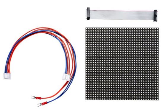
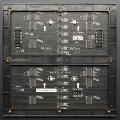
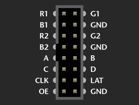
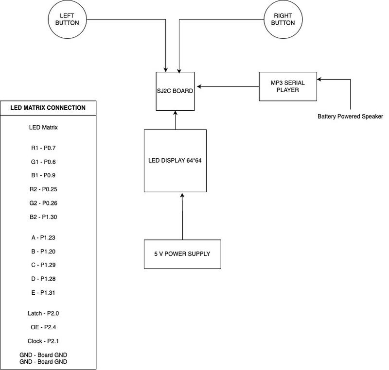
The 64 x 64 LED matrix comprises 4,096 pixels, each equipped with three channels for the colors red, green, and blue. The matrix uses a 5:32 decoder to address every two rows simultaneously, resulting in two distinct sections: the upper half includes rows 0 to 31, and the lower half consists of rows 32 to 64. To activate each LED, the corresponding RGB pins must be set to HIGH and fed into a 64-bit shift register that aligns with the matrix's 64 columns. The upper half of the display is managed by the RGB pins labeled R1, G1, and B1, while the lower half is controlled by R2, G2, and B2.
The figure and table below shows the pin-out of RGB LED matrix with description.
| Label | Name | Function |
|---|---|---|
| 1 | R1 | High R data |
| 2 | G1 | High G data |
| 3 | B1 | High B data |
| 4 | R2 | Low R data |
| 5 | G2 | Low G data |
| 6 | B2 | Low B data |
| 7 | A | A line selection |
| 8 | B | B line selection |
| 9 | C | C line selection |
| 10 | D | D line selection |
| 11 | CLK | CLOCK |
| 12 | LAT | LATCH |
| 13 | OE | Output Enable |
| 14 | GND | GND |
Momentary Press Buttons
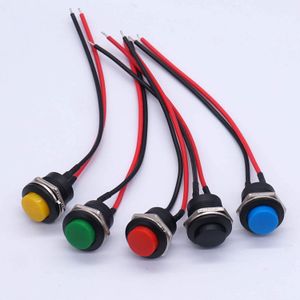
We utilized Weideer 16mm Push buttons sourced from Amazon for user input. These buttons offered a tactile response and a specific degree of switch travel, with each button featuring two terminals. We wired one terminal of each button to three distinct GPIO pins on the SJ2 Board for input signal reception. The other terminal was connected to the 3.3V Vcc of the SJ2. To avoid any floating inputs when the buttons were not active, we activated pull-down resistors in the software for these switches.
Hardware Design
Software Design
Implementation
Game Logic State Machine The game logic follows a state machine with multiple states. Below is a detailed flow of states.
START_SCREEN: Initially, the game is in the START_SCREEN state. Pressing any button during this state transitions the game to the GAME_START state.
GAME_START: This state activates the gameplay screen where the game officially begins. The player's score starts from zero. The player can move around to avoid obstacles. If the player touches an obstacle, the game moves to the UPDATE_LIVES state. If no button is pressed, it remains in this state until an obstacle is encountered or the timer runs out.
UPDATE_LIVES: In this state, the player’s lives are decremented due to a collision with an obstacle. If the player has remaining lives, the game returns to the GAME_START state to continue playing. If no lives remain, the game transitions to the GAME_OVER state.
GAME_OVER: This state is triggered when the player's lives are depleted or the game timer reaches zero. The gameplay stops, and the game over screen is displayed along with the final score. From here, pressing the start button restarts the game, sending it back to the START_SCREEN state.
Game Logic
Game States
- 1. Start Up
- 2. Game Running
- 3. Game Over
Player Task
Game state: start up
- 1. Display start up screen once per starting
- 2. Reset game parameters
Game state: game running
- 1. Display player and health bar on screen
- 2. Capture and move player location by switch signals
- 3. Check health and switch to game over state when player's health reaches zero
- 4. Check collision
Game state: game over
- 1. Display game over screen
Testing & Technical Challenges
Problem: The LED matrix display was experiencing flickering because the refresh rate was too low, causing visible delays in row/column updates. This resulted in an unstable display where LEDs appeared to blink or stutter instead of showing a smooth image.
Solution: We addressed the flickering issue in the display by optimizing the duty cycle through several key strategies. First, we increased the refresh rate to ensure that the rows and columns of the display are updated at a high frequency, specifically above 60 Hz. This rapid updating helps to stabilize the image. Next, we balanced the ON/OFF time of each row and column to maintain consistent brightness across the display. Finally, we implemented precise timing control by fine-tuning the delays and synchronization within the microcontroller code. This adjustment helps avoid any overlap or skipped updates, thereby reducing flicker and enhancing the visual smoothness of the display.
Conclusion
Developing "Survival Dodge" was a highly engaging and stimulating experience that kept us constantly intrigued. Tackling the various technical challenges, particularly in adjusting the game dynamics and LED matrix display, enhanced our practical problem-solving skills. Through this project, we applied key concepts from our game design and software engineering coursework, gaining deeper insights into real-time system management and user interface design. Collaborating on this project not only honed our teamwork and time management skills but also boosted our confidence in handling complex embedded systems and preparing for technical interviews.
Project Video
Upload a video of your project and post the link here.
Project Source Code
https://gitlab.com/chandrasekhar2499/sjtwo-c/-/tree/test?ref_type=heads
References
Acknowledgement
We would like to sincerely thank Professor Preetpal Kang for his all-round guidance, feedback, and support. His classroom lectures were significant in imparting knowledge on Advanced Computer Design.
References Used
Appendix
You can list the references you used.
