S14: Smart Weather Clock
Contents
Grading Criteria
- How well is Software & Hardware Design described?
- How well can this report be used to reproduce this project?
- Code Quality
- Overall Report Quality:
- Software Block Diagrams
- Hardware Block Diagrams
- Schematic Quality
- Quality of technical challenges and solutions adopted.
Project Title
Abstract
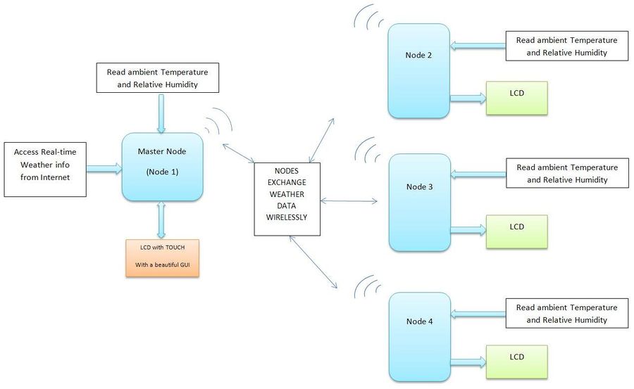
We plan to make four nodes of Weather Clocks that can communicate with each other as well as access the real-time weather from the Internet. The clocks also measure the indoor Temperature and the Humidity. All this information is displayed on a user-interactive graphic LCD with touchscreen. Each node can access the information of every other node as requested by the user. And of course, they also display the time.
Objectives & Introduction
- The main objective is developing a custom wireless protocol using the Nordic Wireless Mesh Network that can be used for communication of the four nodes.
- We also plan to access the real time weather information from the internet. The user can input the location of the city, and our clock will fetch the data from the internet and display it. To implement this, we have decided to use the "Electric IMP". We are giving our clocks the IoT (Internet Of Things) functionality so we can access our clocks virtually from anywhere.
- To make the clocks interactive, we would be using a Graphic LCD with touchscreen(uLCD-32PTU from 4D systems) and design a beautiful GUI. The user can select what information he wishes to see by clicking the icons. The user can also access the information from the other three nodes. The LCD would be interfaced on UART.
- To measure the indoor temperature and humidity, we would be using the DHT-22 sensor which can measure both. It's a One-wire sensor which sends out the data in pulses when requested. Measuring the length or time period of these pulses tells us if the data is logic '1' or '0'.
- All weather information will be logged in the Flash memory and will also be displayed on the graphic LCD as a graph of the parameter v/s time when requested by the user.
Team Members & Responsibilities
- Dhaval Parikh
- (Hardware design, sensor and Graphic Touch Screen LCD interface)
- Akshar Ranka
- (Electric Imp and 16x2 LCD interface)
- Huzefa Siyamwala
- (Wireless Communication (Server) and software integration)
- Raashid Kheruwala
- (Wireless Communication (Client) and LCD Interface)
Schedule
| Sr. No | Start Date | Projected End Date | Actual End Date | Task | Status |
|---|---|---|---|---|---|
| 1 | 3/1 | 3/7 | 3/7 | Finalise Component listing and Order Placement | Order Placed |
| 2 | 3/8 | 3/15 | 3/18 | Study of nordic wireless, Graphics LCD, electric Imp | Components Received. Testing begins! |
| 3 | 3/16 | 3/21 | 4/17 | Unit Testing for Graphics LCD, Algorithm and interface of Temp and RH Sensor | Made basic GUI on graphic LCD. Can send and receive data from LCD. Facing problems with Sensor! Working on it. |
| 4 | 3/22 | 3/28 | 4/3 | Getting Data from internet using Electric Imp | Data successfully received from Electric Imp using Openweather.org API's. Real-time weather info now available! |
| 5 | 3/29 | 4/4 | 4/17 | Integrating peripherals with SJ-One, Establishing communication between 4 nodes | Delay in integrating peripherals as sensor not working as desired. Will be done soon. Protocol defined and wireless communication established successfully between 2 nodes. |
| 6 | 4/9 | 4/15 | First phase of Testing / Happy path Testing | Integrated graphic LCD with the Electric Imp. Now displaying real-timer weather on the graphic LCD. Now working on the GUI. Problem with sensor found. Running behind by a week. | |
| 7 | 4/16 | 4/ 21 | Bugs Resolving | Issue with sensor resolved. Observed the data pattern on oscilloscope. Now working on reading data. Also working on communication between 4 nodes. | |
| 8 | 4/22 | 4/30 | Integrating the modules. | Sensor working perfectly. Electric Imp can access weather info from different cities. Now working on Hardware design, integration of all modules and bugs resolving. Back on track! | |
| 9 | 5/1 | 5/6 | Final Testing | Open | |
| 10 | 5/7 | 5/15 | Open |
Parts List & Cost
| Qty | Description | Manufacturer | Part Number | Total Cost |
|---|---|---|---|---|
| 1 | Serial TFT LCD - 3.2" w/ Touch | 4D Systems | uLCD-32PTU-GFX | $84.00 |
| 1 | Electric Imp Breakout board | Electric Imp | BOB-11400 | $20.00 |
| 4 | Humidity and Temperature Sensor- RHT03 | Sparkfun | SEN-10167 | $44.00 |
| 1 | SJOne Board | SJSU | - | $80.00 |
| 1 | Electric Imp card | Electric Imp | - | $30.00 |
| Total Cost | increasing! |
Design & Implementation
The design section can go over your hardware and software design. Organize this section using sub-sections that go over your design and implementation.
Hardware Design
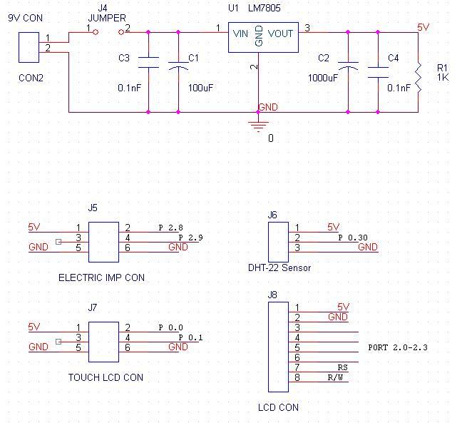
Discuss your hardware design here. Show detailed schematics, and the interface here.
Hardware Interface
In this section, you can describe how your hardware communicates, such as which Buses used. You can discuss your driver implementation here, such that the Software Design section is isolated to talk about high level workings rather than inner working of your project.
Our hardware module consists of following components:
1. Electric Imp
- Its a device that we are using in our project to connect to the internet. Electric imp is equipped with inbuilt SPI, I2C and UART ports. We are using UART port to communicate with the SJ-one board in this project. There are three UART configuration in the hardware that can be used in software, UART12, UART57 and UART1289. UART12 and UART57 are used for regular Rx and Tx communication. Pins 1 and 5 are used for transmission whereas pins 2 and 7 in the respective configurations are used for reception. UART1289 configuration is used for transmission and reception with flow control signals RTS and CTS.
- We have used UART57 mode for our project. Thus to interface and achieve communication between electric imp and SJ-one board, we have to connect Tx of imp with Rx of SJ-one and Tx of imp with Rx of SJ-one. By interfacing in this fashion, we make sure that data that is transferred by either imp or SJ-one will be received at the receiving end.
2. Graphics Touch Screen LCD
3. Temperature and Humidity Sensor(DHT-22)
Software Design
Server:
The main task of server is to provide communication link with all client nodes and periodically update itself with data from client node. It also need to refresh itself with real time data available from internet (openWeather API's) using electric imp.
Pseudo Code:
Server Code
    int32_t main(){
            /// initialize all input/output devices
            gLCD_Imp_init()
            while(1){
                  recieveDataFromClient();
                  updateDatatoLCD();
                  delay();
            }
     }
Initialize Graphics LCD(UART3) / Electric Imp(UART2) ports
     int32_t gLCD_Imp_init(){
               /// Power up
               LPC_SC->PCONP |= power_on_uartx;
               /// For enabling clock to UARTx
               LPC_SC->PCLKSEL1 &= ~(3 << 16);
               LPC_SC->PCLKSEL1 |= (1 << 16);
               /// Selecting UARTx TX/RX pin from Multiplexed port pins
               LPC_PINCON->PINSEL4 &= ~(0xF << 16);
               LPC_PINCON->PINSEL4 |= (0xA << 16);
               /// Enable DLAB for setting Baud Rate
               LPC_UARTx->LCR = enb_DLAB;
               LPC_UARTx->DLM = 1; //1;
               LPC_UARTx->DLL = (clock) / (16 * 9600);
               LPC_UARTx->LCR = 3;
               /// Enable fifo mode
               LPC_UARTx->FCR = ((1 << 0) | (1 << 6));
               /// Enable RDA interrupt
               LPC_UARTx->IER = 1;
               /// Hooking up Interrupt Handler
               NVIC_EnableIRQ(UARTx_IRQn);
     }
Receive data from Client Nodes
      int32_t receiveDataFromNodes(){
                Loop until response from all Nodes are received
                For node i,
                       wireless_send_packet(Client_Address,mesh_pkt_ack_app,FLAGS);
                       wait for response, until predefined time
                       if(wireless_get_ack_packet()){
                               wireless_deform_packet(buffer);
                               update sensor array data
                       }
                       iterate through other node
      }
Recieve live realtime data from internet
       typedef struct electric_imp_buffer{
             char city[16];
             char description[20];
             char temperature[10];
             char humidity[5];
             char datetime[20];
       }electric_imp_buffer;
       electric_imp_buffer buffer;

        int32_t UART3_IRQHandler(){
            /// We have configured Electric imp to send size of data
            /// as first two bytes of payload
            /// And each field of payload is separated by '#'
            char ch;
            if(counter<2){
               electic_imp_buffer=electric_imp_buffer<<8;
               electric_imp_buffer|= LPC_UART3->RBR;
            }else{
               while((ch=LPC_UART3->RBR)!='#'){
                   buffer.city[counter++]=LPC_UART3->RBR;
               }
               counter=0;
               while((ch=LPC_UART3->RBR)!='#'){
                   buffer.description[counter++]=LPC_UART3->RBR;
               }
               counter=0;
               while((ch=LPC_UART3->RBR)!='#'){
                   buffer.temperature[counter++]=LPC_UART3->RBR;
               }
               counter=0;
               while((ch=LPC_UART3->RBR)!='#'){
                   buffer.humidity[counter++]=LPC_UART3->RBR;
               }
               counter=0;
               while((ch=LPC_UART3->RBR)!='#'){
                   buffer.datetime[counter++]=LPC_UART3->RBR;
               }
            }
      }
Update data to LCD
      int32_t updateGLCD(){
               /// Writing commands to graphics LCD in specified format
               write_obj_to_display(WRITE_OBJ, GENIE_OBJ_METER, 0, 0,
                       (a[NO_OF_NODES - 1][1] / 10));
               write_obj_to_display(WRITE_OBJ, GENIE_OBJ_THERMOMETER, 0, 0,
                       (a[NO_OF_NODES - 1][0] / 10));
               write_obj_to_display(WRITE_OBJ, GENIE_OBJ_LED_DIGITS, 1, 0,
                       (a[NO_OF_NODES - 1][0] / 10));
               write_obj_to_display(WRITE_OBJ, GENIE_OBJ_LED_DIGITS, 2, 0,
                       (a[NO_OF_NODES - 1][1] / 10));
      }
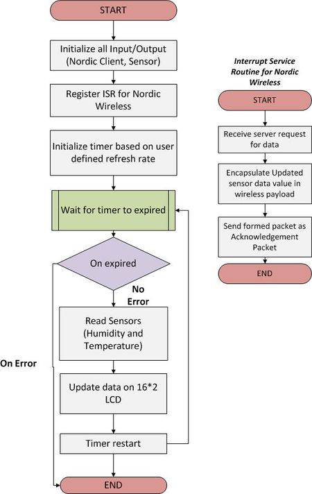
Client Node:
Pseudo Code:
Client Code
    int32_t main(){
            /// initialize all input/output devices
            Sensor_LCD_init();
            while(1){
                 writeDatatoLCD();
                 delay();
            }
     }
Setting Node Address
    int32_t setNodeAddress(uint32_t address){
           return (int32_t) mesh_set_node_address(address);
    }
ISR For Nordic Wireless receiving Server Request
    void NORDIC_UartHandler(){
        if (wireless_get_rx_pkt(&pkt, 100)) {
           /// Check if we were asked for an application ACK
           if (wireless_is_ack_required(&pkt)) {
                uint8_t tempOpcode=0;
                uint8_t humidityOpcode=1;
                wireless_form_pkt(&pkt, pkt.nwk.src, mesh_pkt_ack_rsp, 1,
                                      4,&tempOpcode,sizeof(tempOpcode),
                                      &temp_data,sizeof(temp_data),
                                      &humidityOpcode,sizeof(humidityOpcode),
                                      &rh_data,sizeof(rh_data);                                       );
            }
        }
         wireless_send_formed_pkt(&pkt);
    }
Implementation
1. Electric Imp
1.1 Electric Imp Bringup:
It’s an easy to use device using which we can connect our LPC micro-controller to the internet. By connect I mean we can fetch the data from web pages in real time. This data can then be used for processing such as controlling the sensors, motors, LED’s etc. So, using this data we can build and control systems without being present in the same area or any part of the world. Think of an air-conditioner, music player or entire home automation system which can be monitored and controlled from any part of the world via mobile phone or web browser. It has grown on the power of Internet of Things which has picked momentum in the recent time and combined the networking and embedded worlds.
Testing & Technical Challenges
Describe the challenges of your project. What advise would you give yourself or someone else if your project can be started from scratch again? Make a smooth transition to testing section and described what it took to test your project.
Include sub-sections that list out a problem and solution, such as:
My Issue #1
Discuss the issue and resolution.
Conclusion
Conclude your project here. You can recap your testing and problems. You should address the "so what" part here to indicate what you ultimately learnt from this project. How has this project increased your knowledge?
Project Video
Upload a video of your project and post the link here.
Project Source Code
Send me your zipped source code and I will upload this to SourceForge and link it for you.
References
Acknowledgement
Any acknowledgement that you may wish to provide can be included here.
References Used
List any references used in project.
Appendix
You can list the references you used.


