F19: Tower Defense in Space
Contents
ABSTRACT
My abstract goes here.
INTRODUCTION AND OBJECTIVES
|
RC CAR OBJECTIVES | ||||
|---|---|---|---|---|
|
| ||||
|
TEAM OBJECTIVES | ||||
|---|---|---|---|---|
|
| ||||
|
CORE MODULES OF TOWER DEFENSE | ||||
|---|---|---|---|---|
| ||||
|
PROJECT MANAGEMENT ADMINISTRATION ROLES | ||||
|---|---|---|---|---|
| ||||
|
TEAM MEMBERS & RESPONSIBILITIES | ||||
|---|---|---|---|---|
|
Team Members |
Administrative Roles |
Technical Roles | ||
|
|
| ||
|
| |||
|
|
| ||
|
| |||
SCHEDULE
|
TEAM MEETING DATES & DELIVERABLES | ||||
|---|---|---|---|---|
|
Week# |
Date Assigned |
Deliverables |
Status | |
| 1 | 10/15/19 |
|
| |
| 2 | 10/22/19 |
|
| |
| 3 | 10/29/19 |
|
| |
| 4 | 11/5/19 |
|
| |
| 5 | 11/12/19 |
|
| |
| 6 | 11/19/19 |
|
| |
| 7 | 11/26/19 |
|
| |
| 8 | 12/3/19 |
|
| |
| 9 | 12/10/19 |
|
| |
BILL OF MATERIALS (GENERAL PARTS)
|
MICRO-CONTROLLERS | ||||
|---|---|---|---|---|
|
PART NAME |
PART MODEL & SOURCE |
QUANTITY |
COST PER UNIT (USD) | |
|
|
| ||
HARDWARE INTEGRATION PCB
Hardware Design
The hardware integration PCB was designed with two goals:
1. Minimize the footprint of the onboard electronics
2. Minimize the chances of wires disconnecting, during drives
To accomplish these goals,
The board consisted of n layers:
layer name
Technical Challenges
Design
- Balancing priorities between HW design and getting a working prototype
Assembly
- Wireless antenna connector on master board not accounted for in footprint, it may have to be removed to avoid interference with one connector.
Bill Of Materials
|
HARDWARE INTEGRATION PCB | ||||
|---|---|---|---|---|
|
PART NAME |
PART MODEL |
QUANTITY |
COST PER UNIT (USD) | |
TEST
In order
Hardware Design
During
We used
MOTOR CONTROLLER
Hardware Design
The motor board
1 pin
1 pin f
1 pin
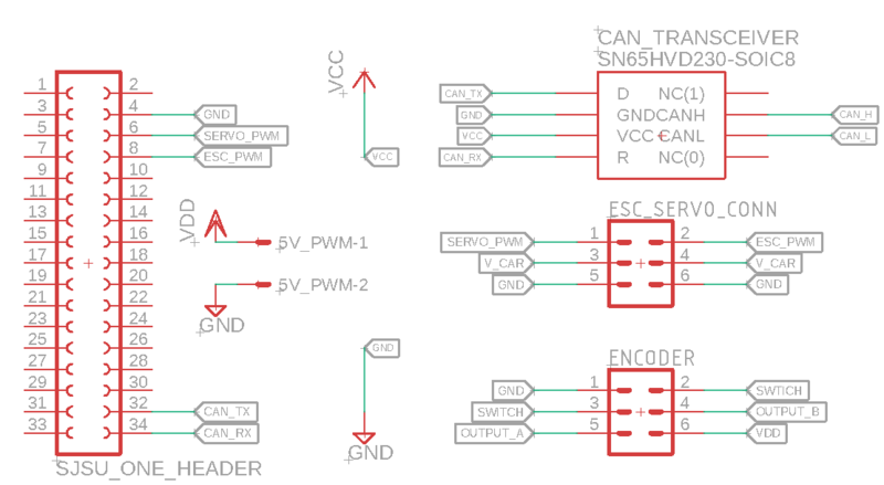
The ESC was included with the RC we purchased and it was interfaced with 3 pins:
1 pin fo
Manag
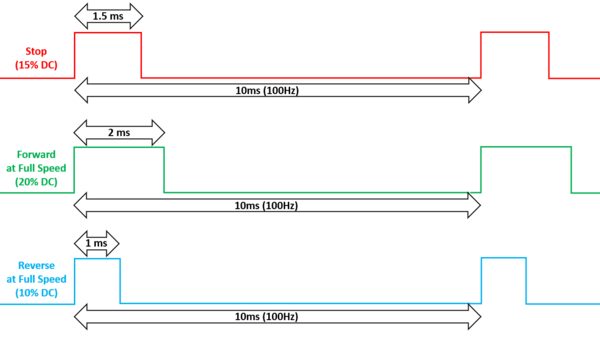
Managing wheel spin was a more complicated process. The ESC also requires a PWM signal in order to operate, but is not as simple as the servo's operation.
In or
S
Speed Control Timing Diagrams
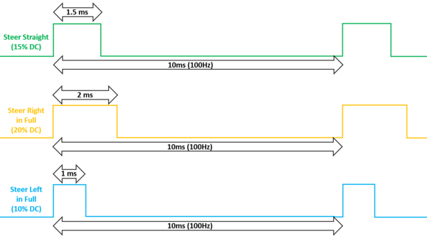
Steering Control Timing Diagrams
Motor Controller Schematic
Software Design
Periodic Callback: Init (beginning of program)
Periodic Callback: 1Hz (every 1sec)
- Che
Periodic Callback: 10Hz (every 100ms)
- Sen
Technical Challenges
SJOne PWM
W
Encoder
The
Bill Of Materials
|
MOTOR CONTROLLER | ||||
|---|---|---|---|---|
|
PART NAME |
PART MODEL |
QUANTITY |
COST PER UNIT (USD) | |
|
|
| ||
SENSOR CONTROLLER
Hardware Design
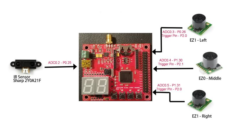
Sen
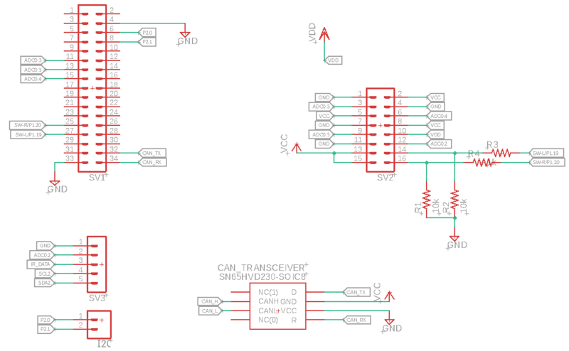
Sensor Controller Schematic
CAD Design
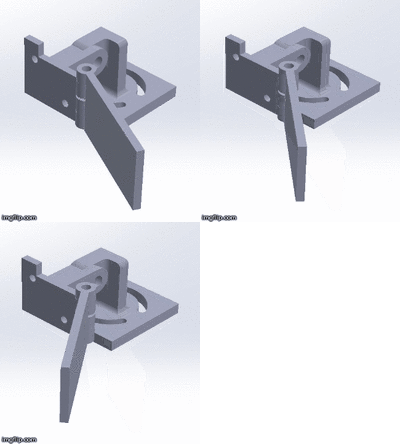
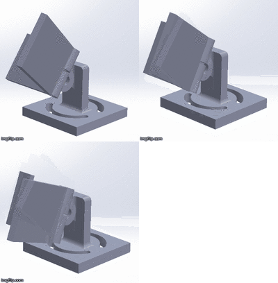
We g
Placement for the Ultrasonic Sensors
We r
Sensor Value Conversion
In or
Software Design
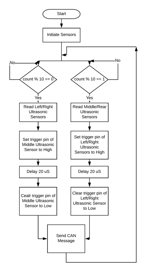
Flowchart
The f
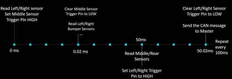
Timing Diagram
Technical Challenges
Sensor Interference
We saw :
- Higher
- Instead of l
Power Deficiency
At first
Unstable HR-04 Readings
At fi
ADC Supply Voltage
The mid
Slow car response to obstacle due to large queue size (running average)
During
Bill Of Materials
|
SENSOR CONTROLLER | ||||
|---|---|---|---|---|
|
PART NAME |
PART MODEL |
QUANTITY |
COST PER UNIT (USD) | |
|
|
| ||
|
|
| ||
|
|
| ||
CONCLUSION
This pr
Project Video
Project Source Code
Advice for Future Students
- FORM YOUR TEAM AS EARLY AS POSSIBLE AND START WORKING ON THE PROJECT AS EARLY AS POSSIBLE (WEEK 1 IF POSSIBLE)
- If you are
