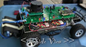
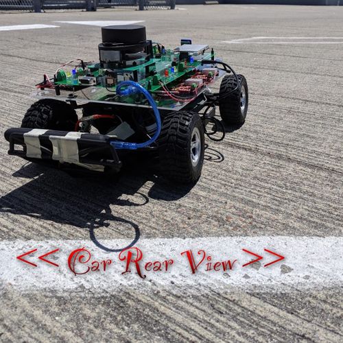
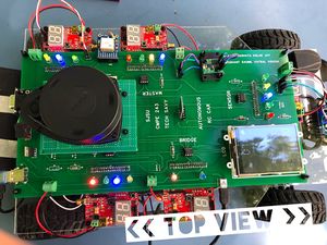
S19: Tech Savy
Contents
- 1 Tech Savy RC Car
- 2 Abstract
- 3 Introduction & Objectives
- 4 Team Members & Technical Responsibilities
- 5 Administrative Responsibilities
- 6 Team Deliverables Schedule
- 7 BILL OF MATERIALS (GENERAL PARTS)
- 8 Printed Circuit Board
- 9 CAN Communication
- 10 Hardware Design
- 11 LED Functionality in PCB
- 12 DBC File
- 13 3D printing models
- 14 Sensor Node
- 15 Motor Controller
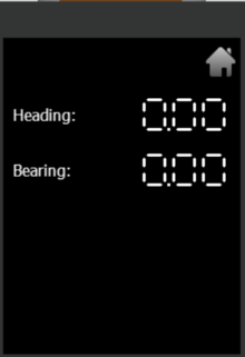
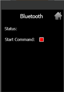
- 16 LCD Screens
- 17 Flow charts
- 18 Geographical Controller
- 19 Bridge Controller Communication
- 20 Master Module
- 21 Mobile Application
- 22 Suggestions for Future Students
- 23 Conclusion
- 24 References
Tech Savy RC Car
Abstract
In this project our main aim to build a Self-Navigating Car named Tech Savy, that navigates from a source location to a selected destination by avoiding obstacles in its path using sensors and motors.
Introduction & Objectives
The key features support by the system are
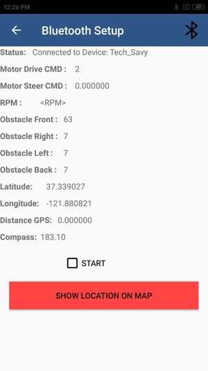
1. A Google-map based Android application is developed which will update the live location of RC car given by GPS to Bridge over Bluetooth.Android app is used to get information from all the Modules and will show live data of MOTOR, SENSORS, GPS and COMPASS and we can set the final destination so that car can drive to the destination.
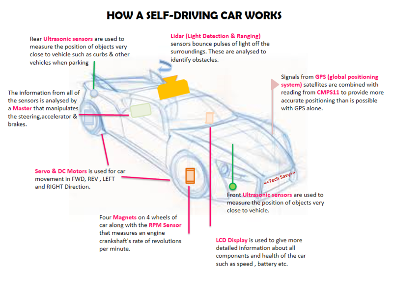
2. The car will be integrated with the GPS, Compass, Bluetooth, multiple sensors such as Ultrasonic sensors and RPM sensors to fulfill the purpose of navigation, obstacle detection, and avoidance
3. LIDAR and Ultrasonic Sensor is used for obstacle detection and avoidance in all the angles in the view of 360 degrees.
4. Motor drives the car by Route Calculation done on GPS using the shortest distance path algorithm between current location and destination and connects to the self-driving RC car via Bluetooth to send the GPS Coordinates and Maneuvering to the selected destination and Self- Adjusting the speed of the car on Ramp.
5. LEDs and LED Display are used for debugging and to get all relevant information about the status of the car, in real time and LCD Display is used to give more detailed information related to the car.
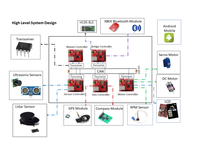
The system is built on FreeRTOS running on LPC1758 SJOne controller and Android application. The main building blocks of Tech Savy are the five controllers communicating through High Speed CAN network designed to handle dedicated tasks. The controllers integrate various sensors that are used for navigation of the car.
CAR Objectives
     1. Master Controller - Handles the Route Manuevering,Path Planning and Obstacle Avoidance
     2. Sensor Controller - Detects the surrounding objects
     3. Geo Controller - Provides current location in the form of coordinates and navigate car using CMPS11
     4. Motor Controller - controls the movement of the Car.
     5. Bridge controller - Interfaces the system using Bluetooth to an Android application.
Team Objectives
     1. Learn each and every module as much as possible, in order to develop an industrial product.
     2. Achieve 100% code coverage, during unit testing.
     3. Document and track all the bugs encountered during development, unit testing, and field testing.
Team Members & Technical Responsibilities
- Git Project Link: Tech Savy
- Master Controller
- Motor Controller
- Geographical Controller
- Sensor Controller
- Communication Bridge Controller
- Android Application
- LCD Interfacing & UI Designing
- Hardware PCB Integration
- Testing
Administrative Responsibilities
| Administrative Roles | ||||
|---|---|---|---|---|
|
Aakash Chitroda | |||
|
Halak Vyas | |||
|
Vatsal Makani | |||
|
Vidushi Jain | |||
|
Jay Parsana | |||
Team Deliverables Schedule
| WEEK |
START DATE |
END DATE |
TASK DETAILS |
STATUS |
|---|---|---|---|---|
| 1 | 26 Feb 2019 | 4 March 2019 |
|
Completed Completed Completed Completed |
| 2 | 05 March 2019 | 12 March 2019 |
|
Completed Completed Completed |
| 3 | 13 March 2019 | 19 March 2019 |
|
Completed Completed Completed Completed Completed Completed |
| 4 | 20 March 2019 | 26 March 2019 |
|
Completed Completed Completed Completed Completed Completed |
| 5 | 27 March 2019 | 09 April 2019 |
|
Completed Completed Completed Completed Completed Completed Completed Completed Completed Completed Completed Completed Completed Completed Completed Completed Completed |
| 6 | 10 April 2019 | 16 April 2019 |
|
Completed Completed Completed Completed Completed Completed Completed Completed Completed Completed Completed |
| 7 | 17 April 2019 | 23 April 2019 |
|
Completed Completed Completed Completed Completed Completed Completed Completed Completed Completed Completed Completed In Progress Completed Completed |
| 8 | 24 April 2019 | 30 April 2019 |
|
Completed Completed Completed Completed Completed Completed Completed Completed Completed Completed Completed Completed Completed |
| 9 | 1 May 2019 | 7 May 2019 |
|
Completed Completed Completed Completed Completed Completed Completed |
| 10 | 8 May 2019 | 21 May 2019 |
|
Completed Completed Completed Completed Completed |
| 11 | 22 May 2019 |
|
Completed Completed |
BILL OF MATERIALS (GENERAL PARTS)
| PART NAME |
PART MODEL & SOURCE |
QUANTITY |
COST PER UNIT (USD) |
|---|---|---|---|
|
|
|
|
|
|
| |
|
|
| |
|
|
| |
|
|
| |
|
|
| |
|
|
| |
|
|
| |
|
|
| |
|
|
| |
|
|
| |
|
|
| |
|
|
| |
|
|
| |
|
|
|
|
|
|
|
Printed Circuit Board
Design And Architecture
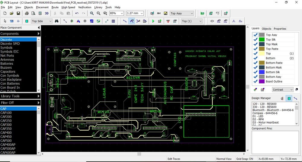
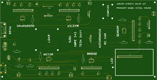
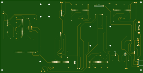
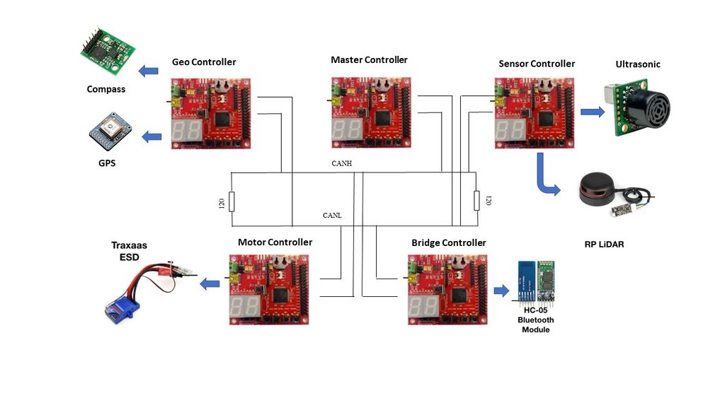
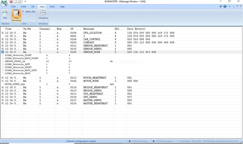
We designed the custom PCB using DipTrace Software in which we implemented connections for all the controller modules(SJOne Board LPC1758) all communicating/sending data via CAN bus. The data is sent by individual sensors to the respective controllers. GPS and Compass are connected to Geographical Controller. RPM sensor, DC and Servo Motors are connected to Motor Controller. Ultrasonic and Lidar are connected to Sensor Controller. LCD is connected to Motor Controller. Bluetooth is connected to Bridge Controller. CAN Bus is implemented using CAN Transceivers MCP2551 terminated by 120Ohms; with PCAN for monitoring CAN Debug Messages and Data.
Power Section
We implemented separate power modules for LIDAR and remaining modules of the PCB. The micro USB mini B supplies 5V to LIDAR Motor and Scanner (max current rating estimated @ 1A). Another power is supplied through USB 2.0 Type A connector with a rating of 5V@2A. Since GPS requires 3.3V, we have used a linear regulator REG1117-3.3. All the parts are through-hole components.
Fabrication
PCB was sent to fabrication to JLCPCB China which provided PCB with MOQ of 5 with the lead time of 1 week. We implemented 2 layers of PCB with most of the parts in top layer. We implemented rectangular header connector for SJOne boards, RPM sensor, DC & Servo Motor and GPS modules on the bottom layer.
Challenges
There were 2 iterations of this board. The first one was designed without validation and had problems with orientation of the SJOne board header & pin connections. We also need to change the header for LCD since it was having different pitch.This design lacked several necessary power connections and was limited by functionality. These problems were fixed in the 2nd iteration.
CAN Communication
- As the DBC file shows, master is given the highest priority after bridge start/stop command message.
- All messages from every controller are send to Bridge and Motor as well along with Master, to display it on Android app and LCD Controller for debugging and testing.
- Every controller is also sending Initialization Debug messages over CAN, to verify it on BusMaster.
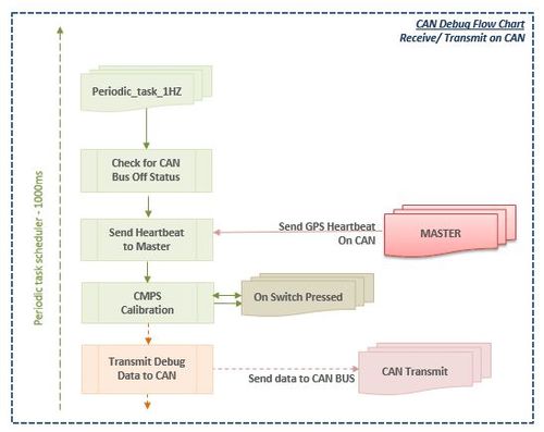
- 1Hz task is used to check CAN_bus_off() condition, along with send heartbeat and debug message messages over can.
- As master is the major receiver of all the signals, it perform MIA handling of all necessary signals along with heartbeat as well.
- We have also used plenty of LEDs for confirming we get correct heartbeat and data.
- The code for master MIA initialization is as shown below,
 const uint32_t                             BRIDGE_NODE__MIA_MS = 3000;
 const BRIDGE_NODE_t                        BRIDGE_NODE__MIA_MSG = { 0, {0} };
 const uint32_t                             SENSOR_NODE__MIA_MS = 3000;
 const SENSOR_NODE_t                        SENSOR_NODE__MIA_MSG = { 0 };
 const uint32_t                             GPS_LOCATION__MIA_MS = 3000;
 const GPS_LOCATION_t                       GPS_LOCATION__MIA_MSG = { 37.3686485, -121.9153289, {0} };
 const uint32_t                             COMPASS__MIA_MS = 3000;
 const COMPASS_t                            COMPASS__MIA_MSG = { 37.3686485, -121.9153289, 0.0, {0} };
 const uint32_t                             SENSOR_HEARTBEAT__MIA_MS = 3000;
 const SENSOR_HEARTBEAT_t                   SENSOR_HEARTBEAT__MIA_MSG = {0, {0}};
 const uint32_t                             MOTOR_HEARTBEAT__MIA_MS = 3000;
 const MOTOR_HEARTBEAT_t                    MOTOR_HEARTBEAT__MIA_MSG = {0, {0}};
 const uint32_t                             GPS_HEARTBEAT__MIA_MS = 3000;
 const GPS_HEARTBEAT_t                      GPS_HEARTBEAT__MIA_MSG = {0, {0}};
 const uint32_t                             BRIDGE_HEARTBEAT__MIA_MS = 3000;
 const BRIDGE_HEARTBEAT_t                   BRIDGE_HEARTBEAT__MIA_MSG = {0, {0}};
Hardware Design
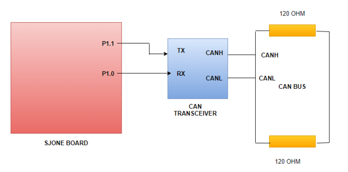
The CAN bus hardware implementation between all the controller module for this project is shown below. It is necessary to terminate the CAN bus at 120 Ohms to prevent any signal reflections.
We have implemented some LEDs for indicating the heartbeat signals sent by the master, sensor readings and motor movements. Below is the table explaining the LEDs in PCBs along with the color, pin and signal description
|
LED DESIGNATION |
GPIO PINS |
DESCRIPTION |
COLOR | ||||||||
|---|---|---|---|---|---|---|---|---|---|---|---|
|
VCC and GND | POWER | RED | ||||||||
|
P2.5 and VCC | RPM | RED | ||||||||
|
P0.29 | Motor Heartbeat | Yellow | ||||||||
|
P0.30 | DC Motor | Blue | ||||||||
|
P1.19 | Servo Motor | Green | ||||||||
|
P0.29 | Bridge Heartbeat | Red | ||||||||
|
P0.30 | DC Motor | BLUE | ||||||||
|
P0.30 | Geographical FIX | BLUE | ||||||||
|
P0.29 | Geographical Heartbeat | Yellow | ||||||||
|
P1.19 | Compass Data | Green | ||||||||
|
P0.29 | Sensor Heartbeat | Green | ||||||||
|
P0.30 | Left Obstacle | Yellow | ||||||||
|
P1.19 | Right Obstacle | Blue | ||||||||
|
P1.20 | Front Obstacle | Green | ||||||||
|
P1.19 | Right Obstacle | Blue | ||||||||
|
P0.29 | Sensor Heartbeat | Red | ||||||||
|
P0.30 | Motor Heartbeat | Green | ||||||||
|
P1.19 | Bridge Heartbeat | Yellow | ||||||||
|
P1.20 | Geographical Heartbeat | Blue |
|
LED DESIGNATION |
GPIO PINS |
DESCRIPTION |
COLOR | ||||||||
|---|---|---|---|---|---|---|---|---|---|---|---|
|
VCC and GND | POWER | RED | ||||||||
|
P2.5 and VCC | RPM | RED | ||||||||
|
P0.29 | Motor Heartbeat | Yellow | ||||||||
|
P0.30 | DC Motor | Blue | ||||||||
|
P1.19 | Servo Motor | Green | ||||||||
|
P0.29 | Bridge Heartbeat | Red | ||||||||
|
P0.30 | DC Motor | BLUE | ||||||||
|
P0.30 | Geographical FIX | BLUE | ||||||||
|
P0.29 | Geographical Heartbeat | Yellow | ||||||||
|
P1.19 | Compass Data | Green | ||||||||
|
P0.29 | Sensor Heartbeat | Green | ||||||||
|
P0.30 | Left Obstacle | Yellow | ||||||||
|
P1.19 | Right Obstacle | Blue | ||||||||
|
P1.20 | Front Obstacle | Green | ||||||||
|
P1.19 | Right Obstacle | Blue | ||||||||
|
P0.29 | Sensor Heartbeat | Red | ||||||||
|
P0.30 | Motor Heartbeat | Green | ||||||||
|
P1.19 | Bridge Heartbeat | Yellow | ||||||||
|
P1.20 | Geographical Heartbeat | Blue |
Implementation
Ultrasonic
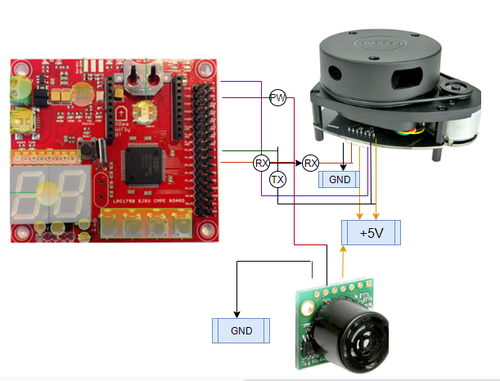
LV Maxsonar ultrasonic sensor is used at the very front of the RC car to provide wide range sonar detection ranging from 0 to 645 cm. It supports LiDAR sensor to detect very small obstacles like stone that can hinder car from moving forward. so we have purposefully mounted it at a lower level than LiDAR.
LiDAR
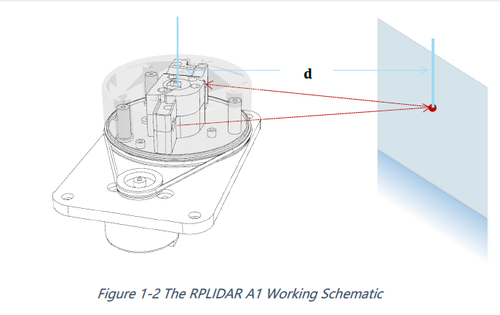
RPLidar works on UART. We have used UART 2 of SJOne Board to establish communication between them.
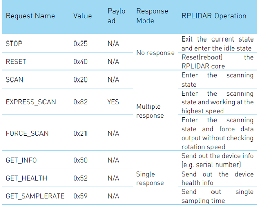
- Figure shows the several operation provided by RPLidar for better performance and reliable data.
Algorithm to establish communication through UART
- In order to start the scanning of Lidar, first send the 0X20 via
uart2.putchar(0x20). Before that, we can check the health status of RPLidar by sending 0x52. It waits for some time (timeout = 500ms), and if return status is not true throws error indicating Lidar is not initialized properly and hence it gets reset.
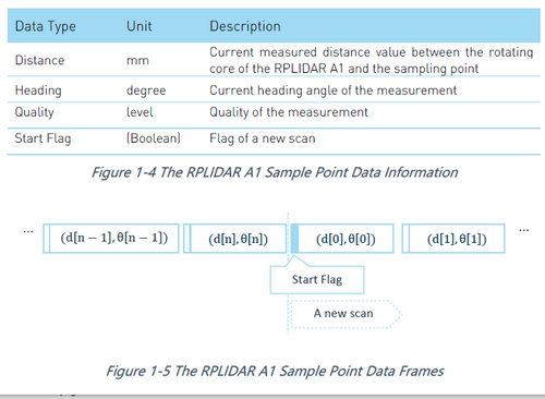
- As soon as correct scan command is received by Lidar, it starts sending data frames continuously on UART. The frame consists of 5 bytes including the start bit, Angle, quality and distance, which are useful to identify the exact position of obstacle.
- This data is processed and divided into tracks of 25 cm each.
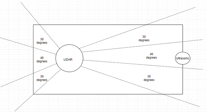
- By looking at the track, we choose the sector value which depends on angle detected. Below figure shows the division of angle for respective sector value.
- The obstacle information is sent to Master Node through CAN.
Software Design
Ultrasonic
- It works with the help of interrupt.
- After configuring GPIO pins as RX and TX, set RX pin high.
- PW pin gets the input, identify the type of interrupt
- Rising edge interrupt.
- Falling edge interrupt
- Calculate distance to obstacle,
-
ultrasonic_data.distance = (stop_time - start_time)/147;
-
LiDAR
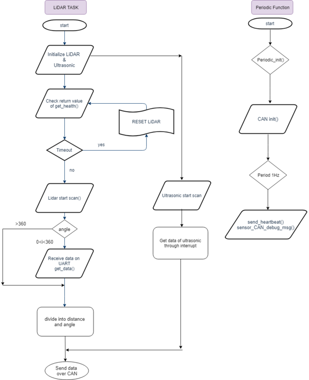
Below diagram shows the code flow of sensor module. A separate task was used to send sensor data over CAN, which continuously sends data in while(1) loop.
CAN DBC Messages Send from Sensor
  BO_ 105 SENSOR_NODE: 5 SENSOR
   SG_ SENSOR_FRONT_cm : 0|10@1+ (1,0) [0|645] "cm" MASTER,MOTOR,BRIDGE
   SG_ LIDAR_Obstacle_FRONT : 10|3@1+ (1,0) [0|0] "" MASTER,MOTOR,BRIDGE
   SG_ LIDAR_Obstacle_RIGHT : 13|3@1+ (1,0) [0|0] "" MASTER,MOTOR,BRIDGE
   SG_ LIDAR_Obstacle_LEFT : 16|3@1+ (1,0) [0|0] "" MASTER,MOTOR,BRIDGE
   SG_ LIDAR_Obstacle_BACK : 19|3@1+ (1,0) [0|0] "" MASTER,MOTOR,BRIDGE
   SG_ LIDAR_Obstacle_BACK_RIGHT : 22|3@1+ (1,0) [0|0] "" MASTER,MOTOR,BRIDGE
   SG_ LIDAR_Obstacle_BACK_LEFT : 25|3@1+ (1,0) [0|0] "" MASTER,MOTOR,BRIDGE
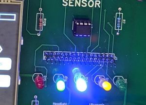
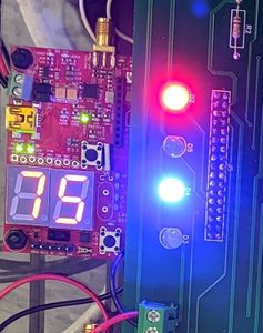
LED Blinking signals for SENSOR CONTROLLER ON CAR
* RED LED ON: MASTER HEARTBEAT STATUS on CAR
* BLUE LED ON: Obstacle detected at front of CAR
* Rightmost GREEN LED ON: Obstacle detected at right of CAR
* YELLOW LED ON: Obstacle detected at back of CAR
* Leftmost GREEN LED ON: Obstacle detected at left of CAR.
Technical Challenges
Ultrasonic
- When mounted initially on CAR, ultrasonic was giving sometimes faulty readings as it was detecting ground as and obstacle.
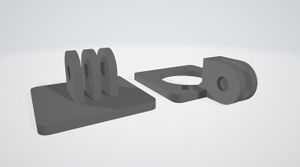
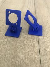
- We designed a 3D mount for it and adjusted it on such a angle that it gives perfect readings.
- Initialization issue: Sometimes on power-up we noticed that Ultrasonic sensor was giving faulty readings(it was getting stuck on some fixed value).
- After reading the datasheet accurately, I found that it calibrates itself during the first read cycle and so the obstacle should be at least 14 inches far from the sensor.
- Ultrasonic Failure - When the CAR got crashed, Ultrasonic sensor failed and started giving incorrect data.
- We replaced it's wired to get it working.
- We replaced it's wired to get it working.
LiDAR
- Identifying obstacle data and separating it.
- Initially I lost a lot of time in figuring out the data frame as it consists of quality, angle, distance and start bit.
- Dividing the frame bits appropriately and storing it separately in struct variables resolved the issue. Also after that depending on the angle, every 360 times data was fetched in a loop to cover each and every angle value.
- Task overrun because of receiving a large number of data continuously over UART.
- Used a separate task, that receives data continuously in a loop, i.e while(1).
- Instead of receiving whole data in a single frame, took data character by character in a for loop 360 times, to get the value of obstacle at each degree.
- Angle detection problem - When large angles were taken, for example, 30 degrees on the right, it was detecting nearer objects correctly but far objects were getting detected in some other range (for example in front instead of right) of angle because of angle spread. I divided the range into 10 degrees each and store it in the same variable to send it over CAN.
For example, to get 30 degrees in right, 0-10,10-20 & 20-30 values are taken. - Received variable initialization problem.
- I didn't initialize the character variable to get data from UART to 0 and hence it was taking garbage value.
Thanks to Preet, at time of my code review he pointed out this problem and later I checked it with Unit Testing.
- I didn't initialize the character variable to get data from UART to 0 and hence it was taking garbage value.
- Some bugs here and there in the code.
- I identified and resolved a few bugs after Unit testing the code.
- Delay in sending data because of large CAN buffer size.
- We were facing this issue with master, motor and sensor communication. The response time was slow as data was getting accumulated before sending because of large buffer size taken.
Motor Controller
Motor Controller is responsible to control the DC and Servo Motor, RPM Sensor measurements and LCD control. The motor control logic controls the steering and the speed of the vehicle using a servo and DC motor respectively based on the CAR_CONTROL_t CAN message from the master. It takes input from RPM sensor as a feedback for maintaining a constant speed and based on the RPM sensor reading, a PID loop calculates duty-cycle for PWM signal which are then given to DC motor. Based on other can messages from the sensor controller, geo controller and bridge controller, motor controller processes and communicates the information to the LCD by refreshing the data periodically in 10Hz function.
Hardware Design
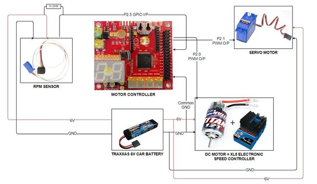
The hardware interface details of MOTOR Module with SJOne board are given below:
Hardware Interface
Electronic Speed Controller (ESC)
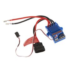
We made use of the Traxxas ESC XL-05 which comes with the RC car. ESC stands for Electronic Speed Control. It is used to control the DC motor using PWM signals from the controller. It powers up when we connect a LiPo or NiMH battery of 7.4v. The ESC has a dc-to-dc converter which converts 7.4v to 6v and provides it to DC motor. It can provide high current to the power hungry DC motors running at faster speeds. It has an LED and a button which is used for calibration and setting different modes for the car.
| S.No | Wires - ESC | Description |
|---|---|---|
| 1. | Positive wire (already Connected) | Connects to DC Motor positive |
| 2. | Negative wire (already Connected) | Connects to DC Motor negative |
| 3. | Positive Supply | Connects to supply of Li-Po battery |
| 4. | Ground Wire | Connects to ground of Li-Po battery |
| 5. | PWM input connected to P2.0 | PWM Signal From SJOne |
| 6. | Servo Vcc Supply | 6V power supply to power the servo |
| 7. | Common Ground | Negative terminal |
DC Motor
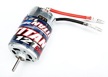
The DC motor is controlled using the ESC which get PWM pulses for controlling it. A PWM signal wire is connected to the microcontroller and the required current is provided by the LiPo battery and the ESC.
| S.No | Wires - DC Motor | Description |
|---|---|---|
| 1. | Positive Wire (already Connected) | Positive Terminal |
| 2. | Negative Wire (already Connected) | Negative terminal |
The DC motor is controlled using PWM at 100Hz.
| Operation | Pulse Width Range(ms) | Duty-cycle(%) |
|---|---|---|
| FORWARD | 1.51 - 2.00 | 15.1 - 20.0 |
| STOP | 1.50 | 15.0 |
| REVERSE | 1.00 - 1.49 | 10.0 - 14.9 |
NOTE: Before using the Traxxas ESC to give PWM signal to DC motor calibrate it by going to this website:
- The ESC must be given a pulse of 1.5ms when we turn it on or else the DC motor won't respond to PWM pulses.
- Step 1: Give 2.00ms on-time pulses when LED blinks red once.
- Step 2: Give 1.50ms on-time pulses when LED blinks red twice.
- Step 3: Give 1.00ms on-time pulses and the LED color changes from red to green showing that the calibration was successful.
Servo Motor
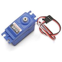
The direction the vehicle's front wheels turn is dependent on the servo motor in the vehicle. Based on various PWM signals, the servo steers the front wheels of the vehicle in the left and right direction. The servo has 3 wires of which one is for the PWM input signal whereas the other two are to power up the servo. We powered our servo motor using the 6v power supply from the battery elimination circuit present in the ESC so that a single switch to turn on and off both the servo and DC motor. PWM signals to control the servo is provided by the motor controller. Based on the PWM signal from the SJOne board, the shaft shall be rotated to a certain degree left or right
| S.No | Wires - Servo Motor | Function |
|---|---|---|
| 1. | PWM connected to P2.1 | PWM signal from SJOne board |
| 2. | VCC | 6V power supply from ESC |
| 3. | Ground | Common ground to system |
RPM Sensor
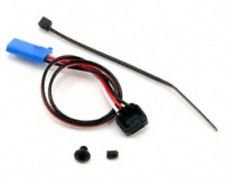
RPM sensor is used as a feedback element in the PID to maintain a constant speed of the vehicle. The RPM sensor mounts on the rear DC motor shaft compartment with a special assembly also provided by Traxxas. We make use of one magnet and we get one pulse on one wheel rotation The sensor works on the hall effect principle where it provides a current across its terminal when placed in a magnet's field. These pulses are read by the SJOne board and fed to the speed control algorithm. The RPM sensor has 3 wires, the white where are the output wire that provides the pulses to the SJone board and the other wires power the sensor.
Implementation
1. The idea is that every time the motor completes 1 whole revolution, it reaches very close to the sensor. And when the sensor detects the magnet nearby, it sends out a high pulse until the magnet moves away from it. Therefore, upon detecting the X number of a rising edge in Y seconds we can say that rpm was X revolutions/Y seconds.
2. During our initial testing of RPM Sensor with SJOne board, we saw that regardless of whether we bring the magnet close to the sensor or not, the signal voltage was always high. After some trail and errors, we found out that the signal pin(white wire) had to be connected to the VCC(red wire) across a 1K resistor which can act as weak pull down when it detects the magnet.
| S.No | Wires - RPM Sensor | Function |
|---|---|---|
| 1. | Signal wire connected to P2.5 | GPIO that supplies pulses to controller |
| 2. | VCC | 6V power supply from ESC |
| 3. | GND | Common ground |
uLCD32-PTU
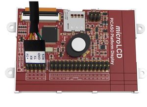
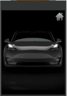
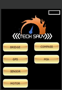
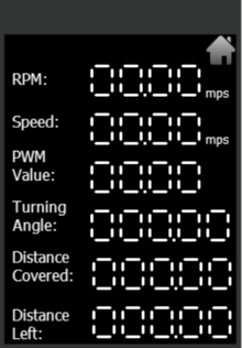
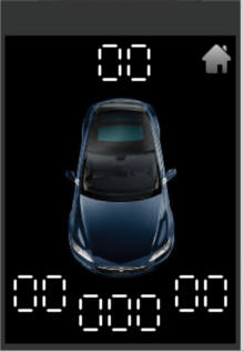
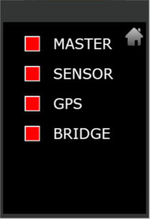
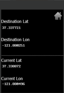
uLCD32-PTU by 4D systems has a 3.2" TFT LCD Display module. The module comes with a display resolution of 240x320 pixels. 4D Systems provides a programming cable based on UART for burning the LCD code to the module. The project is burnt to a uSD card which is used for display during booting of the LCD. It is recommended that we use the programming adapter provided by 4D systems as it has a special reset button that can be used to download the built project to the LCD display.Once the LCD display was configured with different widgets and screens, the motor module was coded to display information in LCD through UART. Workshop4 IDE was used to program the GUI, and data was transmitted from the SJOne board through UART communication. The LCD displays the main menu screen with options of all the modules: Sensor, Motor, Bridge, GPS, Compass and MIA information.
These modules represent the page numbers of the display whose information can be found from the pre-processed data format of the LCD.This data format contains the following fields:
- The write command
- Type of the object
- Object ID
- MSB and LSB values to be displayed in the LED.
- The last pair of hex value is for checksum.
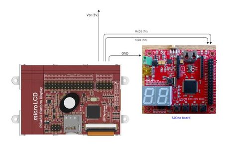
The following figure shows the programming cable and the pins used for uLCD32-PTU.
| S.No | Wires - LCD interface | Function |
|---|---|---|
| 1. | TX | Data Transmission connected to UART RX of SJ1 board |
| 2. | RX | Data Reception connected to UART TX of SJ1 board |
| 2. | VCC | Input 5v supply |
| 3. | GND | Common ground |
| 4. | RES | Reset Pulse(Not Required for our project) |
Software Design
The dc motor and servo motor operation is fundamentally based on PWM (Pulse Width Modulation). We set the PWM frequency to 100Hz for both dc and servo motor.
Pseudo code for initializing PWM to 100Hz.
PWM *motor_control;     //pointer object defined globally
PWM *servo_control;
void init_pwm(long unsigned int freq) {
    motor_control = new PWM(PWM::pwm1, freq);      // using PWM constructor to initialize the PWM 2.0 pin to desired frequency
    servo_control = new PWM(PWM::pwm2, freq);
}
DC Motor
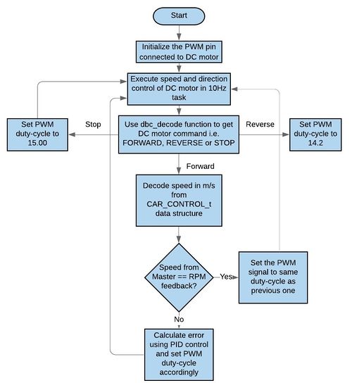
The DC motor is connected to pin P2.0 on SJONE board. The DC motor is commanded every 100ms to change or maintain its speed or direction(FORWARD, REVERSE and STOP). A switch case is used to check the command that we are receiving over CAN bus from master.
Pseudo code for dc motor and speed control
float speed = get_speed();
float _error = calculate_error_PID(drive_forward->MOTOR_mps, speed, &dc_motor);
*PWM_percent += _error
set_pwm_value(motor_1, *PWM_percent);
Servo Motor
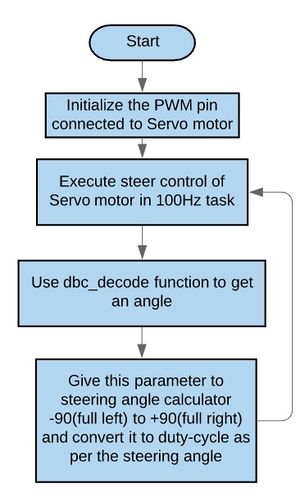
The Servo motor is connected to pin P2.1 on SJONE board. The servo motor is commanded every 10ms to change or maintain its angle between 0 and 180 degrees. We receive angle in the range of -90(full left), 0(neutral) and +90(full right) from master. The calculate PWM_duty_cycle_servo function maps the angle received from master to PWM signal and rotates the servo motor accordingly.
Pseudo code for servo motor and angle calculation
on_time = 10 + ((servo->MOTOR_STEER_cmd + 90) * (10/180));
set_pwm_value(servo_2, on_time);
RPM Sensor
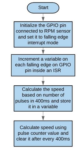
The RPM sensor is connected to pin P2.6 of SJONE board. When the wheel rotates once we get one pulse. We make use of interrupt to register these pulses in a 400ms time frame and then calculate the speed in m/s based on the formula:
speed_m_per_sec = (circumference * rotation_per_sec) / (constant);
After every 400ms we reset the pulse counter. We have an ISR which increments these pulses.
void eint3_handler(void){
    pulse++;
}
LED Blinking signals for MOTOR CONTROLLER
- RED LED ON: MASTER HEARTBEAT STATUS on CAR
- BLUE LED ON: Car is moving in reverse direction
- YELLOW LED ON: Car is stopped
- GREEN LED ON: Car is moving in forward direction
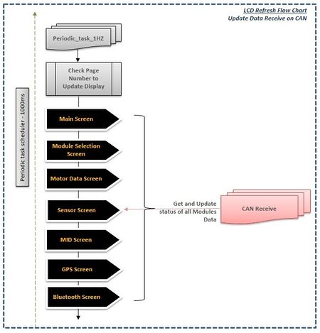
LCD Software Flow Chart
Programming SJONE Board for LCD Display
- As raw data often cannot be displayed on the LCD directly, the values to be displayed had to be converted to appropriate byte-sized values.
- Communication with SJOne board was established at the baud rate of 115200 bps.
- Commands for writing data and reading acknowledgment for various gauges were coded in the SJ1 board.
Creating a project using Workshop 4 IDE and programming the LCD display
- After finalizing the design of the LCD's layout, a genie project was created using Workshop 4.
- The layout was split into different forms (pages) and appropriate buttons and gauges were added for display.
- uLCD-32PTU was programmed with the help of programming cable provided by 4D systems.
The steps taken for interfacing the LCD display with the SJONE board is shown on the right:
Each of the reading is considered as a object with the object type ID and object number. Below are the list of objects used for lcd.
#define GPS_DEST_LATITUDE_OBJ        0
#define GPS_DEST_LONGITUDE_OBJ       1
#define GPS_CURRENT_LATITUDE_OBJ     2
#define GPS_CURRENT_LONGITUDE_OBJ    3
#define GPS_HEADING_OBJ              13
#define GPS_BEARING_OBJ              14
#define GPS_DISTANCE_OBJ             3
#define MOTOR_SPEED_MS_OBJ           8
#define MOTOR_PWM_OBJ                12
#define MOTOR_RPM_OBJ                4
#define MOTOR_TURNING_ANGLE_OBJ      9
#define MOTOR_DISTANCE_COVERED_OBJ   10
#define MOTOR_DISTANCE_LEFT_OBJ      11
So our approach was to send a LCDquery at 1Hz task using the below function.
void lcd_screen_query(void)
{
   char comm[] = {0, 0x0a, 0, 0x0a};
   for (int i = 0; i < (int)sizeof(comm); i++)
   {
       uart3_put_char(comm[i], 0);
   }
}
This query sends a a array of character to LCD and LCD acknowledges it and sends the pre-formated data to the controller using lcd_receive() called at every 10Hz. The receive() will contain the page number(lcd_screen) based on the screen it is currently into and prints the data corresponding to that screen i.e. GPS screen will call GPS_print function to print the GPS values.
void lcd_print()
{
   switch (lcd_screen)
   {
       case menu:
           lcd_print_menu_screen();
           break;
       case bridge:
           lcd_print_bridge_screen();
           break;
       case gps:
           lcd_print_gps_screen();
           break;
       case sensor:
           lcd_print_sensor_screen();
           break;
       case motor:
           lcd_print_motor_screen();
           break;
       case home:
           lcd_print_home_screen();
           break;
       case mia:
           lcd_print_mia_screen();
           break;
       case compass:
           lcd_print_compass_screen();
           break;
       default:
           break;
   }
}
LCD Screens
Flow charts
Technical Challenges
PWM frequency setting problem
- The PWM frequency won't set if we were making use of global objects directly using the SJONE PWM drivers. We verified using logic analyzer that our frequency was getting set to 1.19KHz instead of 100Hz.
PWM motor_control(PWM::pwm1, freq);
PWM servo_control(PWM::pwm2, freq);
- Solution: After trying out many things we made use of global pointer objects to solve the problem.
PWM *motor_control;     //pointer object defined globally
PWM *servo_control;
void init_pwm(long unsigned int freq) {
    motor_control = new PWM(PWM::pwm1, freq);      // using PWM constructor to initialize the PWM 2.0 pin to desired frequency
    servo_control = new PWM(PWM::pwm2, freq);
}
DC motor shooting randomly
- When we were testing our DC motor, we found that our dc motor would shoot randomly in forward and reverse direction when using GPP board. We checked our code and the entire wiring but were not able to fix it.
- Solution: When our PCB arrived we tested the DC motor on it and it worked fine. One suggestion would be to use the PCB as soon as possible as it won't waste your time on debugging unnecessary problems.
PID Calibration for uphill and downhill
- It uses an extensive amount of time to get the PID loop working which gives proper error values which maneuvers the car without stopping on uphill and controls speed during the downhill.
- Solution:You should start using PID for maneuvering uphill and downhill conditions from the beginning.
LCD Refreshing
- During testing the data received in LCD, we noticed that LCD was not getting refreshed quickly i.e even though PCAN dongle was updating data quickly but LCD was showing the data after a few seconds. At one point, the LCD stopped updating data.
- Solution:We used snprintf() for GPS and Sensor values.For Compass and Motor, we implemented MSB and LSB approach where lower 8 bits of data(int) was stored in LSB and upper 8 bits in MSB, followed by our custom display function lcd_put_comm() which converted the data to the pre-formatted data and displayed data over UART using uart_put_char(). Below is an example
   char msb,lsb = 0;
   int local_heading = gps_bearing * 100;
   lsb = (char)((char) local_heading & 0xff);
   msb = (char)((char) (local_heading >> 8) & 0xff);
   lcd_put_comm(WRITE_OBJ, LED_DIGITS, GPS_HEADING_OBJ, msb, lsb);
Geographical Controller
Geographical Controller is one the most important controller in the autonomous car which helps it to navigate to its destination. This modules continuously update the position and orientation of the car with respect to geographical north and send the data to Master, Motor and Android controller boards. We are using the Adafruit Ultimate GPS module and CMPS11.
- GEO CONTROLLER Git Link: [1]
Hardware Design
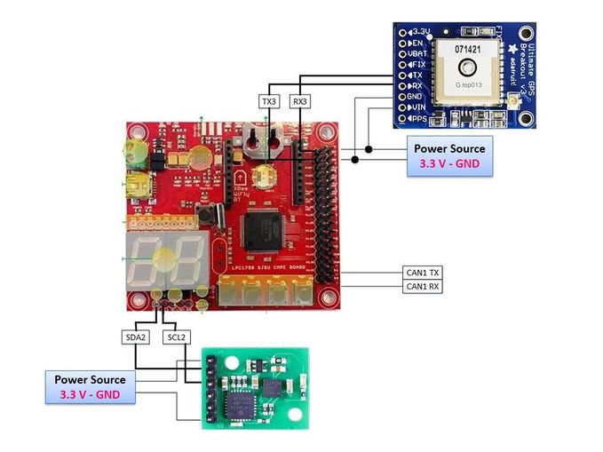
The hardware interface details of GPS and Compass Module with SJOne board are given below:
- LED Blinking signals for GEO CONTROLLER ON CAR
* RED LED ON: MASTER HEARTBEAT STATUS on CAR
* BLUE LED ON: Shows GPS FIX STATUS on CAR
* GREEN LED ON: COMPASS Data Indication
GPS
- GPS PinOut
* VCC: 3.3V Power
* GND: Ground
* TXD: Serial Transmit pin connected to RXD2 of SJOne board
* RXD: Serial Receive  pin connected to TXD2 of SJOne board
* FIX: States if GPS is fixed not
GPS is a global navigation satellite system that provides geolocation and time information to a GPS receiver anywhere on or near the Earth where there is an unobstructed line of sight to four or more GPS satellites.
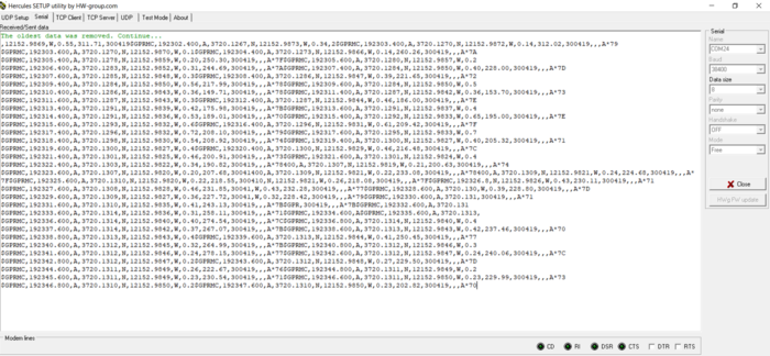
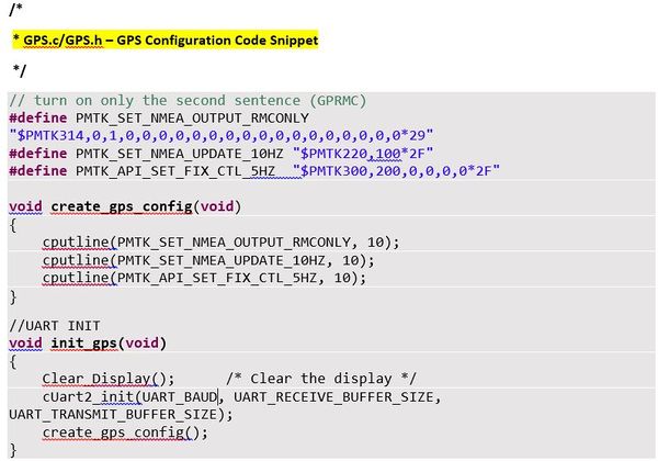
The GPS module used in this project runs on UART communication protocol. Its default baud rate is 9600bps and we are working on the same baud rate to extract GPS data. The GPS module works on NMEA 0183 standards which define the electrical and data specification for communication between the GPS module and its controller. We are using the Recommended minimum specific GPS/Transit data (GPRMC) command. It provides us with three important data which are Fix, Latitude, and Longitude, required for localization and navigation of the car. The update rate of these data from the GPS module is configured at 10Hz and 5Hz for fix control status.
- GPS Configurations:
GPS configuration Settings that we have used for the Adafruit GPS module is shown in the following picture. As per Arduino data-sheet, we can use different commands setting to set the different update rate from once a second (1 Hz) to 10 times a second (10 Hz) as per user requirements.
Compass
- Compass PinOut
* VCC: 3.3V Power
* GND: Ground
* SCL: Serial Clock pin connected to SCL of SJOne board
* SDA: Serial DATA pin connected to SDA of SJOne board
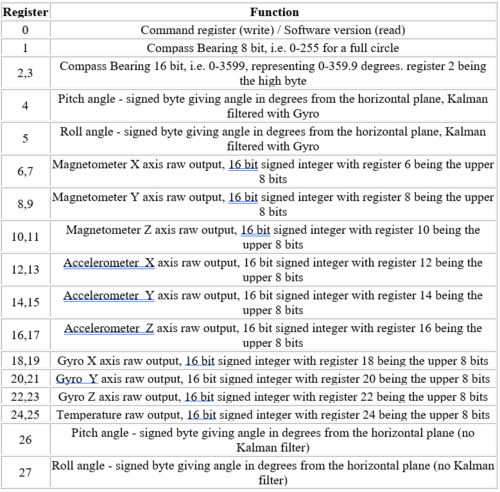
A Compass is an instrument used for navigation and orientation that shows direction relative to the geographic cardinal directions (or points). Compass is communicating over I2C with SJ One board. The register 2 and 3 of the compass provide the compass bearing angle (0- 360 range). Calibrating the compass is an important part. We are calibrating it on ‘horizontal calibration mode’, it works for us because the compass has tilt calibration.
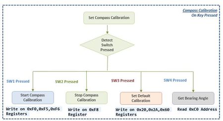
We are using the compass in I2C mode of operation. The following table on the left shows the registers and their functions and the software flow chart for getting/setting compass data and calibration on demand and We are using the Compass bearing (16-bit) given by the compass registers 2 and 3 to calculate our car heading.
Software Design & Implementation
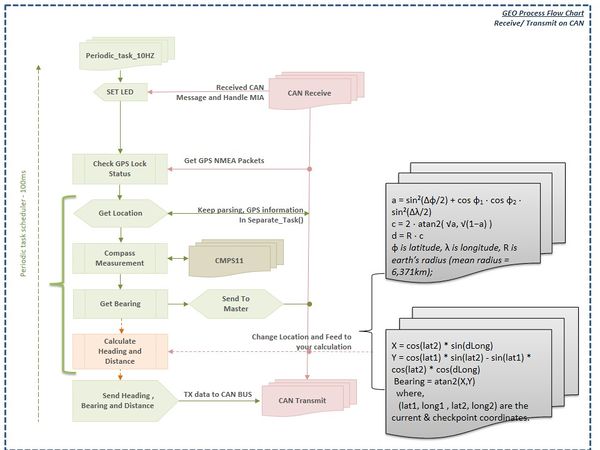
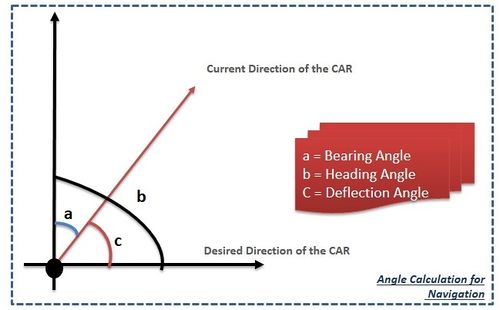
The Geographical Controller is in place for navigation purpose. It has two essential parts, namely GPS and compass. It provides direction to the car, by calculating the heading angle and the distance between the coordinates, based on GPS and compass readings. To calculate the heading angle, we need a compass bearing angle and angle between the line joining the two coordinates and the true north(bearing angle for GPS).
Distance between the two coordinates calculation
The distance between the two coordinates can be calculated using the Haversine formula.
 a = sin²(Δφ/2) + cos φ1 ⋅ cos φ2 ⋅ sin²(Δλ/2)
 c = 2 ⋅ atan2(√a, √(1−a))
 d = R ⋅ c
 where,
       φ1 = Latitude of 1st Coordinate
       φ2 = Latitude of 2nd Coordinate
       λ1 = Longitude of 1st Coordinate
       λ2 = Longitude of 2nd Coordinate
       Δφ = φ2 - φ1
       Δλ = λ2 - λ1
       d  = distance between the two coordinates
       R  = earth’s radius (mean radius = 6,371km)
 Note: All the angles should be in radians.
GPS Heading angle calculation
With reference to the figure, the Heading angle for GPS is the angle between the line joining the two coordinates and the true north. To calculate it graphically, draw a vector pointing towards the destination coordinates from the start point coordinate and measure the angle between the vector and the true north. Use the below formula to calculate the angle mathematically.
 Heading angle(α) = atan2(sin Δλ ⋅ cos φ2 , cos φ1 ⋅ sin φ2 − sin φ1 ⋅ cos φ2 ⋅ cos Δλ)
 where,
       φ1 = Latitude of 1st Coordinate
       φ2 = Latitude of 2nd Coordinate
       λ1 = Longitude of 1st Coordinate
       λ2 = Longitude of 2nd Coordinate
       Δλ = λ2 - λ1
The car reads the value of current coordinates from the GPS module to determine its Euclidean distance from the first checkpoint. It also checks the value on the compass to know which direction it should preferably move in i.e. Heading angle. The sensor readings help it ascertain that there isn't an obstacle to hinder its movement in the determined direction.
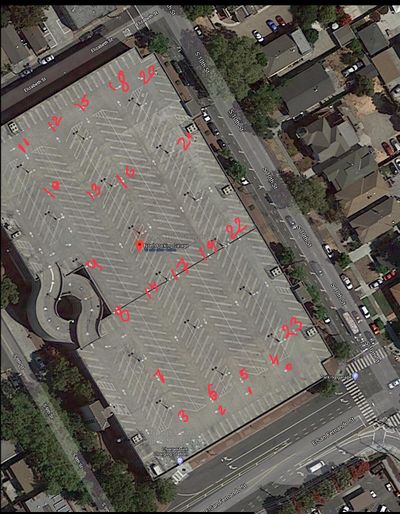
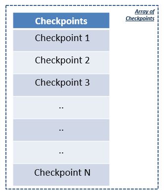
We have selected 23 checkpoints on the location where the demo is going to takes place and we have filled these coordinates in a Checkpoint Array as shown below.
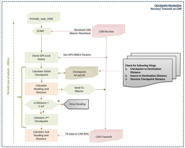
- The Car begins navigating its way from its current location to the final destination using enlisted checkpoints. When the car arrives at a first checkpoint, then GEO Controller will look into its GPS checkpoints constant array to look for next nearest checkpoint.
- While selecting Checkpoint we are using Linear Searching technique to select next checkpoint which is closer to the current location and as well as closer to the final destination.
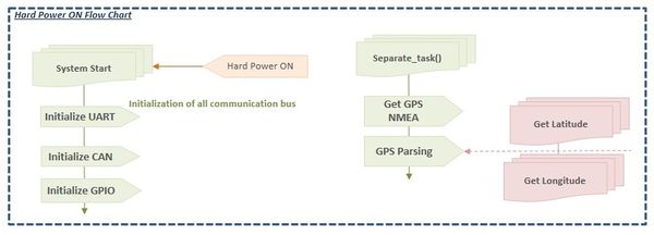
The Software state machine flow chart for GPS Navigation is shown below:
Technical Challenges
- Issues 1 - GPS doesn’t retain configuration settings; GPS module was forgetting its baud setting of 57600bps configuration settings after a long run testing of GPS module(we kept GPS for overnight testing to capture logs of GPRMC to check its location consistency) before the implementation of Distance calculation so after 4-5 hours its start giving Null values for latitude and longitude after reviewing the logs of the data captured that was giving garbage data as UART baud mismatching gives then it has to be configured again that means baud rate setting using PMTK command.
Solution - As per recommendation is given in Arduino Data sheet we should use default baud settings of 9600 later we never faced this issue and it was giving a good fix.
- Issue 2 - One of the most important thing with GPS is to get a quick fix. Our First Time to fix was coming approx 50seconds even in the open sky which is not good for self-driving car the moment engine of the car turns on we should have Coordinates of the car to navigate this to the destination location. So first Time to fix was one the hurdle for us.
Solution - We have followed one of the Arduino Forum in which one of the experts give few tips on how to improve this GPS Fix issue and one of the tips worked for us was the of the Cell battery with the voltage of more than 2.89v. This resolves GPS fix the issue for us.
- Issue 3 - Compass frequently losing its calibration when we were using CMPS11 in calibrated Mode.
Solution - Using CMPS11 in default calibration mode helped us to get rid of this problem
- Issue 4 Ahhhh!! Faced task overrun issue with GPS NMEA data. When we were using NMEA parsing and shortest path algorithm in one task or even in two different tasks code was crashing like anything. However, NMEA parsing and Path Finding algorithm were working fine.
Solution - Preet's easy parsing function(using sscanf) and his advice of using separate task using FreeRTOS helped us resolving this problem.
- Issue 5 During parsing of GPS Coordinates we have faced one issue with data type Float. Due to can transmission, we were using float data type for Latitude and longitude and what we have noticed that after getting data in string/char* and converting it to float then last two-three decimal places of latitude and longitude were changing frequently due to which Calculated distance from SOurce to destination was changing randomly even car is sitting at one location.
Solution - GPS coordinates require double datatype so, we took coordinates as double and then while sending data on CAN we were typecasting that to float. As we were doing all calculation related to coordinates, distance and checkpoints calculations on GEO Controller itself. So after doing all the calculations in double, we were type casting data to float and we were sending that to MASTER & BRIDGE.
Bridge Controller Communication
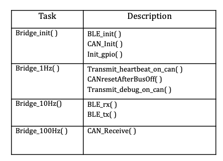
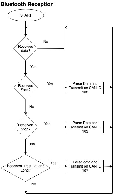
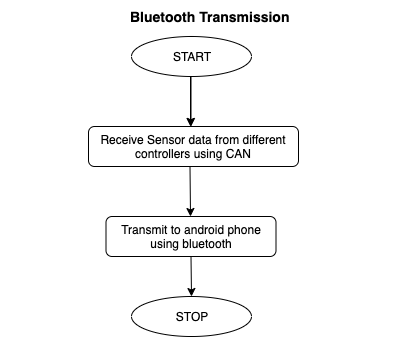
Bridge Controller is used for communication between the SJOne board and the android phone using the HC-05 Bluetooth module. The main purpose of the bridge Controller is to receive the start/stop command and destination location from the Android app. Bridge controller will transmit all the sensor information and debug information and this information will be displayed on the android app.
- BRIDGE CONTROLLER Git Link: [2]
Hardware Design
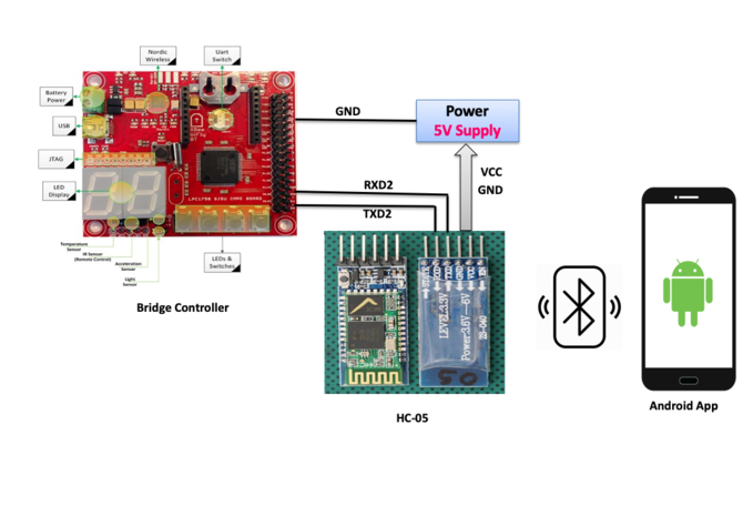
Bluetooth Module Hardware Interfacing:
We are using an HC-05 Bluetooth module to send and receive the data from our android application to Controller. The Bridge controller is connected to the Bluetooth module through the Serial interface(UART2) of SjOne board and we have configured HC-05 at 38400 baud rate 8-bit data and 1 stop bit using modules Communication Mode. Bridge Controller is connected to other SJOne Boards using CAN bus. The Bluetooth module communicates with the SJOne board using UART communication at 38400 baud rate.
HC-05 Bluetooth module
HC-05 Bluetooth Module is used to set up wireless communication between the Car and the Android phone. This module is based on the Cambridge Silicon Radio BC417 2.4 GHz BlueTooth Radio chip. This is a complex chip which uses an external 8 Mbit flash memory It includes the Radio and Memory chips, 26 MHz crystal, antenna, and RF matching network. The right section of the Bluetooth Board has connection pins for power and signals as well as a 5V to 3.3V Regulator, LED, and level shifting.
- HC-05 PinOut
* EN:  In a case brought HIGH before power is applied, forces AT Command Setup Mode
* VCC: 5V Power
* GND: Ground
* TXD: Serial Transmit pin connected to RXD2 of SJOne board
* RXD: Serial Receive  pin connected to TXD2 of SJOne board
* STATE: States if connected or not
- LED Blinking signals
* Flashing RED Fast: Ready for Pairing with nearby Bluetooth device available
* Flashing RED Slow: Paired and Connected
Software Design
Technical Challenges
- Android App was crashing due to the parsing function when there was no GPS data coming from the Bluetooth module. To solve this problem we added checks in the bridge controller to not to send GPS data if the GPS is not yet fixed.
- Bridge controller's task was getting overrun when used snprint and printf in a task. (printf was just used for initial testing).Then after debugging, we found this problem and removed printf. snprintf and sprintf are working fine in 100Hz function.
Master Module
Hardware Design
Design and Implementation
- As name suffice, Master Node acts as the brain of the RC car and gives controlled signals to every other module.
- It manages the communication among all the modules, including Motor, Sensor, Geographical and Bridge Controller.
- Master receives periodically data from CAN bus based on message ID of the sender module.
- Below shows the connection of Master module on the CAN bus, connected with CAN Transceiver.
Software Design
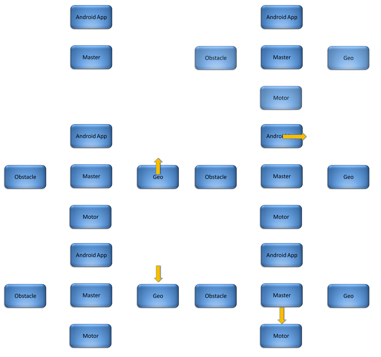
- As the Master takes all the decisions, it has the highest priority and hence the lowest message Id on CAN DBC.
- Figure illustrates the high-level bus flow from master to every module.
Implementation
Heartbeat Message of All Modules
- As Master node handles all the communication from other modules, each node continuously sends its heartbeat to master, confirming that it is active and working properly.
- If all the heartbeats are not received by the master, it sends STOP command to bridge so CAR doesn't run into a stage when any one of a node is not working. This mechanism provides us to eliminate running into an error state.
- If the heartbeat is not received, Master handles this using MIA.
- Code below displays heartbeat synchronization and MIA handling of all nodes.
  bool hbt_sync_from_all_node(void)
  {
    is_hbt_sync_flag = sensor_hbt_sync & motor_hbt_sync & gps_hbt_sync & bridge_hbt_sync;
    return is_hbt_sync_flag;
  }
  void master_mia_handler(void)
  {
    if (dbc_handle_mia_SENSOR_HEARTBEAT(&sensor_hbt, 25))
    {
       sensor_hbt_sync = false;
    }
    if (dbc_handle_mia_MOTOR_HEARTBEAT(&motor_hbt, 25))
    {
       motor_hbt_sync = false;
    }
    if (dbc_handle_mia_GPS_HEARTBEAT(&gps_hbt, 25))
    {
       gps_hbt_sync = false;
    }
    if (dbc_handle_mia_BRIDGE_HEARTBEAT(&bridge_hbt, 25))
    {
       bridge_hbt_sync = false;
    }
  }
Testing and Technical Challenges
- Delay in sending steer command to the motor.
- Initially there was some delay observed while receiving the sensor obstacle information and sending relevant command to motor, because of this synchronization problem we were suffering from the delayed response.
- After plenty of hardware and software debugging, we noticed the buffer size of CAN RX/TX was much larger than required. It was corrected on sensor and motor side as well.
- Taking time in reversing even though the reverse command was send
- Motor took time to reverse as it has to break it's PID loop.
- The solution to this was to send a stop command(0), before sending the reverse command.
<Bullet or Headings of a module>
Improper Unit Testing
- The problem of CAN buffer described above was detected by Unit Testing itself.
- Along with that bug, I found few more bugs from unit testing the code.
Mobile Application
Software Design
1. Enable Bluetooth and Connect to bridge controller
Wireless communication with the car takes places with communication over Bluetooth protocol. Android Application is created which provides an interface to exchange data and configure the car parameters.
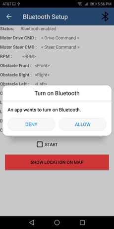
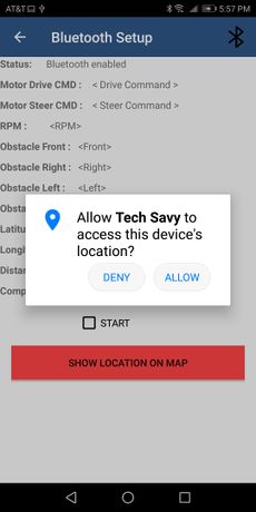
The android app connects to the HC-05 BLE module of the bridge controller. The Bluetooth ask the user for permission to access location and prompts to enable Bluetooth if it's already OFF. Our app is designed to connect to only TechSavy Bluetooth module and no other Bluetooth device to ease the setup of Bluetooth communication. A Bluetooth adapter connects to the HC-05 module and opens a Bluetooth Socket over which read and write messages are sent. A thread runs in the background which checks for available data, reads it and the data can then be processed. Data is written via the same Bluetooth socket. Refer to the following link to get started with Bluetooth on Android app and connection to HC-05 module ([3]).
2. Start/Stop Command and Log Sensor values
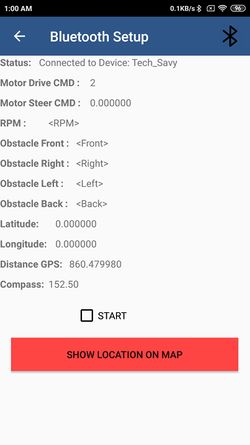
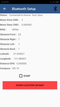
Start and Stop commands are sent to the RC car via the application. When Start/Stop button is pressed 1 or 0 commands are sent to the bridge controller when then transmits it to the CAN Bus for processing. Bluetooth status, Sensor Values, Motor parameters, GPS location, compass heading angle, distance to the checkpoint is displayed for debugging purpose. Sensor, GPS, motor Messages coming from CAN bus are decoded by the bridge controller and sent to the Android application as a string. The android app parses the string and categorizes the data to store it in appropriate variables. The data is then displayed as a text view in Bluetooth activity. To visit the Map Activity for setting destination and checkpoints a button is added. The map Activity opens on pressing the button.
3. Map Activity
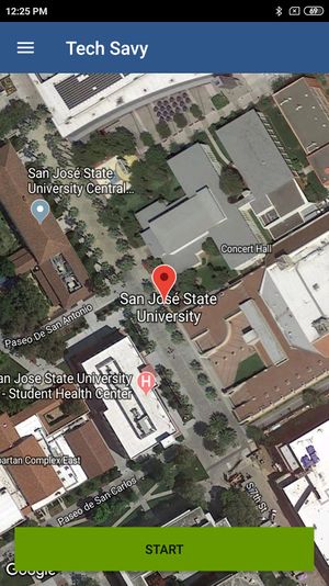
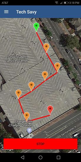
The map activity is used in our app to show the current location of the car and set the destination marker which the car will navigate too. When map loads in the app the cars current location is indicated coming from the GPS as the source location (Red Marker). The desired location on the map can be set as the destination by long clicking on the map (Light Green marker). The destination can be changed as desired by long pressing again. When the start button is pressed command 1 is sent to the CAN bus via Bluetooth to start the car. A thread starts in the background to indicate the current position of the car when the car moves (light blue marker). Also, a polyline is drawn between the source and destination marker to indicate the direction in which the car will move. For adding Google map to app refer the following [4](Refer to Maps and geolocation section)
Testing and Technical Challenges
1. We faced the problem of adding Bluetooth functionality in the app. There is a lack of tutorials online which shows how to develop an android app with Bluetooth capability and communicating with the HC-05 module. Fortunately, we found this webpage [5] which helped us and Youtube videos of Coding with Mitch.
2. It was difficult to design the UI on the app with little java and Android experience. We designing UI from mainly two resources [6] [7]and searching online for problems faced by us.
3. Initially, we developed the app such that we had to manually connect to a paired device to use Bluetooth functionality. This gave us problems while sending commands to the bridge controller. We solved this problem by fixing the device connection only to our HC-05 module and adding only a single Bluetooth connection button on the app bar for Bluetooth connection.
4. When we received too many sensor values and debug messages from the bridge controller continuously, the app was crashing due to the input buffer overflow. We solved this problem by adding a 1000ms sleep time to limit the input data coming to the app.
5. There was a requirement to continuously update a marker on the map indicating the current location of the car for user feedback. We achieved this using a thread in the background which updated cars position every 1 second.
Suggestions for Future Students
- For Master Controller
- Don't make your obstacle avoidance complex by implementing reverse condition. Just keep your code simple.
- One good approach a developer should follow is to unit test their own code. Would you buy a product which is suppose to be tested later?
- Remember the KISS approach when you code. (Keep It Simple and Stupid).
- For this controller, one should know the basics in C/ C++ and some good debugging skills. Because if you don't have one, you will eventually end up spending more time debugging your problem.
- For Hardware Team
- Order Hardware and Components as early as possible.
- Select components wisely don't try to save money on this part of the project as bad quality hardware can't help you even with best software implementation.
- Try to power up all modules using 6V coming from LiPo battery. Use IC boosters for converting 6V to 5V and 3.3V. This way there won't be a need of separate power bank and overall weight will be reduced.
- While designing PCB keep the tracing width of power lines to 1 mm so that sufficient current can be pass through it.
- PCB spacing should be 12-15 mil.
- To reduce the magnetic interference from DC Motor, place the compass on the center or near the front side of the car at a height using standoffs.
- Another alternative to standoffs could be implementing ground rings for compass and GPS Antenna which allows passing the EMI directly to the ground.
- Get more samples of CAN transceiver IC's as it can get damaged easily.
- For SENSOR Controller Team
- LIDAR - It has some limitations when tests/demo takes place in bright sunlight. when direct light falls on it, so gives faulty readings.
- LIDAR Consumes more power, hence need a separate power source for it due to which battery consumption of overall CAR is double as compared to the CAR use ultrasonic sensors for obstacle detection.
- LIDAR is not even cost effective hence should use Ultrasonic instead we realized it very late.
- Sensor Implementation doesn't need any averaging or complex algorithms.
- For GEO Controller Team
- Suggestions for GEO Controller software development is used FreeRTOS separate Tasks instead of using periodic tasks for NMEA receiving and parsing.
- For GPS Checkpoint navigation use simple and stupid coding no need to implement Dijkstra and complex algorithms for short distance calculation on Geo Controller linear or binary searching technique is enough to implement it successfully.
- For Compass use default calibration mode no need to add any checks and calibrations. Factory mode should be enough to get accurate results.
- For Motor Controller Team
- Use global pointers while using PWM drivers of SJONE board and set the frequency appropriately before testing it on motor(50Hz or 100Hz is fine).
- Calibrate the ESC first for any RC car you purchase and get that right or the DC motor wont work.
- Clear the CAN buffer periodically or the car might react to the commands with some delay.
- Tips for getting GOOD Grades and to remain in top 3 teams
- Select your team mates wisely, and make sure every one dedicates them self for this project.
- Be an active member of your team and review rubrics every week before going to demonstrate your CAR.
- As soon as the professor mentioned about the project please start working on the project right from the beginning otherwise at the end you have struggled with finals and you will be left with less time for testing and you have to struggle in demo.
- Although you can get lots of information from seniors still don't take this project light this is a really interesting and challenging project.
Conclusion
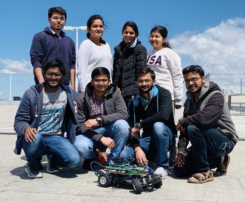
It was a really great working experience for all of us. We were really thrilled from the beginning that we will work on something that is quite relevant in the industries these days. We worked as a team of 8 which helped us all to know the importance of team-work and co-ordination. We learned much great stuff like
- CAN bus communication,
- LIDAR, ultrasonic sensors,
- PCB designing, GPS, Compass, Android Application development.
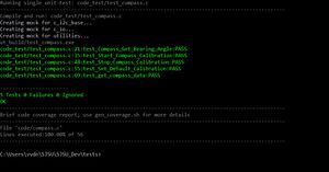
- Unit testing with 100% coverage accelerated our development significantly and it helped us to get great results in less amount of time.
- We also learned how to debug and interpret CAN message using BusMaster.
- Git also plays an important role to maintain the source code. There were a lot of problems while doing this project but it was a steep learning curve. In the end, we were able to achieve our objective with really good results.
Project Video
- Git Project Link: Tech Savy
References
Acknowledgement
We would like to express our gratitude to Professor Preetpal Kang for generously sharing his time and knowledge with us and guiding us through the completion of this project. We would also like to thank the Pratap(ISA) for their valuable advice and constructive feedback.
References Used
LIDAR
PID Control
LCD
Android GUI
Google Maps
Datasheets
[1] XL-MaxSonar-EZ4 Ultrasonic Sensor
[2] 4D Systems LCD
[3] CAN Transceiver
[4] GPS Module
[5] Compass Module
