F13: Quadcopter
Contents
Grading Criteria
- How well is Software & Hardware Design described?
- How well can this report be used to reproduce this project?
- Code Quality
- Overall Report Quality:
- Software Block Diagrams
- Hardware Block Diagrams
- Schematic Quality
- Quality of technical challenges and solutions adopted.
Quadcopter
Abstract
The Quadcopter is a four rotor remote controlled aircraft. It takes in remote commands from a hobbyest remote control, and achieves steady flight by utilizing a 3 axis accelerometer and a 3 axis gyroscope to determine the current attitude. It then takes the values from the remote control, and current attitude, and determines the needed changes to the motors to achieve the desired flight.
Objectives & Introduction
Objectives
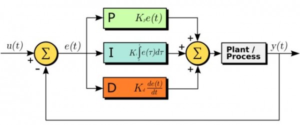
The objective of this project is to build a remote controlled quadcopter that is capable stable flight. We will control the quadcopter via a Spektrum DX5E hobbyist controller. We will be creating an Inertial Measurement Unit(IMU) using a 3 axis accelerometer and a 3 axis gyroscope. The IMU will communicate with the SJ One Board via I2C. We will be implementing a complementary filter in software to estimate the quadcopter attitude, and will then have a PID control loop in software to generate outputs to the motors.
Introduction
Before we get started, we must first define a few aircraft terms, and describe how they are manifested on the quadcopter.
Aircraft Motion Primer
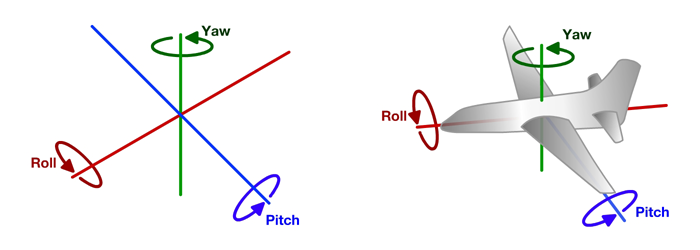
The motion of an aircraft can be described by three types of motion: Roll, Pitch and Yaw.
Roll is the rotation of the aircraft around the x axis and makes the aircraft turn left and right. Pitch is rotation about the Y axis, and in an airplane causes the aircraft to climb and dive. On a quadcopter, the pitch controls going forward and backward. Yaw is defined by rotation about the Z axis.
On a quadcopter, two of the rotors move in a counter-clockwise motion, and two move in a clockwise motion. The opposite rotation will allow for flight without uncontrollable yaw due to the angular momentum of the motor/propeller assemblies canceling each other out. Vertical motion is controlled by the motor speed for all rotors. Moving forward/backward is caused by pitching forward or pitching backward. To pitch forward, speed up the rear prop, and slow down the front prop. To pitch backward speed up the front rotor, and slow down the back rotor. To roll left, speed up the right rotor, while slowing down the left rotor. To roll right, speed up the left rotor, while slowing down the right rotor. To Yaw right, speed up both the left and right rotors, while slowing down the front and back rotors. To yaw left, speed up the front and back rotors, and slow down the left and right rotors.
Team Members & Responsibilities
- Craig Farless
- Airframe Design
- Sensor Design
- Remote Control Interface Design
- Flight Controller Software Design
Schedule
| Task | Projected Completion Date | Actual Completion Date | Status | Notes |
| Buy Parts | 1-Oct | 1-Oct | Complete | |
| Build frame | 8-Oct | 8-Oct | Complete | |
| Install Sensors | 15-Oct | 8-Oct | Complete | |
| Code I2C i/f to sensors | 15-Oct | 15-Oct | Complete | |
| Code Filters | 22-Oct | 15-Oct | Complete | More filtering may be needed |
| Code accel/gyro conversion to angle | 22-Oct | 22-Oct | Complete | |
| Integrate Power System | 22-Oct | 22-Oct | Complete | |
| Code PWM input | 29-Oct | 15-Nov | Complete | Much more difficult than planned |
| Code cmd translator | 29-Oct | 20-Nov | Complete | |
| Code PID | 5-Nov | 17-Nov | Complete | Will continue tuning PID |
| Code PWM Encode Driver | 12-Nov | 16-Nov | Complete | |
| Integrate Processor with Aircraft | 12-Nov | 1-Nov | Complete | |
| Tether Testing 2D stabilization (pitch, roll) | 19-Nov | 30-Nov | Complete | More sensor filtering and PID tuning may be needed |
| Tether Testing 3D stabilization (pitch, roll, yaw) | 26-Nov | - | - | Went directly to Flight Testing |
| Full Flight Testing | 26-Nov | 3-Dec | Initial Testing | More flight testing required |
| Demo | 3-Dec | 3-Dec | Complete | |
Parts List & Cost
The table below summarizes the parts used and the cost for the Quadcopter project.
| Qty | Description | Manufacturer | Part Number | Total Cost |
|---|---|---|---|---|
| 4 | Electric Speed Controller (ESC) | Castle Creations | 010-0125-00 | $148.00 |
| 4 | Park 480 Brushless Outrunner 1020kV motor | E-Flight | EFLM1505 | $180.00 |
| 1 | Triple Axis Accelerometer Breakout - ADXL345) | Sparkfun | SEN-09836 | $27.95 |
| 1 | Tri-Axis Gyro Breakout - L3G4200D | Sparkfun | SEN-10612 | $49.95 |
| 1 | Triple Axis Magnetometer Breakout - HMC5883L | Sparkfun | SEN-10530 | $14.95 |
| 1 | SJOne Board | SJSU | - | $75.00 |
| 1 | Logic Level Converter Bi-Directional | Sparkfun | BOB-12009 | $2.95 |
| 1 | Quad 2 Input Or Gate | On-Semiconductor | MC14071BCP | $2.25 |
| 1 | DX5E 5 Channel 2.4Ghz Tx/Rx Remote Control | Spektrum | DX5e | $89.99 |
| 1 | 4000mAH 25C 3S Lipo battery | Hyperion | - | $45.00 |
| 5 | EC5 male and female connector | Hobby King | - | $20.00 |
| 1 | Black Silicon coated wire 12AWG 1 meter | Hobby King | - | $5.00 |
| 1 | Red Silicon coated wire 12AWG 1 meter | Hobby King | - | $5.00 |
| 1 | 12x24 Aluminum Treadplate (0.063) | Home Depot | - | $34.78 |
| 2 | 1/2" Aluminum Trim Channel, 4' | Home Depot | - | $22.54 |
| - | Misc Nuts and Bolts | Home Depot | - | $30.00 |
| Total Cost | $753.36 |
Design & Implementation
Hardware Design
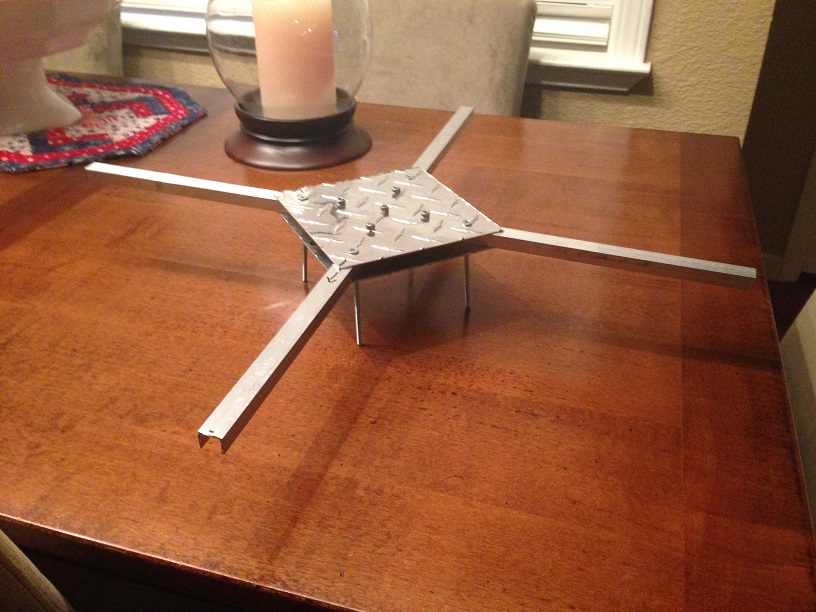
The quadcopter consists of two main groups: the airframe, and the flight controller subsystem. The airframe consists of arms of 1/2 inch aluminum trim channel arms, sandwiched by 1/16 inch aluminum diamond plate. The assembled airframe is show below.
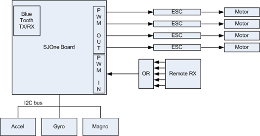
The quadcopter project flight controller subsystem block diagram is shown below. The major components are the SJ One board, the remote RX, the quad 2 input or gate, the accelerometer, the gyroscope, and the magnetometer, the 4 ESC modules, and the motors connected to the ESCs.
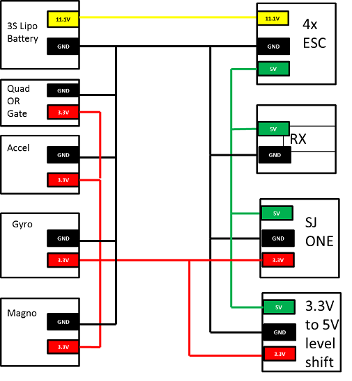
The quadcopter power distribution diagram is shown below. All power comes from the on board 3S 4000mAh 25C Lithium Polymer battery. The battery puts out 11.1V nominal, and the ESC takes in the 11.1V and outputs a 5V output for use by the rest of the flight controller. The SJ One board takes in the 5V and creates 3.3V to be used by the rest of the components.
Hardware Interface
PWM In From Remote Ctrl
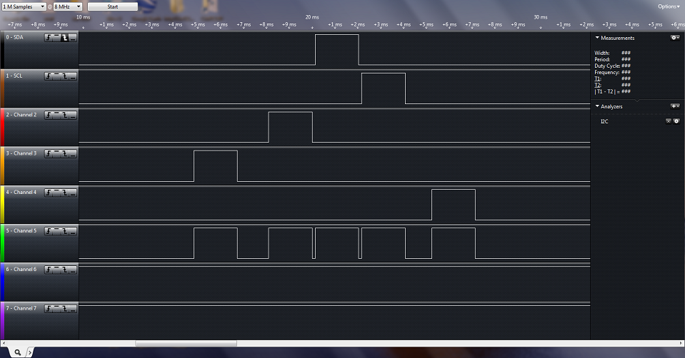
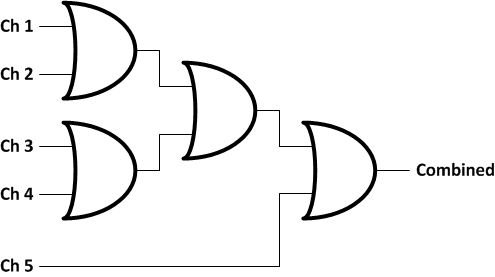
The DX5e on board receiver outputs 5 channels of PWM input running at a 50Hz refresh rate. The voltage levels of the PWM in are 5V. The SJ One board is not 5V tolerant, and there are not 5 channels of input capture pins available. In order to get the values requested by the remote control, one needs to translate the voltage levels to 3.3V, and to try to combine the signals to a single input. After researching on line, an example design was found that took the 5 channels of input and or'ed all of them together to get a single pulse train out. The example design also suggested a 5V tolerant part that would output 3.3V. After investigating the hardware that is used on the Quadcopter project, it was decided that this could work. A logic analyzer capture of the receiver output is shown below, as well as the output of the or gate. As is shown, the pulse train does not overlap, so the or gate is sufficient to handle both the level shift to 3.3V and the combining of signals.
Below is a logical representation of how the or gate is wired.
PWM Out
Quadcopters by nature need fast refresh rate on current position, and need low latency thru the control loop to actual commands to the motors. To help keep the latency low, the output PWM was ran at a faster than normal rate. The output PWM is running at 400hz instead of the normal 50hz refresh rate. The minimum pulse width is approx 1ms and the maximum pulse width is about 2 ms.
I2C Sensor Bus
The sensors all run off of a single I2C bus. The accelerometers base address is 0xE5, the magnetometer base address is 0x48, and the gyroscope base address is 0xD3. The I2C bus clock rate is 400kHz to help minimize the control loop latency.
Software Design & Implementation
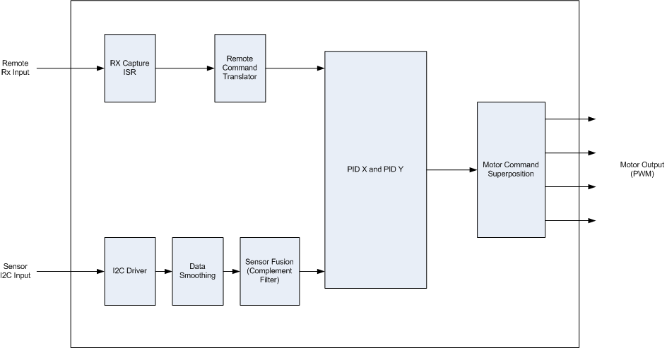
The top level software block diagram is shown below. The quadcopter project utilized free RTOS to help with scheduling. The following sections will go into the details on each block shown.
RX Capture ISR
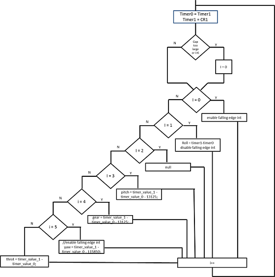
The PWM input is connected to Capture pin CAP1.1 on gpio P1.19. The CAP input is setup to trigger an interrupt on each rising edge and each falling edge of the input PWM pulse train. The TIMER1_IRQHandler is setup to give a semaphore to get_remote_ctrl_values task, and then quickly clears the current interrupt. The get_remote_ctrl_values task is shown in the block diagram below.
Remote Command Translator
I2C Driver
Data Smoothing
Due to vibrational noise, an additional lowpass filter was added before the sensor fusion and after the I2C input. The filter acts on the raw sensor data after it has been scaled correctly. The code for the filter is quite simple:
smoothed_value = smoothed_value + alpha * (input - smoothed_value);
There is very little latency thru the filter, and it really seemed to help with data noise.
Sensor Fusion
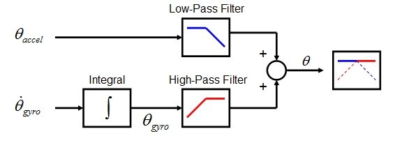
Sensor fusion is the act of taking reading from two or more sensors, and combining them in a meaning full way. Sensor fusion is used in this case because we are taking data from a noisy accelerometer, and from a gyro scope that shows accumulated error on readings over a long time (more than a sec). We combine them such that we are taking the stable instantaneous values from the gyro and combining them with the stable over a long period values from the accelerometer. We manage this via a Complementary Filter. A complementary sends the angle values from both the accelerometer and the gyroscope and low pass filters the accelerometer,and high pass filters the integrated angular velocity from the gyroscope. See the figure below.
This function can be implemented in a couple of lines of code for each axis.
// Complementary Filter Implementation
filtered_angle = (A)*(filtered_angle+gyro_rate*dt);
filtered_angle += (1-A)*acc_angle;
There is a complementary filter for both the X and the Y axis. It was decided as the project was winding down to not implement yaw control due to schedule constraints. When there is time, there will be a complementary filter taking in gyro values and values from magnetometer to measure yaw and feed that into an additional PID stage.
PID
PWM Out
The error values out of the PID section are applied directly to the PWM pulse width math. See the code below:
           motor_front_sum = throttle_in +  error_in.errorX;
           motor_back_sum  = throttle_in + -error_in.errorX;
           motor_left_sum  = throttle_in +  error_in.errorY;
           motor_right_sum = throttle_in + -error_in.errorY;
Note, what was added to one half of front/back is subtracted from the other half. Same holds true for the left/right pair. The design also has limitations of pulse widths min and max to make sure not to disable the motors. If the throttle in + error is larger than the max value for pulse width, it clips at the max value. The same is true if throttle in + error is less than min pulse width. It holds the minimum value.
Testing & Technical Challenges
Testing
The first testing attempted was I2C read/write testing. Once the sensors were wired up, a quick while loop with a delay was implemented to show that the sensors could be read reliably.
The next portion of testing was the PWM input testing. This took a while to get right due to ISR issues. Once the ISR was working, it was possible to printf the pulsewidth values calculated and compare to what the input controls were set to.
To test the ability to run the motors correctly, a test task was created that would drive the motors at 25%, 50%, 75%, and 100% depending upon which button on the SJ One board was pressed.
The angle calculation for X, Y, and Z was tested by having the data_smoothing task print to the console 1 time out of every 100 calculations. The test consisted of holding the quadcopter in my hand and rotating it around each axis and watch the value of angle match the correct sign, as well as test if the magnitude was in the correct ballpark.
Once the angle calculation seemed correct, the feedback loop was closed by adding in the PID with a guess of the values. To do this testing, we attached the quadcopter between two saw horses so that it could only rotate in a single plane. The majority of testing was of this type. PID gain values were tested until the X axis was quasi stable. We then switched to the Y axis and set the PID gains to the same values. After fixing some sign errors, and other math errors, we were able to make the Y axis mostly stable as well.
The final bit of testing attempted was flight testing. This testing showed that we need to make sure to implement the yaw control. Once the quadcopter lifted off, it started to yaw, which made it hard to fly correctly.
Technical Challenges
One of the largest technical challenges found was getting the PWM input ISR to not crash the processor, and to operate correctly. After long hours of debugging it was found that there was a low level driver that was using the same timer interrupt. Once this was solved, the development went a lot smoother, and we were able to reliably receive the commands from the remote control, and have the flight control software act upon these commands.
The largest technical challenge found is only partly overcome. There seem to be some issues with the data coming out of the sensors. In an attempt to clean this up, there was some additional data smoothing added to both the gyro output and the accel output. This did help the stability of the flight correction, but there are still issues.
Another technical challenge found was the process of tuning the PID gain values. This will continue to be a work in progress until the sensor reads are clean and accurate.
Conclusion
The quadcopter was a very challenging project. While I was not able to achieve the stable flight I had been hoping for, the quadcopter did fly. The project was a great learning experience. I learned a lot about the LPC1758. I learned a lot about interrupt service routines. I learned a lot about IMU's and flight control software. I learned a lot about how to implement and tune a PID control loop.
The next steps for the quadcopter project will be to continue attempting to clean up the data from the sensors. There may be some issues with noise and or discontinuities. This will be facilitated by getting data logging to the mico SD card working. I will then be able to characterize any data problems off line via matlab, and target filtering and or changes to sensor reads to fix the issues.
Project Video
Upload a video of your project and post the link here.
Project Source Code
References
Acknowledgement
I would like to acknowledge and thank my patient wife for putting up with all the time spent on the project.
I would like to acknowledge and thank Brandon for loaning me his logic analyzer.
I would like to acknowledge and thank Rob for lending me his RC expertise, and answering all of my silly questions.
I would like to acknowledge and thank Preet for the help with the ISR issues encountered and his teaching an interesting class.
References Used
http://nicisdigital.wordpress.com/category/quadcopter/
http://web.mit.edu/scolton/www/filter.pdf
http://theboredengineers.com/2012/05/the-quadcopter-basics/
http://theboredengineers.com/2012/05/the-quadcopter-part-1-genesis-of-the-project/
http://www.instructables.com/id/RC-Quadrotor-Helicopter/?ALLSTEPS
http://blog.oscarliang.net/quadcopter-pid-explained-tuning/
Appendix
You can list the references you used.
