F18: Spartan Warrior
Contents
Grading Criteria
- How well is Software & Hardware Design described?
- How well can this report be used to reproduce this project?
- Code Quality
- Overall Report Quality:
- Software Block Diagrams
- Hardware Block Diagrams
- Schematic Quality
- Quality of technical challenges and solutions adopted.
Project Title
SPARTAN WARRIOR
Abstract
This project involves creating a shooting game, with increasing levels of difficulty, as the user progresses. The point of the game will be to shoot all of the enemies on the LED screen and avoid getting shot by them. If all enemies are shot within the allotted time, then the user will progress to a higher level, where there will be more enemies. The user will be given 3 lives. After 3 deaths, the user will have to start a new game, in order to play again.
Objectives & Introduction
Team Members & Responsibilities
- Alisha Jean Patrao
- Game Design and Firmware, PCB
- Andrew Kwon
- Soundtrack, LED Matrix Driver Development and LPC1758 Integration
- Samir C. Mohammed
- Wiki Management, PCB, LED Matrix Driver Development and LPC1758 Integration, Game Design and Firmware
- Sanjana Gowda
- Game Design and Firmware, PCB
- Tanmay Chandavarkar
- Controller Design and Integration, Soundtrack
Headline text
Schedule
| Week# | Date | Deliverables | Status |
|---|---|---|---|
| 1 | 10/8 |
|
|
| Week# | Date | Deliverables | Status |
| 2 | 10/16 |
|
|
| Week# | Date | Deliverables | Status |
| 3 | 10/23 |
|
|
| Week# | Date | Deliverables | Status |
| 4 | 10/30 |
|
|
| Week# | Date | Deliverables | Status |
| 5 | 11/06 |
|
|
| Week# | Date | Deliverables | Status |
| 6 | 11/13 |
|
|
| Week# | Date | Deliverables | Status |
| 7 | 11/20 |
|
|
| Week# | Date | Deliverables | Status |
| 8 | 11/27 |
|
|
| Week# | Date | Deliverables | Status |
| 9 | 12/4 |
|
|
| Week# | Date | Deliverables | Status |
| 10 | 12/11 |
|
|
| Week# | Date | Deliverables | Status |
| 11 | 12/19 |
|
|
Parts List & Cost
| Part | # | Cost | Source |
|---|---|---|---|
| LPC 1758 Development Board | 2 | $160.00 | Preet |
| Adafruit 32 x 32 LED Matrix | 1 | $39.95 | https://www.adafruit.com/product/1484 |
| PCB | 1 | $23.00 | https://www.pcbway.com/ |
| eBoot Mini MP1584EN DC-DC Buck Converter | 1 | $7.99 (6 pack) | https://www.amazon.com/gp/product/B01MQGMOKI/ref=oh_aui_detailpage_o00_s00?ie=UTF8&psc=1 |
| 5V/4A Power Supply US plug | 1 | $15.95 | https://www.amazon.com/gp/product/B0749668H2/ref=oh_aui_detailpage_o01_s00?ie=UTF8&psc=1 |
| 2.1mm Female Barrel Jack | 1 | $5.79 (2 pack) | https://www.frys.com/product/7726878?site=sr:SEARCH:MAIN_RSLT_PG |
| VS1053 Codec + MicroSD Breakout - v4 | 1 | $24.95 | https://www.adafruit.com/product/1381 |
| Mini Portable speaker AUX interface | 1 | $16.99 | https://www.amazon.com/gp/product/B01NAFNT1M/ref=oh_aui_detailpage_o00_s02?ie=UTF8&psc=1 |
Design & Implementation
Hardware Design
SANJANA(LPC 1758, LED Matrix, Power Circuit and PCB) / ANDREW(mp3 hardware interfacing with decoder and LPC)
Discuss your hardware design here. Show detailed schematics, and the interface here.
Interfacing the LPC 1758 and the Adafruit LED Matrix...
PCB...
MP3 Decoder...
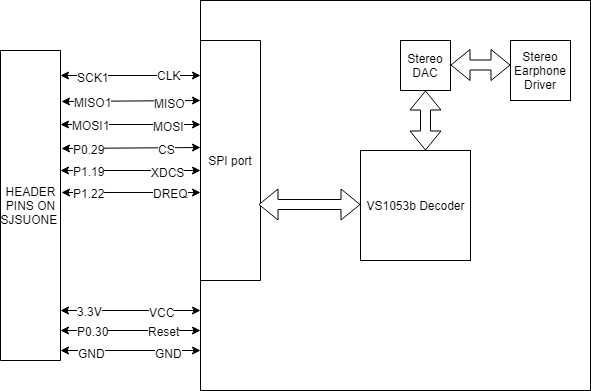
The SDCS pin on the VS1053b decoder is not used, because transfer of Mp3 file data is done using the SD card on the LPC 1758 micro-controller.
A total of 9 pins are used, in order to implement communication between the Mp3 decoder and the micro-controller; 6 Pins for SPI transfer(SCLK, MISO, MOSI, XDCS, CS, DREQ) and 3 pins for VCC, GND, and Reset. The CS pin is used to read and write to registers on the Mp3 decoder.
The XDCS pin is used to transfer data directly to the decoder, in order to output sound.
Another significant pin, is the DREQ pin. DREQ is the only input signal to the LPC 1758 micro-controller from the Mp3 decoder. The purpose of this signal is to alert the decoder and signal that 32 bytes of the Mp3 file are ready to be decoded. When DREQ is low, an SPI transfer to the decoder should not take place. This may be because the previous SPI transfer has not finished.
Hardware Interface
SANJANA(LPC 1758, LED Matrix, Power Circuit and PCB) / ANDREW(mp3 hardware interfacing with decoder and LPC)
The project consists of a 32x32 LED Matrix,SJSU ONE Microcontroller for game control, Portable USB Power Supply, MP3 Decoder, Speaker,SJSU ONE Microcontroller for driving the MP3, PCB,Shooting switch as shown in the Fig(1).The Microcontroller boards are powered up using the Portable USB Power Supply. One is used for game control and other one is used for driving the MP3 Decoder. The two boards communicate with each other using a GPIO pin.It helps in signalling the board handling the Mp3 task as to when to start and stop the sound track. The GPIO Pin is set high when the game begins so that the board handling the mp3 can start playing the sound track in the queue in order and the GPIO pin is set to low when the game is over and hence the board stops playing the sound track.An external switch is used for shooting the enemy sprites.
Fig(1)Sparatan Warrior System Design
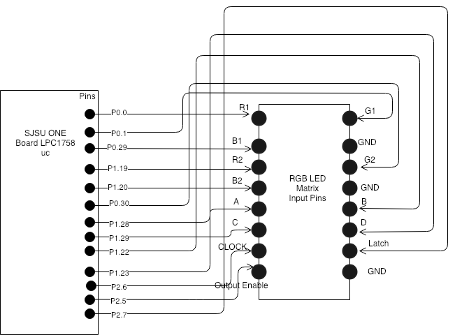
The Fig(2) depicts the Interfacing of RGB LED Matrix to the SJSU One Microcontroller Board.Since there was no datasheet available it was difficult to figure out the interfacing of the LED matrix and we started writing the driver on our own. The Adafruit has a few tutorials on their website about the pins based on which we made the connections.The RGB LED Matrix consists of 6 Data Pins(R1,G1,B1,R2,G2,B2) and 3 control pins (Clock, Output Enable, Latch) and 4 row select pins( A,B,C,D) and 3 GND pins.The LED Matrix is powered using a 5V/2A power supply adapter .The Pins of the microcontroller board are connected to the LED matrix using the connectors.The GND pins are both board and the matrix are connected on the bread board.
Fig(2)Interface of RGB LED Matrix to SJSU ONE Board
Software Design
ALISHA(game code) / ANDREW(mp3 code)
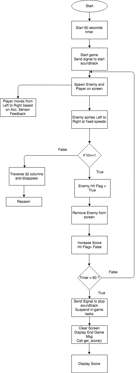
When the system is powered up the start_screen() task executes, displaying a welcoming message. All in-game tasks are suspended except for start_screen() and iterate_through_LED_matrix_rows_start_end() (which controls the LED matrix's row multiplexer's and 6 shift register's inputs/outputs. The led matrix illuminates, displaying the message “ Spartan Warrior starts in 3..2..1..”, with a 1 second delay between the countdown.
Thereafter, all in-game tasks are resumed and a GPIO signal is sent to another SJOne Board that starts the soundtrack. The game_over() task starts a 60 second timer, which sets the time that the player has to score points during the game.
When the game begins, the enemy sprites and the player sprite, populate the screen. The player sprite has one dimension of movement (left and right), governed by feedback from the LPC 1758's acceleration sensor Y-axis tilt output. The enemies traverse the screen from left to right, moving one column of pixels at a time. Their spawn time is controlled by a random number generator and a unique scalar modulus value. This is used to set random delays in between spawning. If an enemy sprite laterally traverses the matrix without being hit, it is removed from the screen (upon reaching the 31st column of pixels) and re-spawns on the left side of the matrix after a random delay.
When an enemy sprite is hit by a projectile (fired by the player), a "hit flag" is set. This triggers a sequence where the enemy sprite is removed from the virtual LED matrix array and the player's score is increased by a set value. Each enemy sprite has a different "score value", depending on how difficult it is to hit them.
Once the 60 seconds time elapses, the game_over task suspends all in-game tasks. It sends a signal to the SJOne board that controls the soundtrack, letting the board controlling the mp3 player know to stop playing the soundtrack. A "Game Over" message is displayed and the get_score() function is called, which displays the player's final game score.
The game code utilizes 14 tasks that are managed by the FreeRTOS task scheduler. All tasks have equal priority, so the scheduler executes them in a round-robin manner. The description for each of these tasks is as follows:
 Task : Draw_start_screen   |    Priority: 1

          Set score = 0;
          Suspend all in-game tasks;

 while(1)
          Display Welcome Message
          Send GPIO signal (1) to SoundTrack SJOne Board;
          Resume all in-game tasks;
 Task: iterate_through_led_matrix_rows_start_end        |    Priority: 1


 while(1)
        if (row % 16 == 0)
               M.Buf = 0;
               Row = 0;
        else
                if ( values of A,B,C,D) // row mux control
                    set LED shift register input values
              pull clock low;
              pull latch low;
          set output enable high;
Task : iterate_through_led_matrix_rows | Priority: 1
 Task: draw_enemy_1   |    Priority: 1

 Generate enemy by srand(0)

 while (1)
         if (column >= 31 or hit_flag_1)
               Enemy_1 disappear;
           If (hit_flag)
               Score+=1;
               Hit_flag = false;
         else
               Enemy traverse through columns;
Task: draw_player_sprite | Priority: 1
 Task:  move_player_sprite   |    Priority: 1

            acceleration_sensor_step_value = 75;

            while(1)
                     AS_prev_curr_compare = previous_AS_value - acceleration_sensor_feedback_Y;
                     if( acceleration feedback value)
                          player moves to the desired direction;
 Task : fire_a_shot   |    Priority: 1

 while (1)
           if(   ---------- )
              if(________________)
                       projectile_path(column);
Task: detect_a_hit | Priority: 1
 Task: Get_score    |    Priority: 1

 Set 60 second delay timer.
 Send stop signal to Soundtrack SJOne board
 Suspend all in-game tasks.

 while(1)
         Display endgame message.
         Call get_score()
         Display score.
(Board 1)Main:
init SPI master clock to 24Mhz
reset MP3 through reset pin
init MP3 registers (SCI_CLOCKF, SCI_MODE, SCI_AUDATA, SCI_BASS, SCI_VOL)
Task: readSong    |    Priority: 1

Check if SPI Bus is taken
    if (taken)
        do nothing
    else
        read 4k bytes from file and send to Queue

Task: playSong    |    Priority: 2

Check if SPI Bus is taken
    if (taken)
        do nothing
    else
        store 4k bytes into array from Queue
        for(128 iterations)
           send 32 bytes to MP3 decoder
Implementation
TANMAY / ANDREW(mp3)
- This section includes implementation, but again, not the details, just the high level. For example, you can **list the steps it takes to communicate over a sensor, or the steps needed to write a page of memory onto SPI **Flash. You can include sub-sections for each of your component implementations.
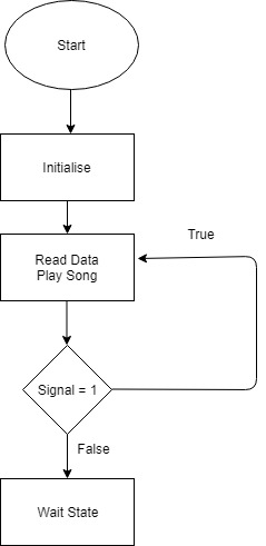
The system basically maps down to two LPC1758 boards, one controlling the LED Matrix and the other that reads soundtracks from an SD card using SPI. The two boards communicate with each other using a GPIO pin. This helps in signalling the board handling the mp3 tasks to start and stop the music. The GPIO pin is set when the game starts which gets the audio decoder to collect the data from the queue and play it on the speaker connected at the output. When the game reaches the end, the GPIO pin is reset which signals the decoder to stop retrieving data from the queue. The code uses the following to get the data from the SD Card and insert it in the queue:
Storage::read("1:track1.mp3", &dataChunk[0], 4096, songoffset); songoffset is a data member that stores the starting address of 4k bytes to send to the queue.
The in-built Acceleration Sensor present on the SJOne board is used to move the avatar. The corresponding header file which is included in the setup package is used to get the Y-axis coordinates.
Testing & Technical Challenges
SAMIR
Developing a driver for the LED matrix...
The biggest technical challenge that we faced was interfacing the LPC 1758 micro-controller, with the Adafruit 32 x 32 LED matrix.
Adafruit (the 32 x 32 LED matrix's manufacturer) provides a basic tutorial on their website, in order to help with interfacing the LED matrix to a micro-controller. The tutorial briefly describes the functions of the pins on the board's input and output connector ports. It also describes how to connect jumper wires to the ribbon cable (which comes packaged with the board), which connects to the matrix's input and output connector ports. It assumes that the user will utilize an Arduino-type micro-controller to drive the matrix's RGB LED's.
Because we used the LPC 1758 to drive the LED matrix, our choices were to either adapt a third party driver library designed for an Arduino, or develop a new driver. We chose the latter option, as the third party Arduino-focused API's were difficult to fully understand. We also felt that developing our own driver would allow us to gain a strong understanding of all aspects of micro-controller to LED matrix integration. This proved useful both for firmware development and debugging.
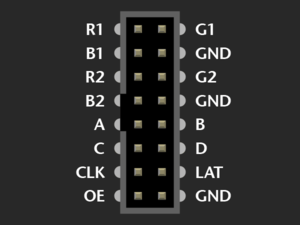
The first part of developing the LED matrix driver, was learning how each of the 16 input pins affected the matrix display.
The LED matrix's input socket looked as follows:
GND...
The 3 GND pins were the easiest to understand. They provided a ground signal reference for the matrix's RGB LED's. The GND pins on the LED matrix were connected to GND on the LPC 1758, through a ground plane on the PCB, allowing the micro-controller and LED matrix to share the same signal reference.
A B C D...
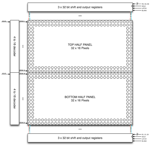
Pins A, B, C and D, were used as control bits for the LED matrix's row multiplexer. The 32 x 32 matrix is made up of two individual 16 x 32 LED panels. Each panel contains 16 rows and 32 columns. The binary values of the multiplexer signals, A, B, C and D, are used to determine which row of LED's is being driven. Each panel drives the same row of LED's at a time, based on these values. For example, if A, B, C and D are set to 0000, then the LED's in the first row of each panel can be driven. If A, B, C and D are set to 0001, then the LED's in the second row of each panel can be driven. This pattern continues until A, B, C and D are set to 1111, which corresponds to sixteenth (bottom) row of each panel. We set our row iterating value, as i = (i + 1) % 16, so that A, B, C and D, would be set to 0000, after finishing latching data into the sixteenth row. This allowed the multiplexer to continuously loop through each row in each panel, from top to bottom. We applied a delay of 1ms after each row iteration, thereby setting the overall scan rate to 62Hz. This scan rate was too fast for the human eye to detect, which allowed the LED matrix to display objects steadily, without annoying flickering compromising the image quality.
R1 B1 G1
R2 G2 B2...
Pins R1, B1, G1 and R2, B2, G2, were the 6 control signals used to drive the matrix's RGB LEDs, different combinations of red, blue and green (depending on their binary values). R1, B1 and G1, controlled indiidual LED colors on the top panel (panel 1), while R2, B2 and G2, controlled individual LED colors on the bottom panel (panel 2). The way these color combinations manifested on the board, were as follows:
| R | B | G | COLOR |
| 0 | 0 | 0 | OFF |
| 0 | 0 | 1 | GREEN |
| 0 | 1 | 0 | BLUE |
| 0 | 1 | 1 | CYAN |
| 1 | 0 | 0 | RED |
| 1 | 0 | 1 | YELLOW |
| 1 | 1 | 0 | PURPLE |
| 1 | 1 | 1 | WHITE |
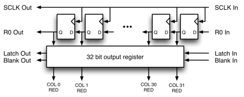
In order to understand how these signals drive individual LEDs on the matrix, one must understand the hardware that they control. The matrix's RGB LEDs are driven by 6 column drivers, each having 32 outputs. Each panel has 3 column drivers. Each column driver can drive 32 LED's in each panel, either red, green or blue (because each of the 3 column drivers controls one of these 3 colors). As a result, the 6 column drivers can drive up to 192 individual red, green and blue LED's (each RGB LED consists of 3 individual red, green and blue LED's) at a time.
CLK LAT OE...
Each column driver is composed of a serial data input, a blanking input, a shift register, and a parallel output register. Data bits are passed into the shift register on the rising edge of each clock cycle. The clock is controlled using the signal CLK. Because there are 32 RGB LED's per row, 32 clock cycles must occur, in order to drive all LED's in a row. After 32 bits of data are passed into the shift register, the LATCH signal (which is set low before shifting in data bits to the shift register) must be asserted, in order to transfer the data bits from the shift register to the parallel output register. Output enable (OE) is pulled low at this point, in order to enable the column driver. It is pulled high again, when transitioning to a new row.
We designed our driver to operate on 32 bit, bit strings (of type uint32_t), in order to utilize all 32 LEDs in each row of the matrix. Each 32 bit string, was stored in a 32 element array of type, uint32_t. We assigned the base memory address of the array to a pointer, and used integer offset values to pass the different bit strings, stored in the array, into the matrix driver function. This method allowed us to pass 32 unique bit strings into all 32 rows of the LED matrix. The integer offsets corresponded to row numbers. For example an offset of 4, would increment the pointer, pointing at the memory address of row 0, by 4 memory addresses. Dereferencing the pointer with this offset (4), would give access to data bits governing the output of row 4 of the LED matrix (the fifth row).
For each row, we used a for loop (which iterated from 0 to 31) in order to shift all 192 data bits into the shift registers. We latched the data bits into the parallel output register, after shifting was completed, which allowed us to illuminate different individual LED's in each row. This allowed us to use 32 bit, bit strings, to create data structures and graphics.
The column driver also allowed us to give the illusion of motion, by turning different LED's on and off in adjacent rows.
Integrating an acceleration sensor to move an avatar...
Another significant technical challenge that we faced, was integrating the LPC 1758's acceleration sensor with a virtual avatar (the player sprite). We used feedback from the acceleration sensor's Y-axis tilt output, to govern the player sprite's lateral movement. In this day, the play had one dimension of control over the sprite, by adjusting the Y-axis tilt of the LPC 1758.
While the task using acceleration sensor feedback to control movement was fairly trivial, it induced a bug in the game. The player sprite flickered one column to the left or one column to the right intermittently, when moving. When the LPC 1758 was completely still, flickering did not occur.
We tried sampling the acceleration sensor 10 times and averaging the integer result, before scaling it by our chosen step value (83), in order to apply the appropriate bit shift to the player sprite. This did not resolve the flickering.
We also tried processing the acceleration Y-axis feedback in a separate task from where we drew the sprite. We included a 1ms delay for each task, as we were concerned that there may have been overlap of calculating acceleration sensor feedback and applying the bit shift to the player sprite.
A few modifications to our move_player_sprite() function led to a significant improvement in performance. We increased the acceleration sensor step size (which is used to scale the Y-axis feedback integer value into a bit shift offset) and implemented our software interpretation of bandpass filter. We also stored the difference between the previous acceleration sensor Y-axis feedback value and the current value in a variable. We used the absolute value of this difference to determine if the acceleration sensor had registered significant enough movement to justify changing the current sprite position offset value. We also increased the move_player_sprite() function's block time to 100ms, which allowed it to more accurately track real-time movement (as human hands don't move fast enough to justify a 1ms delay). These modifications significantly reduced player sprite flickering.
Tracking a moving sprite and integrating shooting...
Tracking the player sprite was a fairly trivial task, due to our player sprite only moving in one dimension (left and right). Because the player sprite was holding a 1 pixel wide gun, we continuously scanned the row where the gun was located, in order to determine which column of the LED matrix would be set as the projectile path. We constantly scanned for a data bit set to 1, which when found, would let us know exactly where in the row that the gun was located.
A "shoot" signal was triggered by a push button sensor, which unblocked the "fire_a_shot()" function. This function passed the gun's column location to the "projectile_path()" function, allowing the projectile sprite to travel vertically, towards a moving enemy sprite (or nothing at all).
Enemy sprites and re-spawn time...
We created 5 unique enemy sprites, using combinations of adjacent bit strings. Each enemy sprite traversed the LED matrix laterally and was managed by its own task. We used a random number generator in addition with a fixed-time modulus, in order to implement random re-spawn times of sprites. The enemy sprite's position in the virtual LED matrix array was incremented by one column, after a set time delay. Each enemy sprite had a unique time delay, in order to allow some sprites to move faster than others and thus be harder to shoot. Faster sprites were worth more points (when shot), while slower sprites, while easier to hit, resulted in less points added to the player's total game score.
Hit detection and scorekeeping...
Hit detection proved less challenging that we initially thought that it would be. When a projectile was fired at an enemy sprite, the projectile's position was tracked as it traversed the LED matrix, vertically. When the projectile's position was within one pixel of the enemy sprite (and directly beneath it), a hit was registered. Upon a hit, the all data bits in the rows containing the vanquished enemy sprite were cleared to "0", This effectively removed the enemy sprite from the game, until a new identical enemy sprite re-spawned. We incorporated a random number driven delay, to control the re-spawn time of enemy sprites. This random re-spawn time was applied upon hits, as well as if an enemy sprite successfully traversed all 32 columns of the matrix (without being hit by a projectile).
Start Procedure...
In order to create a "Start" message for the game (essentially an introduction to the game), we created a task function called "Start_Game()". This task loaded data bits comprising a starting message, into the virtual LED matrix array. It also used the unique task handles of the in-game task functions, in order to suspend them, while it ran. After a fixed delay of 10 seconds, All data bits in the virtual LED matrix were set to 0; creating a blank screen. Start_Game() then used the task handles of each in-game task, to resume them. This commenced the actual Spartan Warrior game. We also sent a high (1) signal to the other LPC 1758 micro-controller in the system, which interfaced with the mp3 decoder. Upon receiving this signal, the other micro-controller worked with the mp3 decoder to play the soundtrack.
Game Over Procedure...
In order to implement the "Game Over" message, we began by setting a delay of 60 seconds. This allowed the task to block for one minute (or the length of the actual in-game time). We adjusted the input integer parameter of the delay_ms() function, in order to ensure that 60 seconds of actual game time was allowed, before this task was called. We chose this value for the game time, for demo purposes only. We could have adjusted it to any value we wished. Once the delay time expired, all in-game tasks were suspended and all data bits in the virtual LED matrix array, were set to 0. The message "Game Over", was loaded into the array and displayed on the screen, as well as the player's score total (on the lower panel).
Soundtrack Integration...
<Bug/issue name>
SAMIR/ANDREW
Using the acceleration sensor to control player sprite movement resulted in the sprite flickering...
The player sprite flickered one column to the left or one column to the right intermittently, when moving. When the LPC 1758 was completely still, flickering did not occur.
We tried sampling the acceleration sensor 10 times and averaging the integer result, before scaling it by our chosen step value (83), in order to apply the appropriate bit shift to the player sprite. This did not resolve the flickering.
We also tried processing the acceleration Y-axis feedback in a separate task from where we drew the sprite. We included a 1ms delay for each task, as we were concerned that there may have been overlap of calculating acceleration sensor feedback and applying the bit shift to the player sprite. (12/7/18)
A few modifications to our move_player_sprite() function led to a significant improvement in performance. We increased the acceleration sensor step size (which is used to scale the Y-axis feedback integer value into a bit shift offset) and implemented our software interpretation of bandpass filter. We also stored the difference between the previous acceleration sensor Y-axis feedback value and the current value in a variable. We used the absolute value of this difference to determine if the acceleration sensor had registered significant enough movement to justify changing the current sprite position offset value. We also increased the move_player_sprite() function's block time to 100ms, which allowed it to more accurately track real-time movement (as human hands don't move fast enough to justify a 1ms delay). These modifications significantly reduced player sprite flickering. (12/10/18)
Writing to registers on the MP3 decoder...
When attempting to read the contents of reset values on the VS1053b registers, we were always receiving high impedance. This is the default value for the MISO line in SPI protocol. We changed the master clock speed to 24Mhz and finally we could read the contents of the reset values. Another important modification in our code was to reset the MP3 decoder through the reset pin before writing to the registers. Its important to initialize CS and XDCS pins high because they are active-low configured.
Conclusion
TEAM
Conclude your project here. You can recap your testing and problems. You should address the "so what" part here to indicate what you ultimately learnt from this project. How has this project increased your knowledge?
Project Video
Upload a video of your project and post the link here.
Project Source Code
References
Acknowledgement
Any acknowledgement that you may wish to provide can be included here.
References Used
- https://bikerglen.com/projects/lighting/led-panel-1up/
- https://www.sparkfun.com/sparkx/blog/2650
- https://learn.adafruit.com/32x16-32x32-rgb-led-matrix/
- https://learn.adafruit.com/adafruit-vs1053-mp3-aac-ogg-midi-wav-play-and-record-codec-tutorial/assembly
Appendix
You can list the references you used.
