F16: Titans
Contents
- 1 Titans
- 2 Abstract
- 3 Objectives & Introduction
- 4 Track Progress in KanBan
- 5 Team Members & Responsibilities
- 6 Project Schedule
- 7 Parts List & Cost
- 8 DBC File Implementation
- 9 Sensor Controller
- 10 Motor & I/O Controller
- 11 Geographical Controller
- 12 Communication Bridge Controller
- 13 Master Controller
- 14 Conclusion
- 15 References
Titans
Titans - Autonomous Navigating Car
Abstract
This section should be a couple lines to describe what your project does.
Objectives & Introduction
Show list of your objectives. This section includes the high level details of your project. You can write about the various sensors or peripherals you used to get your project completed.
Track Progress in KanBan
Team Members & Responsibilities
- Master Controller
- Haroldo Filho
- Urvashi Agrawal
- Motor Controller & I/O Module
- Sant Prakash Soy
- Saketh Sai Narayana
- Kayalvizhi Rajagopal (LCD)
- GPS/Compass Module
- Yang Thao (GPS)
- Daamanmeet Paul (Compass)
- Sensors
- Kayalvizhi Rajagopal
- Communication Bridge/Android App
- Parth Pachchigar
- Purvil Kamdar
Project Schedule
Legend: Motor & I/O Controller , Master Controller , Communication Bridge Controller, Geographical Controller, Sensor Controller , Team Goal
| Week# | Start Date | End Date | Task | Status |
|---|---|---|---|---|
| 1 | 09/13/2016 | 09/20/2016 |
|
Completed |
| 2 | 09/21/2016 | 09/27/2016 |
|
Completed |
| 3 | 09/28/2016 | 10/04/2016 |
|
Completed |
| 4 | 10/05/2016 | 10/11/2016 |
|
Completed |
| 5 | 10/12/2016 | 10/17/2016 |
|
Completed |
| 6 | 10/18/2016 | 10/24/2016 |
|
Completed |
| 7 | 10/25/2016 | 10/31/2016 |
|
Completed |
| 8 | 11/1/2016 | 11/7/2016 |
|
Completed |
| 9 | 11/8/2016 | 11/14/2016 |
|
Completed |
| 10 | 11/15/2016 | 11/21/2016 |
|
In Progress |
| 11 | 11/22/2016 | 11/28/2016 |
|
Not Started |
| 12 | 11/22/2016 | 11/28/2016 |
|
Not Started |
| 13 | 11/29/2016 | Presentation date |
|
Not Started |
Parts List & Cost
| Item# | Part Desciption | Vendor | Qty | Cost |
|---|---|---|---|---|
| 1 | RC Car - Traxxas 1/10 Slash 2WD | Amazon | 1 | $189.95 |
| 2 | Traxxas 2872X 5000mAh 11.1V 3S 25C LiPo Battery | Amazon | 1 | $56.99 |
| 3 | Traxxas 7600mAh 7.4V 2-Cell 25C LiPo Battery | Amazon | 1 | $70.99 |
| 4 | Traxxas 2970 EZ-Peak Plus 4-Amp NiMH/LiPo Fast Charger | Amazon | 1 | $35.99 |
| 5 | Bluetooth 4.0 BLE Bee Module (Dual Mode) | Robotshop | 1 | $19.50 |
| 6 | 4D systems 32u LCD | 4D systems | 1 | $41.55 |
| 7 | LV Maxsonar EZ0 Ultrasonic sensors | Robotshop | 5 | $124.75 |
| 8 | Devantech SF05 Ultrasonic sensor | Provided by Preet | 1 | Free |
| 9 | Venus GPS with SMA connector | Amazon | 1 | $49.95 |
| 10 | SMA Male Plug GPS Active Antenna | Amazon | 1 | $9.45 |
| 11 | Wire wrapping board | Radio shack | 1 | $20.0 |
| 12 | CAN tranceivers | Digikey | 10 | $10.0 |
| 13 | SJOne Boards | Provided by Preet | 5 | $400.0 |
DBC File Implementation
- The following is the DBC file of the project.
VERSION ""
NS_ : BA_ BA_DEF_ BA_DEF_DEF_ BA_DEF_DEF_REL_ BA_DEF_REL_ BA_DEF_SGTYPE_ BA_REL_ BA_SGTYPE_ BO_TX_BU_ BU_BO_REL_ BU_EV_REL_ BU_SG_REL_ CAT_ CAT_DEF_ CM_ ENVVAR_DATA_ EV_DATA_ FILTER NS_DESC_ SGTYPE_ SGTYPE_VAL_ SG_MUL_VAL_ SIGTYPE_VALTYPE_ SIG_GROUP_ SIG_TYPE_REF_ SIG_VALTYPE_ VAL_ VAL_TABLE_
BS_:
BU_: DBG MASTER GPS MOTOR SENSOR APP
BO_ 1 APP_START_STOP: 8 APP
SG_ APP_START_STOP_cmd : 0|1@1+ (1,0) [0|0] "COMMAND" MASTER
SG_ APP_ROUTE_latitude : 1|28@1+ (0.000001,-90.000000) [-90|90] "" MASTER
SG_ APP_ROUTE_longitude : 29|29@1+ (0.000001,-180.000000) [-180|180] "" MASTER
SG_ APP_FINAL_COORDINATE : 58|1@1+ (1,0) [0|0] "" MASTER
SG_ APP_COORDINATE_READY : 59|1@1+ (1,0) [0|0] "" MASTER
BO_ 80 APP_ROUTE_DATA: 8 APP
SG_ APP_READOUT_latitude : 0|28@1+ (0.000001,-90.000000) [-90|90] "" MASTER
SG_ APP_READOUT_longitude : 28|29@1+ (0.000001,-180.000000) [-180|180] "" MASTER
BO_ 16 SENSOR_DATA: 3 SENSOR
SG_ SENSOR_left_sensor : 0|8@1+ (1,0) [0|0] "Inches" MASTER,APP,MOTOR
SG_ SENSOR_middle_sensor : 8|8@1+ (1,0) [0|0] "Inches" MASTER,APP,MOTOR
SG_ SENSOR_right_sensor : 16|8@1+ (1,0) [0|0] "Inches" MASTER,APP,MOTOR
BO_ 32 MASTER_HB: 8 MASTER
SG_ MASTER_SPEED_cmd : 0|3@1+ (1,0) [0|0] "" SENSOR,MOTOR,GPS,APP
SG_ MASTER_STEER_cmd : 3|3@1+ (1,0) [0|0] "" SENSOR,MOTOR,GPS,APP
SG_ MASTER_LAT_cmd : 6|28@1+ (0.000001,-90.000000) [-90|90] "" SENSOR,MOTOR,GPS,APP
SG_ MASTER_LONG_cmd : 34|29@1+ (0.000001,-180.000000) [-180|180] "" SENSOR,MOTOR,GPS,APP
SG_ MASTER_START_COORD : 63|1@1+ (1,0) [0|0] "" SENSOR,MOTOR,GPS,APP
BO_ 65 GPS_Data: 8 GPS
SG_ GPS_READOUT_valid_bit : 0|1@1+ (1,0) [0|1] "" MASTER,MOTOR,APP
SG_ GPS_READOUT_read_counter : 1|6@1+ (1,0) [0|60] "" MASTER,MOTOR,APP
SG_ GPS_READOUT_latitude : 7|28@1+ (0.000001,-90.000000) [-90|90] "" MASTER,MOTOR,APP
SG_ GPS_READOUT_longitude : 35|29@1+ (0.000001,-180.000000) [-180|180] "" MASTER,MOTOR,APP
BO_ 66 COMPASS_Data: 2 GPS
SG_ COMPASS_Heading : 0|9@1+ (1,0) [0|0] "DEGREE" MASTER,APP,MOTOR
BO_ 67 GEO_Header: 3 GPS
SG_ GPS_ANGLE_degree : 0|12@1+ (0.1,-180) [-180.0|180.0] "Degree" MASTER,MOTOR,APP
SG_ GPS_DISTANCE_meter : 12|12@1+ (0.1,0) [0.0|400.0] "Meters" MASTER,MOTOR,APP
BO_ 48 MOTOR_STATUS: 2 MOTOR
SG_ MOTOR_STATUS_speed_mph : 0|16@1+ (0.001,0) [0|0] "mph" MASTER,APP
CM_ BU_ MASTER "The master controller driving the car"; CM_ BU_ MOTOR "The motor controller of the car"; CM_ BU_ SENSOR "The sensor controller of the car"; CM_ BU_ APP "The communication bridge controller of car"; CM_ BU_ GPS "GPS and compass controller of the car"; CM_ BO_ 100 "Sync message used to synchronize the controllers";
BA_DEF_ "BusType" STRING ; BA_DEF_ BO_ "GenMsgCycleTime" INT 0 0; BA_DEF_ SG_ "FieldType" STRING ;
BA_DEF_DEF_ "BusType" "CAN"; BA_DEF_DEF_ "FieldType" ""; BA_DEF_DEF_ "GenMsgCycleTime" 0;
BA_ "GenMsgCycleTime" BO_ 32 100; BA_ "GenMsgCycleTime" BO_ 16 100; BA_ "GenMsgCycleTime" BO_ 48 100; BA_ "GenMsgCycleTime" BO_ 65 100; BA_ "GenMsgCycleTime" BO_ 66 100;
Sensor Controller
Design & Implementation
The main purpose of the sensor controller is Obstacle avoidance and one of the straight forward way to achieve the goal is to use an Ultrasonic sensor.
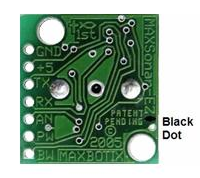
Sensor controller being the “eye” of the project, lot of thoughts were put into deciding the right sensor to serve the purpose of obstacle avoidance. Considering the factors of reliability and cost, Maxbotix EZ0 ultrasonic sensor is chosen to be left and right sensors. EZ ‘0’ model is selected because it has the widest beam coverage of all the Maxbotix EZ series sensor models. Devantech SF05 ultrasonic sensor is selected for the middle sensor. A different model is used for middle sensor because of its different frequency, which avoids interference between sensors.
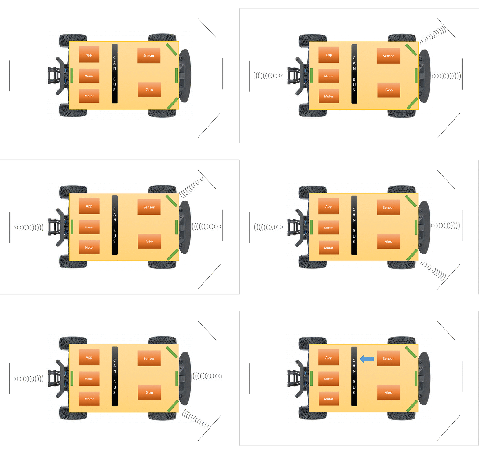
The sensors are mounted and tested at different angles so that the front three sensors cover a wide area, without leaving any dead or uncovered region.
Hardware Design
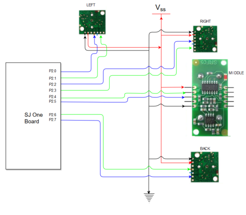
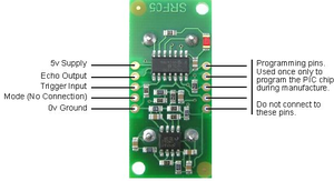
The sensors are interfaced using Port 2 GPIO pins of the microcontroller. The sensors require 5V power supply, which was provided from the main board’s supply. The trigger input to the sensors and the PWM output are interfaced to the GPIO pins as shown below in table. The pins for each sensor are chosen in such a way that it would not tangle each other while physically connecting them on the main board. CAN 1 of the SJOne board is connected to the CAN bus of the car which is also shown in the table below.
| Pin Name | Function |
|---|---|
| P2_0 | Trigger for left sensor |
| P2_1 | Echo for left sensor |
| P2_2 | Trigger for middle sensor |
| P2_3 | Echo for middle sensor |
| P2_4 | Trigger for right sensor |
| P2_5 | Echo for right sensor |
| P0_1 | CAN Tx |
| P0_2 | CAN Rx |
3D Printing Design
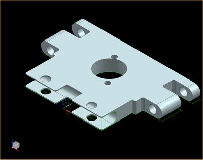
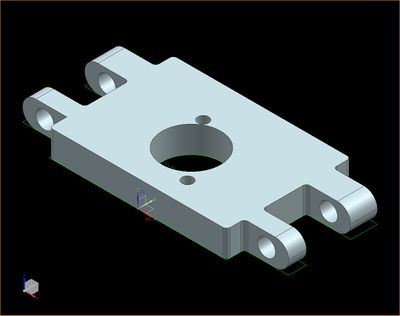
Sensors are required to be placed at a minimum height of 18 cm from the ground and at a tilt of 5 degrees to avoid ground reflections. A proper mount is required to place them at adjustable angles and heights. Hence the mounts are 3D printed using the below 3D deigns. The heights are adjustable by adding mode standoffs and the angle is adjustable by using the bottom screws.
Hardware Interface
The sensors are interfaced using GPIO pins. CAN 1 of the sensor controller is interfaced to the CAN bus of the car. Below diagram shows the hardware interface between the micro controller, sensors and the CAN bus.
Software Design
Software is designed such that the no two sensors of same type/model close by will be triggered simultaneously, so as to avoid interference with each other. Since the left and right sensor are of the same model, they are triggered sequentially, every 50 ms. The Maxbotix sensors cannot be triggered faster than 49 ms because it takes the sensors a maximum of 49 ms to pull down the PWN pin low when there is no obstacle for 6 meters or 254 inches. If triggered sooner, the reflected waves from the sensor will interfere with the next sensor, giving unpredictable values. The middle sensor and the back sensor are triggered every 50 ms. Hence we get all 4 sensor readings in 100 ms. The triggering of sensors is handled in 1 ms task, but with the check to trigger only every 50 ms. Refer the below datasheets for timing information for triggering and detailed working of both sensor models.
Maxbotix EZ0: http://www.maxbotix.com/documents/LV-MaxSonar-EZ_Datasheet.pdf
Devantech SF05:https://www.robot-electronics.co.uk/htm/srf05tech.htm
Implementation
Algorithm
1. Initialize the trigger pins as output and PWM pins as input
2. Configure the PWM pins for falling edge interrupt
3. Trigger left and middle and back sensor and start the timer for all three
4. Wait for echo from all of them
5. When echo is received, calculate the distance in inches using the below formula
Distance = (stop time – start time)/147
6. Trigger right and middle sensor and start the timer for both & repeat from step 4
7. Broadcast the sensor values on CAN bus
Below is the sample interrupt callback function(ISR) to calculate the distance of obstacle.
The flowcharts shown describes in detail on how each sensor is triggered and broadcasted over CAN every 100 ms.
Testing & Technical Challenges
Motor & I/O Controller
Motor and I/O controller is one of the five controller in the autonomous car. It is responsible for car's steering, movement, input commands and to display critical information regarding the car. The controller is connected to different hardware modules that take care of the mentioned features. These modules comprise of servo motor which is used for steering, electronic speed controller for controlling the DC motor which in turn controls the movements of the car and a touch-screen LCD display for data input and to display critical information. These modules are explained in further detail in hardware interface section of the Motor & I/O Controller below.
Design & Implementation
The design section can go over your hardware and software design. Organize this section using sub-sections that go over your design and implementation.
Hardware Design
The motor and I/O controller hardware design consists of SJOne microcontroller board connected to servo motor, electronics speed control, LCD module and LED lights. Servo motor and electronics speed control are connected to the microcontroller using PWM signal. The touch screen LCD is connected to the microcontroller board using UART interface. The LED lights are connected to the board using GPIO interface. The electronic speed controller is powered using the 6v power supply from the car battery pack. The servo motor for steering control is power on using 5V from the power bank. The touch screen LCD module is also powered on using the 5V using the power bank.
Hardware Interface
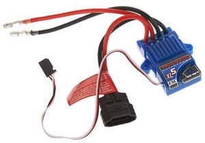
Electronic Speed Controller (ESC)
The Electronic Speed Controller is a component used for feeding PWM signal to a DC motor to control the speed at which it rotates. In addition to the speed it also controls the direction in which the motor rotates. These features help the car move forward and reverse and do these in different speeds. From the diagram below you can see the ESC has three color coded wires that are used for PWM signal(WHITE Color), VCC(RED Color) and GND(BLACK Color). These three color coded wires connect to the SJOne micro-controller board and power bank used in the car. There are also two wires coded red and black that have wire adapter at the end connect to the battery pack. The other two red and black wire connect directly to the DC Motor. The ESC also has a EZ Set button to switch between different speed modes, calibrate the speed and steering, and most important of all switch on the ESC itself. Please refer to the documentation provided by TRAXXAS for using the ESC.
| S.No | Wires on (ESC) | Description | Wire Color Code |
|---|---|---|---|
| 1. | (+)ve | Connects to DC Motor (+)ve | RED |
| 2. | (-)ve | Connects to DC Motor (-)ve | BLACK |
| 3. | (+)ve | Connects to (+)ve of Battery | RED |
| 4. | (-)ve | Connects to (-)ve of Battery | BLACK |
| 5. | P2.1 | PWM Signal From SJOne | WHITE |
| 6. | NC | NC | RED |
| 7. | (-)ve | Negetive terminal | BLACK |
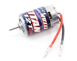
DC Motor
The DC motor is the primary component that controls the rotation of the car wheel. Based on the direction of the current flow to the motor it rotates the wheel in forward or backward direction. Also, based on the amount of current flow to the motor, it controls the speed at which the wheels rotate. In the figure below you can see the DC motor has to two wire, red and black for (+)ve and (-)ve connection respectively. For forward movement of the wheels the current flows from (+)ve to (-)ve. For reverse movement the current flows from (-)ve and (+)ve. For controlling the speed of the wheel the motor is fed with different amount of current from the ESC, which is controlled based on the duty cycle fed to ESC.
| S.No | Wires on (ESC) | Description | Wire Color Code |
|---|---|---|---|
| 1. | (+)ve | Positive Terminal | RED |
| 2. | (-)ve | Negetive terminal | BLACK |
Servo Motor
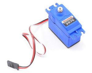
The servo motor is the component responsible for the steering of the car. The servo motor is controller directly from the SJOne micro-controller board. It has three color coded wire white, red and black which are used for PWM signal, 5 Volts and GND respectively. Based on the duty cycle of the signal sent to the servo, it rotates in left/right direction.
| S.No | Pin No. (SJOne Board) | Function | Wire Color Code |
|---|---|---|---|
| 1. | P2.4 | PWM Signal | WHITE |
| 2. | VCC | 5 Volts | RED |
| 3. | GND | 0 volts | BLACK |
Speed Sensor
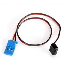
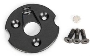
The speed sensor is one of the hardware component used in the autonomous car for sensing the speed of the car and feeding the information to SJOne microcontroller. The sensor is installed in the gear compartment of the Traxxas car along with the magnet trigger. When the magnet attached to the spur gear rotates along with the gear it passes the hall-effect RPM sensor after every revolution. As soon as the magnet comes in front of the sensor the sensor sends a pulse on the signal line which is color coded as white. The other color coded wires red and black are used for VCC and GND to power the sensor. The sensor is powered using the 5 volts power supply from the power bank.
| S.No | Pin No. (SJOne Board) | Function | Wire Color Code |
|---|---|---|---|
| 1. | P2.4 | PWM Signal | WHITE |
| 2. | VCC | 5 Volts | RED |
| 3. | GND | 0 volts | BLACK |
IO module
IO module consists of touch LCD for displaying critical information, head lights, brake lights and running lights. The LCD is interfaced to UART3 of the micro controller. The lights are interfaced via the GPIO pins.
The below figure shows how data from different nodes get to the LCD via CAN bus. It also shows how configurations done via LCD touch screen get to all other nodes via CAN bus.
Software Design
Motor Controller
Software design for the motor controller consist of different software modules that control speed, steering, inputs and outputs interface using touch screen LCD, and sensing the speed of the car. Controlling speed, steering and sensing speed is done using 10Hz periodic loop. On the other hand the code for LCD input and output run as a task that get scheduled in between the 10Hz periodic scheduler.
The second phase of the motor controlling is maintaining a constant speed i,e., to find out the speed at which it is running and control the car based on the speed at which it is traveling. This comes in handy when the car has a destination that goes uphill. This operation can be called as speed controlling. This operation is done with the help of a speed sensor that can be fixed either on to the wheel or on to the transmission box of the car.
DC Motor and Servo Motor
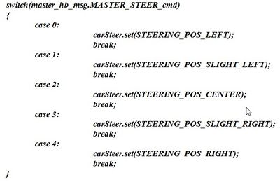
Software design for the speed control and steering control is done using 10Hz periodic loop. The periodic loop consists of two switch cases, one switch case for speed control and another one for steering control. For speed control, switch cases are for stop, 'slow' speed, 'medium' speed, 'fast' speed, and reverse. For steering control, the switch cases are for the positions of the wheel that are 'hard' left, 'slight' left, center, 'slight' right and 'hard' right.
IO module
Since motor's functional information is critical, the LCD uses UART as a communication medium to transmit messages. The LCD and lights working in the software is
designed as low priority tasks running at 500 ms. Even though UART takes a long time to process, it will not clog the periodic tasks.
The LCD is interfaced early in the project since it aids in debugging while the car is on the move. Critical information such as sensor readings, motor speed, compass direction, GPS coordinates, the degree to turn and distance to the destination are displayed on the LCD. The below screens show the information displayed on the LCD.
There is also a Settings menu through which the motor speed and sensor thresholds can be configured without having to re-build and re-flash the software.
Implementation
This section includes implementation, but again, not the details, just the high level. For example, you can list the steps it takes to communicate over a sensor, or the steps needed to write a page of memory onto SPI Flash. You can include sub-sections for each of your component implementation.
IO module algorithm
The critical data is received from different nodes via CAN and packed into packets and sent to the LCD via UART. The LCD used requires a specific format of data from the micro controller for it to display the data.Refer the below datasheet for information on the packet format for 4D systems uLCD-32PTU.
Datasheet: http://www.4dsystems.com.au/productpages/uLCD-32PTU/downloads/uLCD-32PTU_datasheet_R_2_0.pdf
User manual: http://www.4dsystems.com.au/productpages/PICASO/downloads/PICASO_serialcmdmanual_R_1_20.pdf
The below flowchart explains how the tasks work in order to transmit and receive data from the LCD.
Testing & Technical Challenges
Describe the challenges of your project. What advise would you give yourself or someone else if your project can be started from scratch again? Make a smooth transition to testing section and described what it took to test your project.
Geographical Controller
Design & Implementation
Geo Node's sole purpose is to provide the heading error angle and distance to checkpoint or destination for the Master Node. To be able to do this, the Geo Node requires gathering of current geo data and computing them to get what Master Node needs. The two required geo data are current gps coordinates and compass heading angle. Once these are gathered, Geo Node has to calculate the bearing angle which is the angle between two locations in respect to north. Using both bearing and compass heading angle, the heading error angle can be calculated. To get the distance, it requires two gps coordinates and a little bit of math.
Hardware Design
Discuss your hardware design here. Show detailed schematics, and the interface here.
- Below figure represents the block diagram of Geo Controller. Geo-controller uses GPS and IMU module for its working. Uart3 and Uart2 are used for interfacing IMU and GPS with SJ One board.
Hardware Interface
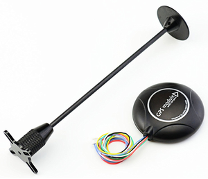
GPS Module: Readytosky Ublox NEO-M8N GPS Module
This GPS module uses UART serial communication interface. The refresh rate ranges from 1Hz up to 18Hz with a default baud rate of 9600bps. To achieve the desired refresh rate of 10Hz for our design, the baud rate had to be increased to 115200bps to accommodate for the demanded bandwidth from 10Hz refresh rate.
Specifications & Documentation: www.u-blox.com
GPS Connector Definition:
- GND,
- TX,data output
- RX,data intput
- VCC,2.7V-3.6V
Why choose u-blox GPS module?
There are several reasons to select this GPS module oppose to other types such as Sparkfun's popular Venus GPS. First, is the price. The u-blox GPS module can be purchased off amazon for about $35 with integrated antenna compared to the Venus for $50 with an additional ~$10-15 for the required external antenna. This brings up the next point and that has to do with the external antenna. Since the antenna's coaxial cable can range between 10 to 15 feet, it becomes a hassle trying to tuck it away on once GPS module is mounted on the RC car. Second point is the accuracy. The u-blox's data sheet claims have an accuracy of about 2 meters (Amazon.com seller claims 0.6 to 0.9 meter) compared to 2.5 meters on the Venus. Although these different GPS modules uses their own software to configure its settings, they all are identically configurable. This means it is a no-brainer to go for the u-blox GPS module.
Setting up u-blox GPS module:
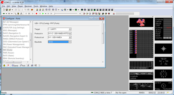
To be able to use u-blox center software to configure the GPS module, either u-blox's developer kit can be purchased or a cheaper alternative choice would be to purchase a FTDI USB to Serial adapter module for about $5 from any convenient online retailer. The u-blox software can be downloaded free from u-blox's website. Once connection is establish between the GPS module and computer, the software provides great number of configurations to change and also a wide GPS map tools to play with. Despite all the fun features the software provides, there are a few important settings that needed to be changed to fit our design.
On default, the refresh rate is set at 1000ms, or 1Hz. This had to be changed to 100ms to be able to get a refresh rate of 10Hz. Next, for the best accuracy possible from this GPS, Navigation Mode needs to be changed to "Pedestrian". This settings ensure best accuracy below speed of 30 meters/second which our RC car is well under. Lastly, since we are only interested in GPRMC messages from our GPS module, u-blox software provided option to turn off all messages except for GPRMC. This helps tremendously when trying to capture reliable messages.
The Readytosky GPS module has a soldered-on little super capacitor that charges up once power is provided and then acts as a battery once power is removed. Although this super capacitor helps by providing power to the memory to keep GSP configuration settings saved as well as provide a warm or hot start (faster to acquire accurate GPS data), it was only able to power for a few hours after power is removed. Although the datasheet says the memory is flash, it kept resetting back to default once battery power is gone. This meant configuration settings had to be redone often. To remedy this problem, the super capacitor had to be removed and in its place, a 3.3V coin battery soldered on.
Interfacing with SJ-One Board:
Interfacing this GPS module to the SJ-One board was straight forward. Since the communication type is UART, TX from GPS is tied to RXD2 pin on SJ-One and RX from GPS is tied to TXD2 pin utilizing UART2 port. Since the refresh rate was configured to 10hz, the default 9600 baud rate was not sufficient enough. Baud rate on both GPS module and SJ-One board both had to be changed to 115200 baud rate. Although baud could have lower and worked just fine, 115200 posed no issue so it was ideally better to get the message sooner and have a longer time in between the next message to avoid cascading messages in the UART read buffer.
**See Hardware Design for wire diagram.**
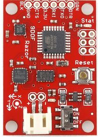
Razor IMU - 9 Degrees of Freedom
The 9DOF Razor IMU incorporates three sensors - an ITG-3200 (MEMS triple-axis gyro), ADXL345 (triple-axis accelerometer), and HMC5883L (triple-axis magnetometer) - to output nine degrees of inertial measurement. The outputs of all sensors are processed by an on-board ATmega328 and output over a serial interface.
Software Design
Show your software design. For example, if you are designing an MP3 Player, show the tasks that you are using, and what they are doing at a high level. Do not show the details of the code. For example, do not show exact code, but you may show psuedocode and fragments of code. Keep in mind that you are showing DESIGN of your software, not the inner workings of it.
Implementation
This section includes implementation, but again, not the details, just the high level. For example, you can list the steps it takes to communicate over a sensor, or the steps needed to write a page of memory onto SPI Flash. You can include sub-sections for each of your component implementation.
Testing & Technical Challenges
GPS Module
Communication Bridge Controller
Design & Implementation
The design section can go over your hardware and software design. Organize this section using sub-sections that go over your design and implementation.
Hardware Design
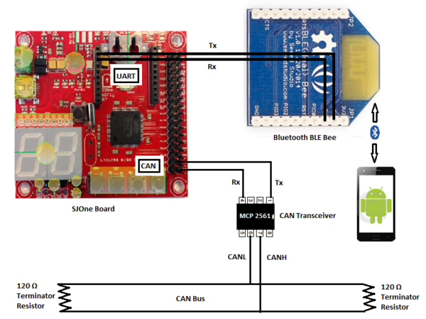
Here is the hardware block diagram of Communication Bridge Controller.
Here is the hardware block diagram of Communication Bridge Controller. Here is the hardware block diagram of Communication Bridge Controller. Here is the hardware block diagram of Communication Bridge Controller.
Hardware Interface
In this section, you can describe how your hardware communicates, such as which BUSes used. You can discuss your driver implementation here, such that the Software Design section is isolated to talk about high level workings rather than inner working of your project.
Software Design
Show your software design. For example, if you are designing an MP3 Player, show the tasks that you are using, and what they are doing at a high level. Do not show the details of the code. For example, do not show exact code, but you may show psuedocode and fragments of code. Keep in mind that you are showing DESIGN of your software, not the inner workings of it.
Implementation
This section includes implementation, but again, not the details, just the high level. For example, you can list the steps it takes to communicate over a sensor, or the steps needed to write a page of memory onto SPI Flash. You can include sub-sections for each of your component implementation.
Testing & Technical Challenges
Describe the challenges of your project. What advise would you give yourself or someone else if your project can be started from scratch again? Make a smooth transition to testing section and described what it took to test your project.
Master Controller
Design & Implementation
The design section can go over your hardware and software design. Organize this section using sub-sections that go over your design and implementation.
Hardware Design
Discuss your hardware design here. Show detailed schematics, and the interface here.
Hardware Interface
In this section, you can describe how your hardware communicates, such as which BUSes used. You can discuss your driver implementation here, such that the Software Design section is isolated to talk about high level workings rather than inner working of your project.
Software Design
Show your software design. For example, if you are designing an MP3 Player, show the tasks that you are using, and what they are doing at a high level. Do not show the details of the code. For example, do not show exact code, but you may show psuedocode and fragments of code. Keep in mind that you are showing DESIGN of your software, not the inner workings of it.
Implementation
This section includes implementation, but again, not the details, just the high level. For example, you can list the steps it takes to communicate over a sensor, or the steps needed to write a page of memory onto SPI Flash. You can include sub-sections for each of your component implementation.
Testing & Technical Challenges
Describe the challenges of your project. What advise would you give yourself or someone else if your project can be started from scratch again? Make a smooth transition to testing section and described what it took to test your project.
My Issue #1
Discuss the issue and resolution.
Conclusion
Conclude your project here. You can recap your testing and problems. You should address the "so what" part here to indicate what you ultimately learnt from this project. How has this project increased your knowledge?
Project Video
Upload a video of your project and post the link here.
Project Source Code
References
Acknowledgement
Any acknowledgement that you may wish to provide can be included here.
References Used
List any references used in project.
Appendix
You can list the references you used.
