S23: CAN CLAN
Contents
CAN CLAN
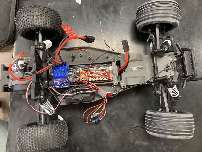
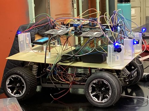
Picture of the RC Car
Abstract
Our goal for this project is to use knowledge we gathered from lectures to design, implement, and test a self-driving RC car using a Controller Area Network (CAN) bus for controller communication. The project involves FreeRTOS and utilizes periodic tasks (running at 1Hz, 10Hz, and 100Hz) to gather, process, and display data from various embedded modules.
Introduction
The project was divided into 5 modules:
- Sensor Information
- Motor Operation
- Geological Information
- Driver & LCD Manager
- Bridge & Android Application
Team Members & Responsibilities
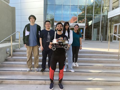
<Team Picture>
Gitlab Project Link - https://gitlab.com/rashmi_sv/the_CAN_clan.git
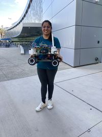
Rashmi Suhas Vaidya
- Driver Controller
- Motor Controller
- Geo Controller
- GPS Interfacing
- Integration Testing
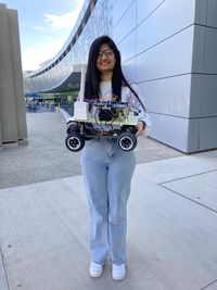
Zeel Jatinkumar Lia
- Sensor and Bridge Controller
- Ultrasonic sensors
- LCD interfacing
- Integration Testing
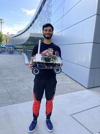
Priyam Hajisheth
- Hardware mounting
- Mobile App
- Integration Testing
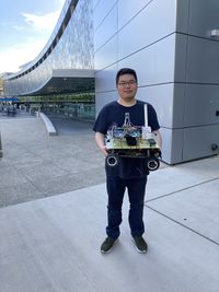
Xinyu He
- Hardware solution
- Wiki Page Update
- Integration Testing
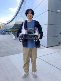
Hongjin Cheng
- Protoboard soldering and Hardware assembling
- Compass, RPM Sensor, DC and servo motor interfacing
- Integration Testing
Schedule
| Week# | Start Date | End Date | Task | Status |
|---|---|---|---|---|
| 1 | 03/01/2023 | 03/07/2023 |
|
|
| 2 | 03/08/2023 | 03/14/2023 |
|
|
| 3 | 03/15/2023 | 03/21/2023 |
|
|
| 4 | 03/22/2023 | 03/28/2023 |
|
|
| 5 | 03/29/2023 | 04/04/2023 |
|
|
| 6 | 04/05/2023 | 04/11/2023 |
|
|
| 7 | 04/12/2022 | 04/18/2022 |
|
|
| 8 | 04/19/2023 | 04/25/2023 |
|
|
| 9 | 04/26/2023 | 05/02/2023 |
|
|
| 10 | 05/03/2023 | 05/09/2023 |
|
|
| 11 | 05/10/2023 | 05/16/2023 |
|
|
| 11 | 05/23/2023 | 05/23/2023 |
|
|
Parts List & Cost
| Item# | Part Desciption | Vendor | Qty | Cost |
|---|---|---|---|---|
| 1 | RC Car | Traxxas [1] | 1 | $251.51 |
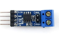
| 2 | CAN Transceivers | Amazon [2] | 4 | $43.72 |
| 3 | SJ-2 Board | 4 | $200.00 | |
| 4 | LV-MaxSonar-EZ1 Ultrasonic Range Finder | Amazon [3] | 4 | $131.20 |
| 5 | GPS | Amazon [4] | 1 | $10.99 |
| 6 | RPM Sensor | Amazon [5] | 1 | $16.76 |
| 7 | Buletooth | Amazon[6] | 1 | $15.99 |
| 8 | LCD Display | Amazon [7] | 1 | $10.99 |
| 9 | Battery/Charger | 1 | $62.95 | |
| 10 | Cable | Amazon [8] | 1 | $7.99 |
| 11 | LSM303AGR Compass | Adafruit [9] | 1 | $19.57 |
| 12 | Magnet holder | 1 | $8.09 | |
| 13 | 2*20 header | 1 | $7.59 | |
| 14 | RPM holder | 1 | $7.73 | |
| 15 | long stand off | 1 | $2.21 | |
| 16 | Mount board | 1 | None | |
| 17 | Protoboard | 1 | None | |
| 18 | Small stand off | None | ||
| 19 | Pin header | None | ||
| 20 | Switch for DC motor | 1 | None | |
| 21 | wire connectors | 1 | None |
Printed Circuit Board
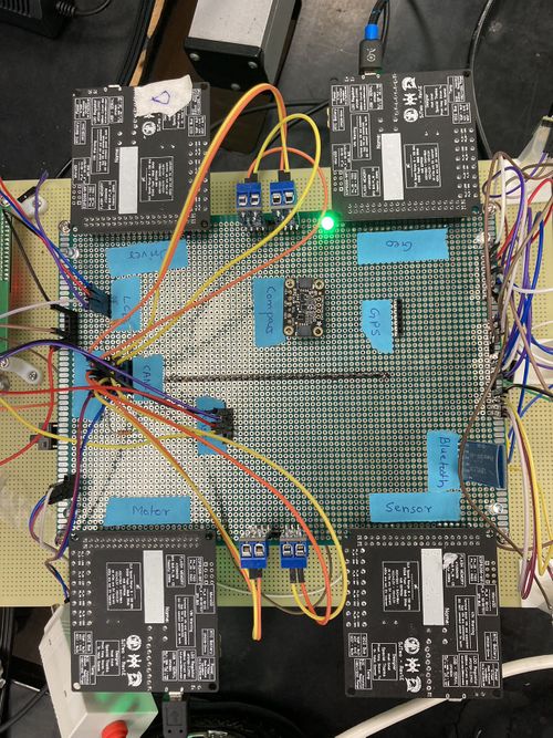
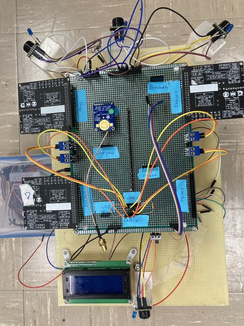
The Following table indicate the pin connection of all Hardware .
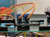
This is the pictures show protoboard and the mount board.
CAN Communication
<Talk about your message IDs or communication strategy, such as periodic transmission, MIA management etc.> We are using 100HZ for CAN bus communication, 50HZ for sensors, 10HZ for calculation, 1HZ for printing. The following table shows the Message ID.
| Node | Message ID | |
|---|---|---|
| 1 | ULTRASONIC_TO_DRIVER | 100 |
| 2 | GPS_DESTINATION | 300 |
| 3 | DRIVE_STATUS_CMD | 50 |
| 4 | SELF_TEST_CMD | 600 |
| 5 | DRIVER_TO_MOTOR | 200 |
| 6 | DRIVER_SELF_TEST_RESULT | 610 |
| 7 | GEO_STATUS | 400 |
| 8 | GEO_SELF_TEST_RESULT | 620 |
| 9 | GEO_CURRENT_COORDS | 650 |
| 10 | MOTOR_TO_APP_DBG | 500 |
Hardware Design
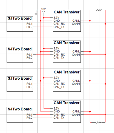
<Show your CAN bus hardware design>
- The following is the CAN Transceiver Design logicwork.
DBC File
Gitlab link to our DBC file : https://gitlab.com/rashmi_sv/the_CAN_clan/-/blob/dev/dbc_file/dbc/project.dbc
<You can optionally use an inline image>
VERSION ""

NS_ :
        BA_
        BA_DEF_
        BA_DEF_DEF_
        BA_DEF_DEF_REL_
        BA_DEF_REL_
        BA_DEF_SGTYPE_
        BA_REL_
        BA_SGTYPE_
        BO_TX_BU_
        BU_BO_REL_
        BU_EV_REL_
        BU_SG_REL_
        CAT_
        CAT_DEF_
        CM_
        ENVVAR_DATA_
        EV_DATA_
        FILTER
        NS_DESC_
        SGTYPE_
        SGTYPE_VAL_
        SG_MUL_VAL_
        SIGTYPE_VALTYPE_
        SIG_GROUP_
        SIG_TYPE_REF_
        SIG_VALTYPE_
        VAL_
        VAL_TABLE_

BS_:

BU_: DBG DRIVER GEO MOTOR SENSOR_BRIDGE


BO_ 100 ULTRASONIC_TO_DRIVER: 5 SENSOR_BRIDGE
 SG_ ULTRASONIC_TO_DRIVER_left : 0|10@1+ (1,0) [0|511] "cm" DRIVER
 SG_ ULTRASONIC_TO_DRIVER_right : 10|10@1+ (1,0) [0|511] "cm" DRIVER
 SG_ ULTRASONIC_TO_DRIVER_front : 20|10@1+ (1,0) [0|511] "cm" DRIVER
 SG_ ULTRASONIC_TO_DRIVER_back : 30|10@1+ (1,0) [0|511] "cm" DRIVER

BO_ 300 GPS_DESTINATION: 8 SENSOR_BRIDGE
 SG_ GPS_DEST_LATITUDE_SCALED_100000 : 0|32@1- (1,0) [0|0] "Degrees" GEO
 SG_ GPS_DEST_LONGITUDE_SCALED_100000 : 32|32@1- (1,0) [0|0] "Degrees" GEO

BO_ 50 DRIVE_STATUS_CMD: 1 SENSOR_BRIDGE
 SG_ DRIVE_STATUS_CMD_start : 0|1@1+ (1,0) [0|0] "" MOTOR

BO_ 600 SELF_TEST_CMD: 1 SENSOR_BRIDGE
 SG_ SELF_TEST_CMD_start : 0|1@1+ (1,0) [0|0] "" MOTOR, GEO, DRIVER


BO_ 200 DRIVER_TO_MOTOR: 2 DRIVER
 SG_ DRIVER_TO_MOTOR_steer : 0|8@1- (1,0) [0|0] "degrees" MOTOR, SENSOR_BRIDGE
 SG_ DRIVER_TO_MOTOR_speed : 8|8@1- (1,0) [0|50] "mph" MOTOR, SENSOR_BRIDGE

BO_ 610 DRIVER_SELF_TEST_RESULT: 1 DRIVER
 SG_ DRIVER_SELF_TEST_RESULT_status : 0|8@1+ (1,0) [0|0] "" SENSOR_BRIDGE


BO_ 400 GEO_STATUS: 8 GEO
  SG_ GEO_STATUS_COMPASS_HEADING : 0|12@1+ (1,0) [0|359] "Degrees" DRIVER, SENSOR_BRIDGE
  SG_ GEO_STATUS_COMPASS_BEARING : 12|12@1+ (1,0) [0|359] "Degrees" DRIVER, SENSOR_BRIDGE
  SG_ GEO_STATUS_DISTANCE_TO_DESTINATION : 24|16@1+ (0.1,0) [0|0] "Meters" DRIVER, SENSOR_BRIDGE
  SG_ GEO_STATUS_SATELLITE_LOCKED : 40|1@1+ (1,0) [0|0] "" DRIVER, SENSOR_BRIDGE

BO_ 620 GEO_SELF_TEST_RESULT: 1 GEO
 SG_ GEO_SELF_TEST_RESULT_status : 0|8@1+ (1,0) [0|0] "" SENSOR_BRIDGE

BO_ 650 GEO_CURRENT_COORDS: 8 SENSOR_BRIDGE
 SG_ CURR_LATITUDE_SCALED_100000 : 0|32@1- (1,0) [0|0] "Degrees" SENSOR_BRIDGE
 SG_ CURR_LONGITUDE_SCALED_100000 : 32|32@1- (1,0) [0|0] "Degrees" SENSOR_BRIDGE


BO_ 500 MOTOR_TO_APP_DBG: 2 MOTOR
 SG_ MOTOR_TO_APP_DBG_current_steer : 0|8@1- (1,0) [0|0] "degrees" SENSOR_BRIDGE
 SG_ MOTOR_TO_APP_DBG_current_speed : 8|8@1- (1,0) [0|50] "mph" SENSOR_BRIDGE

BO_ 620 MOTOR_SELF_TEST_RESULT: 1 MOTOR
 SG_ MOTOR_SELF_TEST_RESULT_status : 0|8@1+ (1,0) [0|0] "" SENSOR_BRIDGE


CM_ BU_ DRIVER "The LED display and driver controller driving the car";
CM_ BU_ MOTOR "The RPM sensor, DC and servo motor controller of the car";
CM_ BU_ SENSOR_BRIDGE "The Bluetooth and the sonar sensor controller of the car";
CM_ BU_ GEO "The GPS and compass sensor controller of the car";

BA_DEF_ "BusType" STRING ;
BA_DEF_ BO_ "GenMsgCycleTime" INT 0 0;
BA_DEF_ SG_ "FieldType" STRING ;

BA_DEF_DEF_ "BusType" "CAN";
BA_DEF_DEF_ "FieldType" "";
BA_DEF_DEF_ "GenMsgCycleTime" 0;

BA_ "GenMsgCycleTime" BO_ 100 1000;
BA_ "GenMsgCycleTime" BO_ 200 50;
Sensor ECU
<Picture and link to Gitlab> Sensor Node GitLab
Hardware Design
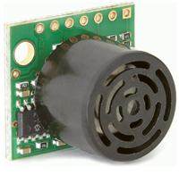
LV-MaxSonar-EZ1 Ultrasonic Range Finder
- MaxSonar-EZ1 detects objects from 0" to 254".
- 2.5-5.5V operation range. Low 2mA supply current.
- 42kHz Ultrasonic sensor with 20Hz reading rate.
- Incredibly Small Package Sonar Range Finder.
- Serial Output, PWM output, Analog Output.
Sensor Design
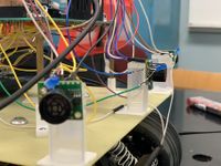
- We used 4 sensors-LV-MaxSonar-EZ1 Ultrasonic Range Finder. These ultrasonic sensors are used by the RC car for the purpose of obstacle avoidance. Three sensors were placed on the front side of the RC car and one on the back. They use I2C communication to send distance data to the SJ2 microcontroller. On the SJ2 microcontroller, P0.10 was used for SDA, and P0.11 was used for SCL. It takes in +5V supply voltage. A LED is soldering on sensors to indicate if the sensor is working well.
Software Design
<List the code modules that are being called periodically.>
- Sensors are divided into two groups:
- 1. Front-rear group
- 2. Left-right group
Each group use 50HZ. The following code shows how it being called periodically.
void periodic_callbacks__100Hz(uint32_t callback_count) {
  CAN_RX_MSGS_FOR_BRIDGE();
  Sensor_Controller__100hz_handler(callback_count);
  can_ultrasonic_sensor_transmit_messages();
}
The following is the code for sensor controller.
#include "LV_sensor_controller.h"
#include "LV_sensor_pin_init.h"

static dbc_ULTRASONIC_TO_DRIVER_s ultra_sonic_data;

static gpio_s FRONT_OBSTACLE_LED;
static gpio_s LEFT_OBSTACLE_LED;
static gpio_s RIGHT_OBSTACLE_LED;
static gpio_s BACK_OBSTACLE_LED;

void Sensor_Controller_init(void) {
  FRONT_OBSTACLE_LED = gpio__construct_as_output(GPIO__PORT_2, 2);
  LEFT_OBSTACLE_LED = gpio__construct_as_output(GPIO__PORT_2, 0);
  RIGHT_OBSTACLE_LED = gpio__construct_as_output(GPIO__PORT_2, 1);
  BACK_OBSTACLE_LED = gpio__construct_as_output(GPIO__PORT_2, 4);
  adc_init_for_LV_sensors();
  trigger_pins_for_LV_sensors();
}

void Sensor_Controller__print_sensor_values() {
  printf("L:%d F:%d R:%d B:%d\n", ultra_sonic_data.ULTRASONIC_TO_DRIVER_left,
         ultra_sonic_data.ULTRASONIC_TO_DRIVER_front, ultra_sonic_data.ULTRASONIC_TO_DRIVER_right,
         ultra_sonic_data.ULTRASONIC_TO_DRIVER_back);
}

static void update_obstacle_LED(int sensor_value, gpio_s obstacle_led) {
  if (sensor_value > 100) { // no obstacle detected. Turn OFF LED
    gpio__reset(obstacle_led);
  } else {
    gpio__set(obstacle_led); // obstacle detected. Turn ON LED
  }
}

void Sensor_Controller__100hz_handler(uint32_t callback_count) {
  if (callback_count % 2 == 0) {
    collect_left_LV_sensor_values_buffer();
    ultra_sonic_data.ULTRASONIC_TO_DRIVER_left = sort_sensor_buffer_data_and_get_median(LEFT_ULTRA_SONIC);
    update_obstacle_LED(ultra_sonic_data.ULTRASONIC_TO_DRIVER_left, LEFT_OBSTACLE_LED);

    collect_right_LV_sensor_values_buffer();
    ultra_sonic_data.ULTRASONIC_TO_DRIVER_right = sort_sensor_buffer_data_and_get_median(RIGHT_ULTRA_SONIC);
    update_obstacle_LED(ultra_sonic_data.ULTRASONIC_TO_DRIVER_right, RIGHT_OBSTACLE_LED);
  }

  else {

    collect_back_LV_sensor_values_buffer();
    ultra_sonic_data.ULTRASONIC_TO_DRIVER_back = sort_sensor_buffer_data_and_get_median(BACK_ULTRA_SONIC);
    update_obstacle_LED(ultra_sonic_data.ULTRASONIC_TO_DRIVER_back, BACK_OBSTACLE_LED);

    collect_front_LV_sensor_values_buffer();
    ultra_sonic_data.ULTRASONIC_TO_DRIVER_front = sort_sensor_buffer_data_and_get_median(FRONT_ULTRA_SONIC);
    update_obstacle_LED(ultra_sonic_data.ULTRASONIC_TO_DRIVER_front, FRONT_OBSTACLE_LED);
  }
}
dbc_ULTRASONIC_TO_DRIVER_s get_ultra_sonic_data(void) { return ultra_sonic_data; }
Technical Challenges
< List of problems and their detailed resolutions>
- Issue: Sensors test well independently, but not sensitive when mount on RC car .
- Reason: Sensor do not have enough power supply.
- Solution: 1.check connecting and solder in protoboard.
- 2.Re-design the power supply plan.
- Issue: While using two brand sensors, Front sensor works well, but left/right sensor working randomly. For sensors couldn’t work well at the same time.
- Reason: We config the sensor in two groups, and it causes the sensors to crosstalk.
- Solution: 1. Only use one brand.
- 2.Turning on only two sensors at a time.(left + right then front +rear).
- Issue: Rear Sensor doesn't work well with bad mounting.
- Reason: the sensors are mounted heading to LCD.
- Solution: we use higher stand off of read sensor.
Motor ECU
<Picture and link to Gitlab> Motor Controller Link
Hardware Design
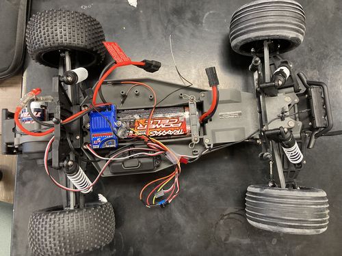
On protoboard, a single SJ2-C board labeled motor was designed to control Traxxas car, in witch included DC motor for back-forward control, a servo motor for steering control, and a RPM sensor for speed control.
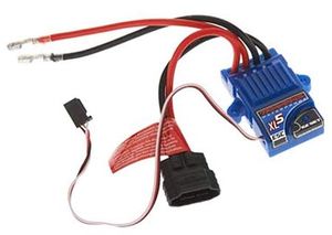
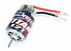
Following are the key hardware component from the car.
Servo Motor
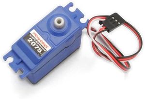
We are using Traxxas 2075 for this project which came with the car and it is responsible for steering the car. It takes the 6V power directly from ESC. The servo motor is controlled directly from the SJ2 micro-controller board. The PWM signal is supplied at a frequency of 100 Hz. Based on the duty cycle of the signal sent to the servo, the direction of servo motor can be changed.
RPM Sensor
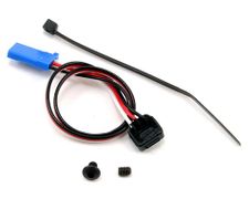
The RPM sensor is used as an input to maintain a constant speed of the vehicle. The sensor we are using is Traxxas RPM sensor which using hall effect to detect the movement of the DC motor.
Mounting
Software Design
<List the code modules that are being called periodically.>
motor.h
#pragma once
#include <stdint.h>
void motor__init(void);
// Apply brake by setting the ESC throttle to neutral
void brake();

// Set the throttle to go forward
void go_forward(float dc_speed);

// Set the throttle to go in reverse
void go_reveser();

// Set the servo motor to go straight
void go_straight();

// Set the servo motor to turn left
void go_left(float servo_speed);

// Set the servo motor to turn right
void go_right(float servo_speed);

}
Technical Challenges
< List of problems and their detailed resolutions>
- Issue: RC-Car sometimes goes forward while the code commands it to backward, whereas sometimes goes backward when the code commands it to go forward.
- Reason: Do not initialize the RC car.
- Solution: Keep Neutral With remote more than 3 seconds. Otherwise, it may fail to receive the correct signals.
- Issue: Giving the command with sequence Forward-Neutral-backward. The car acts as Forward-stop-Forward.
- Reason: ignored the RC-Car protection mechanism.
- Solution: The command should be Forward-Neutral-Backward-Backward
Geographical Controller
<Picture and link to Gitlab>
Hardware Design
- GPS
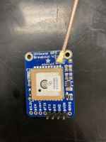
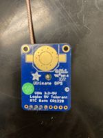
- An Adafruit Ultimate GPS breakout module using the MTK3339 chipset is interfaced over UART to the Geographical controller to provide latitude and longitude updates.
- Compass
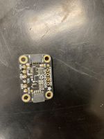
- Triple-axis accelerometer/magnetometer compass module. Inside are two sensors, one is a classic 3-axis accelerometer, which can tell you which direction is down towards the Earth (by measuring gravity). The other is a magnetometer that can sense where the strongest magnetic force is coming from, generally used to detect magnetic north.
Software Design
<List the code modules that are being called periodically.>
Technical Challenges
< List of problems and their detailed resolutions>
Communication Bridge Controller & LCD
<Picture and link to Gitlab>
Hardware Design
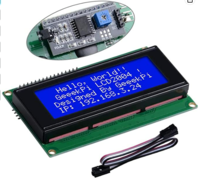
- LCD
- An Adafruit Ultimate GPS breakout module using the MTK3339 chipset is interfaced over UART to the Geographical controller to provide latitude and longitude updates.
Software Design
<List the code modules that are being called periodically.>
LCD_int.h
#pragma once

#include <stdint.h>

void init__LCD(void);

void reset__LCD(void);

void send_LCD_char(uint8_t character);

void send_LCD_string(char *input_string);

void send_LCD_command(uint8_t command);

void set_LCD_to_4_bit_mode(void);


}
LCD_process.h
#pragma once

#include "project.h"

void update_sensor_for_LCD(dbc_ULTRASONIC_TO_DRIVER_s *sensor_data);
void update_compass_for_LCD(dbc_GEO_STATUS_s *compass_data);
void update_motor_for_LCD(dbc_DRIVER_TO_MOTOR_s *motor_data_s);

void LCD_display_1Hz(void);
// void LCD_status__display_handle_1hz(void);

}
Technical Challenges
< List of problems and their detailed resolutions>
Master Module
<Picture and link to Gitlab>
Hardware Design
Software Design
<List the code modules that are being called periodically.>
Technical Challenges
< List of problems and their detailed resolutions>
Mobile Application
<Picture and link to Gitlab>
Hardware Design
Software Design
<List the code modules that are being called periodically.>
Technical Challenges
< List of problems and their detailed resolutions>
Conclusion
<Organized summary of the project>
<What did you learn?>
Project Video
Project Source Code
Advise for Future Students
<Bullet points and discussion>
Acknowledgement
=== References ===
