S22: Testla
Contents
Testla
Abstract
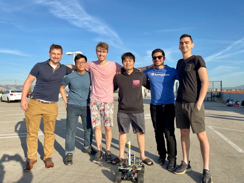
The Testla project is the culmination of our efforts to create an autonomously operated RC Car by pooling together our experience in software design, hardware design, power systems, and mobile application development. Project development started in February of 2022 and ended in May. (NOTE: One more sentence probably)
Introduction
The project was divided into 5 modules:
- Bridge and Sensor Information
- Motor Operation
- Geological Information
- Driver and LCD Manager
- Android Application
Team Members & Responsibilities
- Devin Alexander Gitlab
- Co-Leader
- Geographical Controller
- Master Controller
- Sinan Bayati Gitlab
- PCB Design
- Motor Controller
- Michael Hatzikokolakis Gitlab
- Co-Leader
- Motor Controller
- Testing
- Scott LoCascio Gitlab
- Geographical Controller
- Car Construction
- Testing
- Thinh Lu Gitlab
- Android Application
- Sensor and Bridge Controller
- Bang Nguyen Gitlab
- Sensor and Bridge Controller
- LCD Display
Schedule
| Week # | Start Date | End Date | Task | Status |
|---|---|---|---|---|
| 1 | 2/15/2022 | 2/21/2022 | Read previous projects, gather information and discuss among the group members. | Complete |
| 2 | 2/22/2022 | 2/28/2022 | Distribute modules to each team member. | Complete |
| 3 | 3/1/2022 | 3/7/2022 | Purchase the RC Car Purchase sensors |
Complete |
| 4 | 3/8/2022 | 3/14/2022 | Learning to use CAN BUSMASTER | Complete |
| 5 | 3/15/2022 | 3/21/2022 | DBC file discussed and implemented | Complete |
| 6 | 3/22/2022 | 3/28/2022 | Discuss modules needed for PCB, any feature requests | Complete |
| 7 | 3/29/2022 | 4/4/2022 | Finalize preparations and research | Complete |
| 8 | 4/5/2022 | 4/11/2022 | Interface with RC car and hack steering and motor Integrate the GEO sensor with the GEO controller Complete the Driver sensor using analog readings Write a basic implementation of the sensor controller Interface ESP8266 for bridge controller Begin testing with single vs dual power supplies |
Complete |
| 9 | 4/12/2022 | 4/18/2022 | Install wheel encoder, implement, implement PID into velocity processing, and establish collaboration between the Motor and Sensor Controllers Test alternate sonar sensor (I2C) Configure GPS to run at 10Hz, 115200 baud and only parse $GPGGA strings on startup Integrate compass Setup NodeJS server to communicate with the Bridge controller via TCP/IP Start Mobile Application development. Finalize power supply choice Finish PCB designs for each subsystem |
Complete |
| 10 | 4/19/2022 | 4/25/2022 | Finish 1st vehicle prototype - include PCBs if possible Complete basic mobile application Write various motor test routines to define in mobile application Verify timing and correctness of GEO controller messages. Produce debug messages for Geo controller Generate debug messages for all controllers. Finalize sensor choice and complete integration of all three sensors. |
Complete |
| 11 | 4/26/2022 | 5/2/2022 | Identify first PCB design inefficiencies/failures and submit the second and final draft for production Thoroughly test the motor's performance on sloped terrain and refine PID controller Test message timing and propagation with Bus Master Improve existing navigation algorithm with state estimation and localization Integration testing Driver controller with Mobile App |
Complete |
| 12 | 5/3/2022 | 5/9/2022 | Finished mobile application More testing, update schedule as needed |
Complete |
| 13 | 5/10/2022 | 5/16/2022 | Final prototype complete | Complete |
| 14 | 5/17/2022 | 5/25/2022 | Last tests | Incomplete |
Parts List & Cost
| Item# | Part Desciption | Vendor | Qty | Cost |
|---|---|---|---|---|
| 1 | Unassembled RC Car | Traxxas [1] | 1 | $279.99 |
| 2 | CAN Transceivers | Amazon [2] | 1 | $8.99 |
| 2 | CAN Transceivers | Amazon [3] | 1 | $8.99 |
| 2 | CAN Transceivers | Amazon [4] | 1 | $8.99 |
| 2 | CAN Transceivers | Amazon [5] | 1 | $8.99 |
| 2 | CAN Transceivers | Amazon [6] | 1 | $8.99 |
Printed Circuit Board
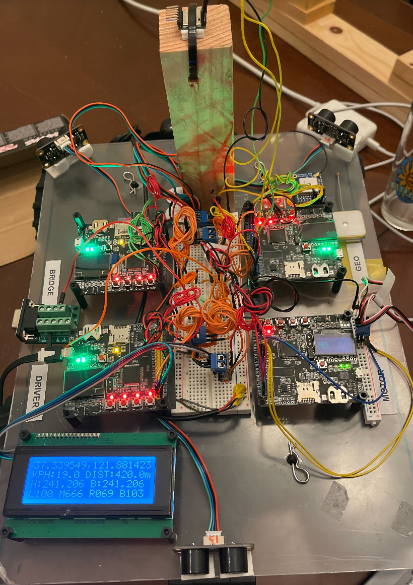
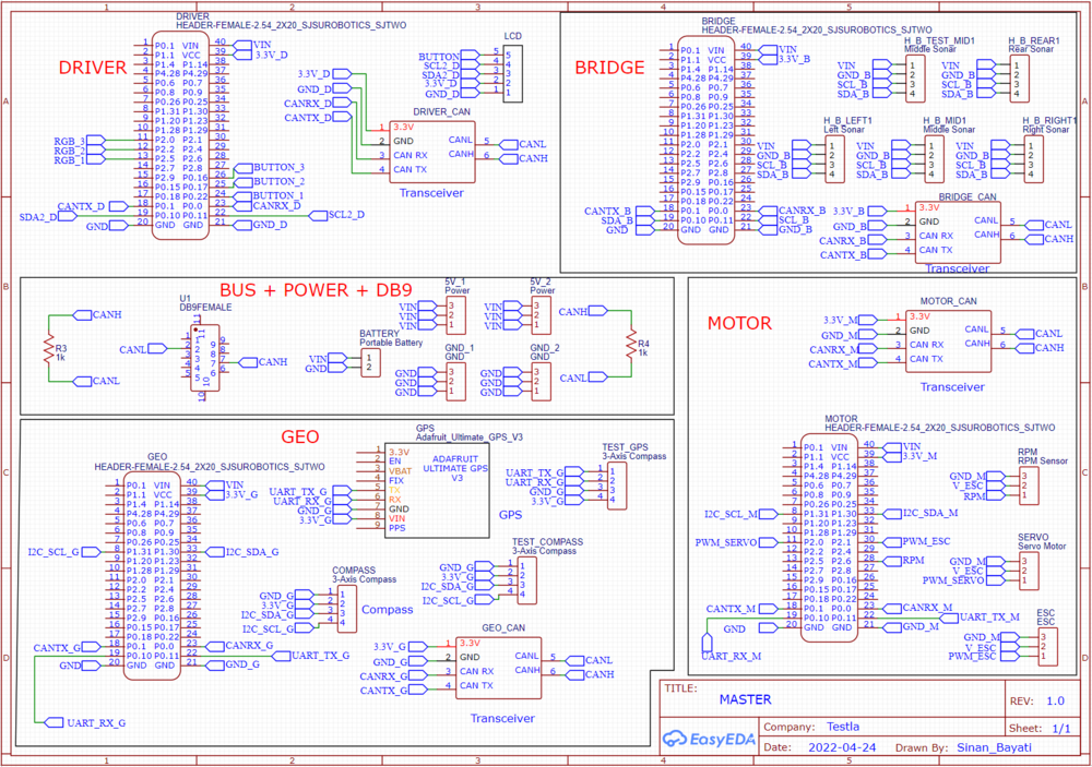
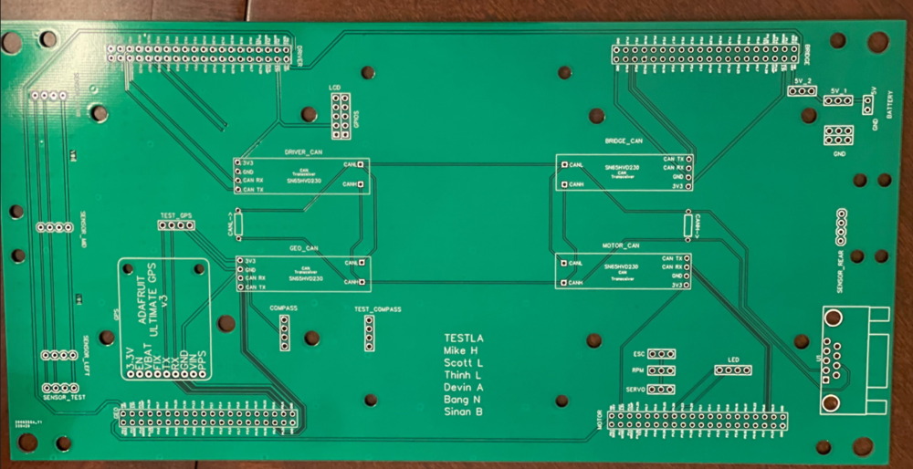
The preliminary design consisted of neatly routes wires on a breadboard connecting all the various components. It still looked confusing due to the sheer amount of connections that had to be made, this complexity was to be handled by a custom PCB designed in EasyEDA.
Challenges
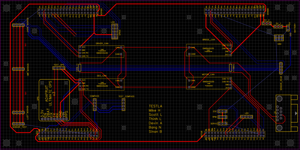
We found that some wires we used were faulty and did not conduct electricity, this led to alot of debug time which could have been avoided by using another wire. To avoid this type of scenario, you can do a continuity check with a multimeter to ensure wire integrity. We chose to design a PCB to have a clean on the car and have higher pin connection strength, since bread board connections are too loose.
The design has many holes for mounting and pinouts for various peripherals (GPS, LCD, Buttons, etc.)
Steps to design PCB: Following this general guideline will help you avoid any blockers.
- Finish preliminary breadboard wiring and track changes along the way
- Identify desired mounting topology and make measurements
- Use pcb software to make schematic diagram (not PCB wiring)
- Make holes in the pcb for desired mounting locations (The more the merrier)
- Start positioning the components, then begin making traces
CAN Communication
<Talk about your message IDs or communication strategy, such as periodic transmission, MIA management etc.>
Hardware Design
<Show your CAN bus hardware design>
DBC File
VERSION ""

NS_ :
	BA_
	BA_DEF_
	BA_DEF_DEF_
	BA_DEF_DEF_REL_
	BA_DEF_REL_
	BA_DEF_SGTYPE_
	BA_REL_
	BA_SGTYPE_
	BO_TX_BU_
	BU_BO_REL_
	BU_EV_REL_
	BU_SG_REL_
	CAT_
	CAT_DEF_
	CM_
	ENVVAR_DATA_
	EV_DATA_
	FILTER
	NS_DESC_
	SGTYPE_
	SGTYPE_VAL_
	SG_MUL_VAL_
	SIGTYPE_VALTYPE_
	SIG_GROUP_
	SIG_TYPE_REF_
	SIG_VALTYPE_
	VAL_
	VAL_TABLE_

BS_:

BU_: DRIVER MOTOR SENSOR GEO DEBUG


BO_ 100 DRIVER_HEARTBEAT: 3 DRIVER
 SG_ DRIVER_HEARTBEAT_cmd : 0|8@1+ (1,0) [0|0] "" DBG

BO_ 110 DRIVER_STEERING: 3 DRIVER
 SG_ DRIVER_STEERING_yaw : 0|12@1+ (0.001,-2) [-10|10] "radians" MOTOR
 SG_ DRIVER_STEERING_velocity : 12|12@1+ (0.01,-20) [-20|20] "kph" MOTOR

BO_ 120 MOTOR_HEARTBEAT: 5 MOTOR
 SG_ MOTOR_HEARTBEAT_speed_raw : 0|8@1+ (1,0) [0|0] "count" DEBUG
 SG_ MOTOR_HEARTBEAT_speed_rpm : 8|10@1+ (1,0) [0|0] "rpm" DEBUG
 SG_ MOTOR_HEARTBEAT_speed_kph : 18|10@1+ (0.1,-10) [-10|10] "kph" DEBUG
 SG_ MOTOR_HEARTBEAT_angle_duty : 28|10@1+ (0.001,-2) [-10|10] "duty" MOTOR


BO_ 125 MOTOR_DEBUG: 8 MOTOR
 SG_ MOTOR_DEBUG_speed_target : 0|26@1+ (0.1,-10) [-10|10] "kph" DEBUG
 SG_ MOTOR_DEBUG_speed_kph : 26|10@1+ (0.1,-10) [-10|10] "kph" DEBUG
 SG_ MOTOR_DEBUG_speed_duty : 36|10@1+ (0.1,0) [0|0] "duty" DEBUG
 SG_ MOTOR_DEBUG_integral_error : 46|10@1+ (0.1,-10) [-10|10] "error" DEBUG
 SG_ MOTOR_DEBUG_current_state : 56|3@1+ (1,0) [0|5] "state" DEBUG
 SG_ MOTOR_DEBUG_next_state : 59|3@1+ (1,0) [0|5] "state" DEBUG


BO_ 128 MOTOR_ESC_CALIBRATED: 1 MOTOR
 SG_ MOTOR_ESC_CALIBRATED_calibration_status : 0|4@1+ (1,0) [0|3] "esc_calibration_e" DRIVER
 SG_ MOTOR_ESC_CALIBRATED_start_calibration_ack_to_driver : 4|1@1+ (1,0) [0|1] "bool" DRIVER


BO_ 129 DRIVER_START_ESC_CALIBRATION: 1 DRIVER
 SG_ MOTOR_ESC_CALIBRATED_begin_esc_calibration : 0|1@1+ (1,0) [0|3] "bool" MOTOR

BO_ 130 MOTOR_ACK: 1 MOTOR
 SG_ MOTOR_ACK_cmd : 0|8@1+ (1,0) [0|0] "" DRIVER


BO_ 200 SENSOR_SONARS: 8 SENSOR
 SG_ SENSOR_SONARS_left : 0|10@1+ (1,0) [0|800] "inch" DRIVER
 SG_ SENSOR_SONARS_right : 10|10@1+ (1,0) [0|0] "inch" DRIVER
 SG_ SENSOR_SONARS_middle : 20|10@1+ (1,0) [0|0] "inch" DRIVER
 SG_ SENSOR_SONARS_back : 30|10@1+ (1,0) [0|0] "inch" DRIVER
 SG_ SENSOR_SONARS_frame_id : 42|16@1+ (1,0) [0|0] "" DRIVER

BO_ 210 SENSOR_DESTINATION_LOCATION: 8 SENSOR
 SG_ SENSOR_DESTINATION_latitude : 0|28@1+ (0.000001,-90.000000) [-90|90] "Degrees" GEO
 SG_ SENSOR_DESTINATION_longitude : 28|28@1+ (0.000001,-180.000000) [-180|180] "Degrees" GEO

BO_ 218 NAVIGATION_MESSAGE: 1 GEO
 SG_ NAVIGATION_STATUS_navigation_status : 0|8@1+ (1,0) [0|3] "navigation_status_e" DRIVER

BO_ 219 CHECKPOINT_MESSAGE: 8 GEO
 SG_ CHECKPOINT_MESSAGE_compass_heading : 0|12@1+ (1,0) [0|359] "Degrees" DRIVER
 SG_ CHECKPOINT_MESSAGE_destination_bearing : 12|12@1+ (1,0) [0|359] "Degrees" DRIVER
 SG_ CHECKPOINT_MESSAGE_destination_distance : 24|16@1+ (0.1,0) [0|0] "Meters" DRIVER
 SG_ CHECKPOINT_MESSAGE_curr_checkpoint_num : 40|8@1+ (1,0) [0|255] "Integer" DRIVER
 SG_ CHECKPOINT_MESSAGE_total_checkpoint_num : 48|8@1+ (1,0) [0|255] "Integer" DRIVER
 SG_ CHECKPOINT_MESSAGE_checkpoint_status : 56|8@1+ (1,0) [0|3] "checkpoint_status_e" DRIVER

BO_ 220 GEO_STATUS: 8 GEO
 SG_ GEO_STATUS_compass_heading : 0|12@1+ (1,0) [0|359] "Degrees" DRIVER
 SG_ GEO_STATUS_destination_bearing : 12|12@1+ (1,0) [0|359] "Degrees" DRIVER
 SG_ GEO_STATUS_destination_distance : 24|16@1+ (0.1,0) [0|0] "Meters" DRIVER

BO_ 520 DEBUG_GPS_CURRENT_LOCATION: 8 GEO
 SG_ DEBUG_GPS_CURRENT_LOCATION_latitude : 0|28@1+ (0.000001,-90.000000) [-90|90] "Degrees" DEBUG
 SG_ DEBUG_GPS_CURRENT_LOCATION_longitude : 28|28@1+ (0.000001,-180.000000) [-180|180] "Degrees" DEBUG
 SG_ DEBUG_GPS_CURRENT_LOCATION_fix : 56|2@1+ (1,0) [0|2] "" DEBUG

BO_ 521 DEBUG_GEO_GPS_UPDATE: 8 GEO
 SG_ DEBUG_GEO_GPS_UPDATE_count : 0|16@1+ (1,0) [0|0] "" DEBUG
 SG_ DEBUG_GEO_GPS_UPDATE_max_period : 16|16@1+ (1,0) [0|0] "milliseconds" DEBUG
 SG_ DEBUG_GEO_GPS_UPDATE_min_period : 32|16@1+ (1,0) [0|0] "milliseconds" DEBUG
 SG_ DEBUG_GEO_GPS_UPDATE_average_period : 48|16@1+ (1,0) [0|0] "milliseconds" DEBUG

BO_ 522 DEBUG_GEO_COMPASS_UPDATE: 8 GEO
 SG_ DEBUG_GEO_COMPASS_UPDATE_count : 0|16@1+ (1,0) [0|0] "" DEBUG
 SG_ DEBUG_GEO_COMPASS_UPDATE_max_period : 16|16@1+ (1,0) [0|0] "milliseconds" DEBUG
 SG_ DEBUG_GEO_COMPASS_UPDATE_min_period : 32|16@1+ (1,0) [0|0] "milliseconds" DEBUG
 SG_ DEBUG_GEO_COMPASS_UPDATE_average_period : 48|16@1+ (1,0) [0|0] "milliseconds" DEBUG

CM_ BU_ DRIVER "The driver controller driving the car";
CM_ BU_ MOTOR "The motor controller of the car";
CM_ BU_ SENSOR "The sensor controller of the car";
CM_ BU_ GEO "the geographical controller of the car";
CM_ BU_ DEBUG "the debug topic that all controllers can publish to";
CM_ BO_ 100 "Sync message used to synchronize the controllers";
CM_ SG_ 100 DRIVER_HEARTBEAT_cmd "Heartbeat command from the driver";

BA_DEF_ "BusType" STRING ;
BA_DEF_ BO_ "GenMsgCycleTime" INT 0 0;
BA_DEF_ SG_ "FieldType" STRING ;

BA_DEF_DEF_ "BusType" "CAN";
BA_DEF_DEF_ "FieldType" "";
BA_DEF_DEF_ "GenMsgCycleTime" 0;

BA_ "GenMsgCycleTime" BO_ 100 1000;
BA_ "GenMsgCycleTime" BO_ 200 50;
BA_ "FieldType" SG_ 100 DRIVER_HEARTBEAT_cmd "DRIVER_HEARTBEAT_cmd";

VAL_ 100 DRIVER_HEARTBEAT_cmd 2 "DRIVER_HEARTBEAT_cmd_REBOOT" 1 "DRIVER_HEARTBEAT_cmd_SYNC" 0 "DRIVER_HEARTBEAT_cmd_NOOP" ;
Sensor ECU
<Picture and link to Gitlab>
Hardware Design
Software Design
<List the code modules that are being called periodically.>
Technical Challenges
< List of problems and their detailed resolutions>
Motor ECU
<Picture> Motor Controller Link
Hardware Design
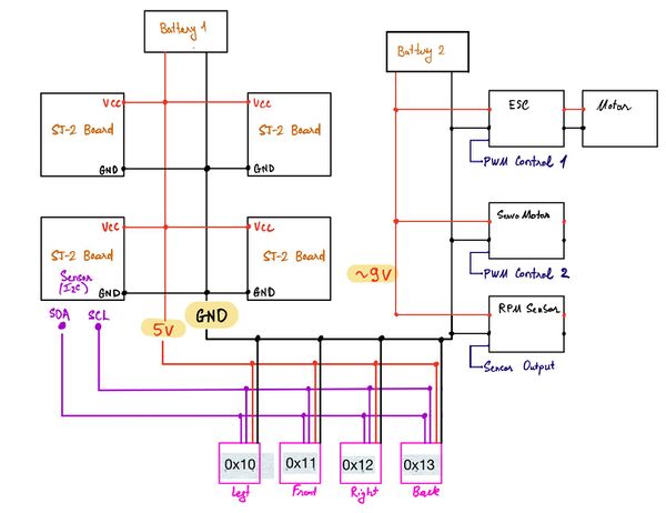
A single SJ2-C board was placed in charge of handling all interactions with the Traxxas parts. This included an ESC (Electronic Speed Control) connected to a brushed DC motor, a servo motor for steering control, and a wheel encoder installed adjacent to the gear shaft (CHECK).
Defining Signals
While Traxxas does provide support for hobby RC car enthusiasts, they do not provide clear documentation on signal inputs and outputs to all of their electrical components. To understand what signals would need to be generated by the SJ2-C (CHECK), the output of the receiver box (CHECK) was intercepted. Manipulating the Traxxas remote would generate PWM signals at the output of the receiver box. By reading these signals on an oscilloscope, it was determined that both the ESC and servo motor both operated on a range of duty cycles between 10 - 20%.
For the ESC: 10% DC = full reverse speed, 15% DC = idle/zero speed, 20% DC - full forward speed
For the servo motor: 10% DC = wheels fully turned to the left, 15% DC = wheels turned straight ahead, 20% DC = wheels turned fully to the right.
Setting up the PWM channels
The PWM channels on pins P2.0 (CHECK) and P2.1 were both enabled on single edge mode at a frequency of 100 Hz with a duty cycle of 15%. Initial tests were conducted by mapping the buttons of the SJ2 (CHECK) to modifying the duty cycles on both PWM channels. These tests were successful in changing the motor speed and wheel direction.
RPM Sensor
In order to give real-time feedback on the speed the car is traveling at, an RPM sensor was installed. For ease of compatibility, the Traxxas 6520 RPM Sensor (long variant) was purchased for this task. It was installed by following this youtube tutorial: https://www.youtube.com/watch?v=-26ZSgDqwQQ&t=241s. The other part used is the Traxxas 6538 Telemetry Trigger Magnet Holder for Spur Gear>. While this was expected to provide proper signal output with no extra components, initial testing of the sensor yielded an 0.4 Vpp signal comprised of an unstable, noisy signal. Doing further research led us to find that a 1k-ohm (CHECK) pull-up resistor connecting the data pin to a 3.3V rail was required to pull the signal high instead of letting it float. This corrected the output signal to give the expected result.
SJ2-C LED Breakdown
Normal Operation: LED 0: Toggle on CAN receive LED 1: Toggle on CAN transmit LED 2: Unused LED 3: Driver signal Missing-in-Action
ESC Calibration LEDs 0-2: Used to detail current step in calibration process LED 3: Unused
SJ2-C Switch Breakdown
Software Design
<List the code modules that are being called periodically.>
Technical Challenges
< List of problems and their detailed resolutions>
Geographical Controller
The geographical (geo) controller is used to provide the vehicle with a sense of location. To do this, the controller is interfaced to a compass which provides a heading, and a GPS module which provides a latitude, longitude, and GPS fix. GPS fix indicates that the GPS unit is connected to enough sattelites to provide accurate location data. The controller reads a destination off the CAN bus and calculates the distance from its current position. Additionally, it calculates a bearing, which is the degrees from north that the car must point to be facing the destination. If the car aligns its heading with the bearing and drives in a straight line for the number of meters described by the distance calculation, then the car will arrive at its destination.
However, the vehicle will not be driving in a straight line because of obstacle avoidance. To deal with this, the distance and bearing are updated regularly at a rate of 10Hz. When an obstacle forces the vehicle to deviate from the desired course, it will recalculate the bearing and distance from its new location. This distance and location is then broadcast on the CAN bus, and digested by the driver controller.
Hardware Design
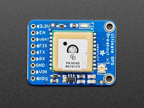
An Adafruit Ultimate GPS breakout module using the MTK3339 chipset is interfaced over UART to the Geographical controller to provide latitude and longitude updates.
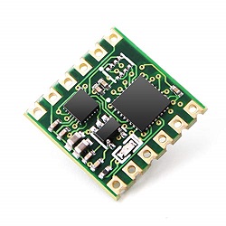
A Witmotion WT901 IMU is connected over I2C to provide access to the vehicles heading.
Software Design
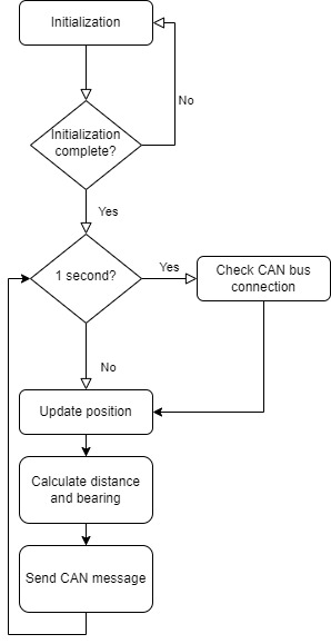
The general software flow is shown in the diagram below. This loop is run in a 10Hz periodic callback set up in FreeRTOS.
Initialization
On startup the GPS module is configured. The GPS module sends data at 9600 bps after powering on but must be set to 115200 bps to support 10Hz updates. The controller must send a command to increase the GPS module's baud rate then change the baud rate on its own UART interface. Initially, the GPS sends out several different NMEA strings on every update. The vehicle only needs latitude , longitude and GPS fix data so the GPS is configured to only send GPGGA strings. This prevents the geo controller from wasting time to intake data that it is uninterested in. Finally, the GPS module is configured to send updated data at a rate of 10Hz. After this process is complete, the controller enters its main loop.
Main Loop
The geo controller runs at a frequency of 10Hz. A FreeRTOS task uses vTaskDelayUntil() to define a finite period of 100 milliseconds between invocations of the periodic callback.
The GPS module is read by reading characters out of the UART into a line buffer. If a full line has been deposited into the buffer then the latitude, longitude and GPS Fix are updated. Additionally, a min and max time between GPS updates field is filled in as well as a count of updates. This debug information is published on the bus to analyze fidelity of the module.
Next, the compass is read over an I2C interface to acquire the heading. The WT901 is an IMU which actually has a good deal more information available besides heading. Currently we are only reading the compass heading but can expand expand in the future to read acceleration and orientation. This module does need to be calibrated one time to ensure it is correctly reporting the heading. The module has a UART interface which can be used to interface between a TTL to USB converter to a software suite. This software can also be used for debugging and calibration.
After reading the position the CAN interface checks if there are any changes to the destination being published by the bridge controller. After obtaining the most recent desired destination, the geographical module is invoked to calculate a distance and bearing. The section below goes into more detail on the geo calculation. After a distance and bearing are calculated, they are published onto the bis along with the current heading and dubug information.
Geo process
The desired and current position are used to calculate a distance and bearing using the haversine formula shown below.
Distance
Bearing
Moveable Type Scripts: Calculate distance, bearing and more between Latitude/Longitude points
Technical Challenges
There were several challenges in developing a reliable geographical controller.
Initially, connecting to the GPS was a challenge because the format of the ASCII lines were not well understood.
Expected string
$GPGGA,064951.000,2307.1256,N,12016.4438,E,1,8,0.95,39.9,M,17.8,M,,*65
Actual string
$GPGGA,,,,,,,5,,,,M,,*65
There were also issues with verifying that the command strings being sent were achieving their desired results
Both these problems were solved by attaching the tx line of the GPS to an oscilloscope and decoding the UART messages. This allowed us to fully characterize the output of the GPS and its response to command strings.
LCD, Sonar Sensor & Communication Bridge Controller
- Sensor Gitlab
Hardware Design
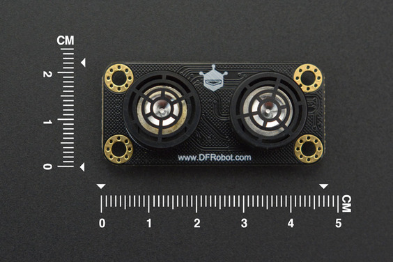
- Ultra-Sonic Sensor URM09 (I2C Protocol)
• Supply Voltage: 3.3~5.5V DC • Operating Current: 20mA • Operating Temperature Range: -10℃~+70℃ • Measurement Range: 2cm~500cm (can be set) • Resolution: 1cm • Accuracy: 1% • Frequency: 50Hz Max • Dimension: 47mm × 22 mm/1.85” × 0.87”
Software Design
- Low level - peripheral driver
- Peripheral Initialize function
- I2C Clock 100KHz
- I2C Pin:
- SCL: P0_10
- SDA: P0_11
- I2C single byte read function
- Input parameter
- Slave address (7-bit + R/W-bit)
- Register address (1 byte)
- Output parameter
- Register value (1 byte)
- Return true if success else return false
- Input parameter
- I2C single byte write function
- Input parameter
- Slave address (7-bit + R\W bit)
- Register address (1 byte)
- Written value (1 byte)
- Return true if success else return false
- Input parameter
- Peripheral Initialize function
- Mid-level -sensor
- Defined data struct
- Sonar_sensor__sample_sum_s
- Left
- Middle
- Right
- Back
- Sonar_sensor__sample_queue_s
- Left
- Middle
- Right
- Back
- Sonar_sensor__address_e
- Left (7-bits - 0x26)
- Middle (7-bits – 0x22)
- Right (7-bits – 0x24)
- Back (7-bits – 0x20)
- Sonar_sensor_measure_mode_e
- Automatic
- Passive
- Sonar_sensor__measure_range_e
- 150 cm
- 300 cm
- 500 cm
- Sonar_sensor__sample_sum_s
- Initialize sensor function
- Init I2C peripheral
- Init all the sensors with the following configurations:
- Passive measure mode
- 150 cm range
- Sensor collects sample function
- To avoid the sensor's crosstalk, we implement the following sequence
- Start the measurement left sensor
- Delay 25ms
- Collect data from the left sensor
- Start the measurement right sensor
- Delay 25ms
- Collect data from the right sensor
- Start the measurement back and middle
- Delay 25ms
- Collect data from the back and middle sensor
- To avoid the sensor's crosstalk, we implement the following sequence
Technical Challenges
< List of problems and their detailed resolutions>
Master Module
<Picture and link to Gitlab>
Hardware Design
Software Design
<List the code modules that are being called periodically.>
Technical Challenges
< List of problems and their detailed resolutions>
Mobile Application
<Picture and link to Gitlab>
Hardware Design
Software Design
<List the code modules that are being called periodically.>
Technical Challenges
< List of problems and their detailed resolutions>
Conclusion
<Organized summary of the project>
<What did you learn?>
Project Video
Project Source Code
Advise for Future Students
<Bullet points and discussion>
Acknowledgement
First and foremost we have to acknowledge all the teams who came before us. The largest source of information and inspiration came from them. There are an immense amount of well documented attempts at solving this problem. We truly in debt to the teams that came before us and hope we added something to the knowledge base here at Social Ledge.
Next, we have to acknowledge Professor Preetpal Kang. CmpE 243 is the product of a lot of hard work on his part. Preet makes himself available for all the students and shares his many years of experience and expertise. This is one of the most valuable part of the SJSU computer engineering masters program.
We also need to acknowledge the former students and others who work on the SJTwo repository and the Social Ledge website. This is another wealth of information and we could not have built this project without this resource.
Finally, We should (and do) acknowledge all of the teams in our class this semester. We were lucky to have an engaged group of teams working together and sharing knowledge and experiences.
