S22: Road Runner
Contents
Road Runner
Abstract
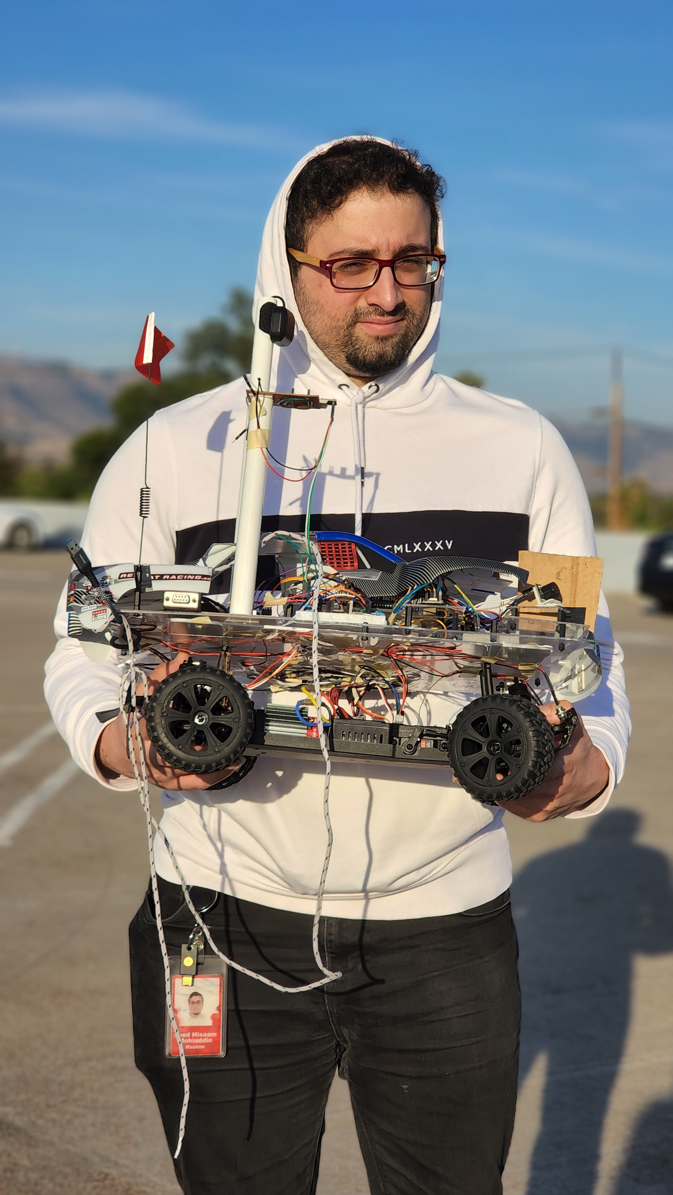
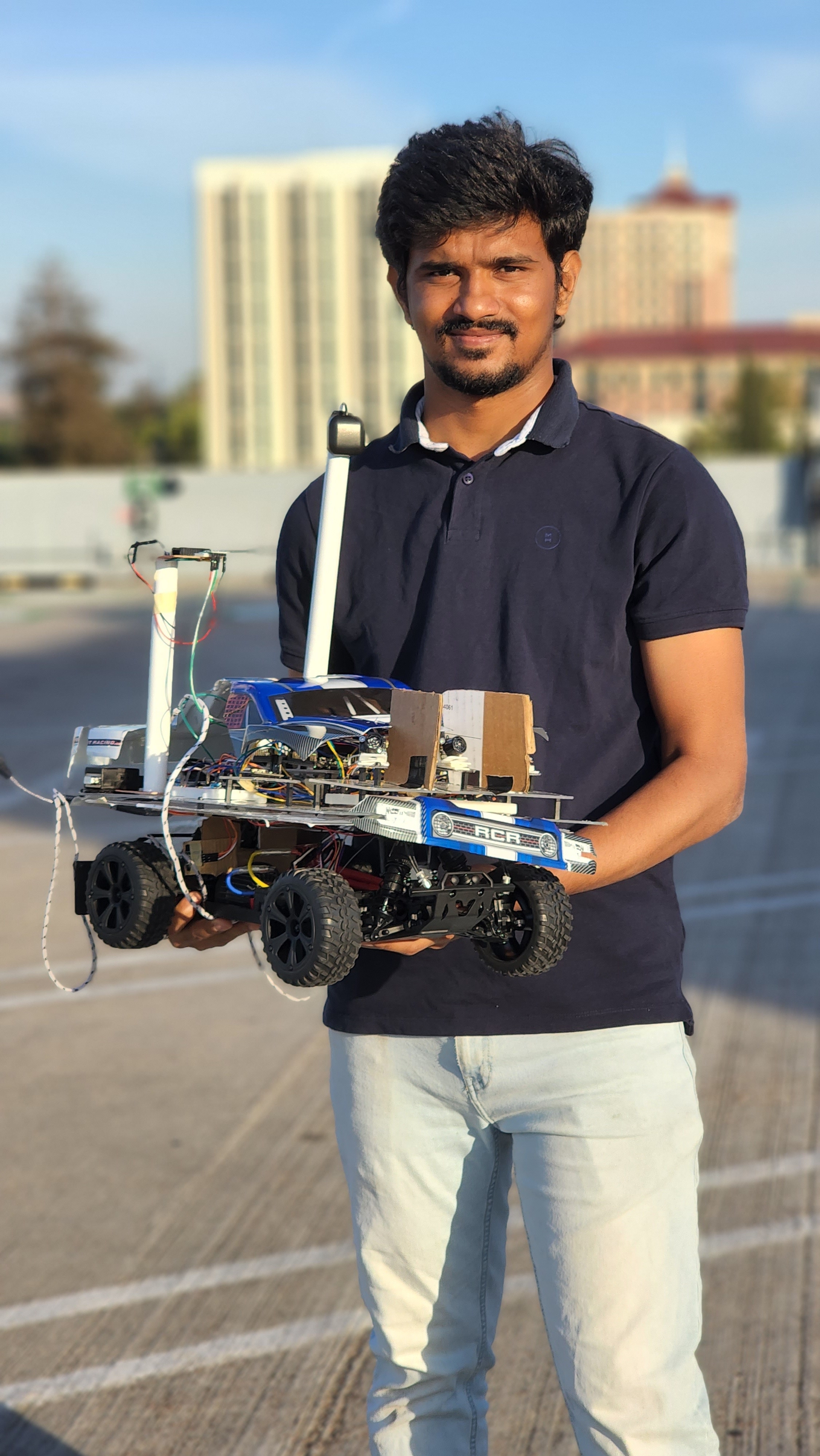
Road Runner is a self navigating car built with the ability to drive to a specified geo-location within its battery range, while avoiding any physical obstacles that come on its way and successfully reaching its destination, with no human intervention apart from commanding the destination location . The car’s infrastructure has four important nodes (Driver, Sensor and Bridge, Geo and Motor) communicating within themselves over internal CAN Bus and with the end user over a mobile application. The car always strives to stay on and maintain its path to the destination by periodically sensing and processing all the relevant information from the nodes to arrive at an informed decision. It is built on top of a hobby grade RC car chassis with all the necessary adjustments and components to achieve its intended objective of self navigating and object avoidance, one of the basic requirements and functionality of an autonomous vehicle.
Introduction
The project was divided into 5 modules:
- Bridge and Sensor Controller
- Motor Controller
- Geo Controller
- Driver / LCD Controller
- Android app interface
Team Members & Responsibilities
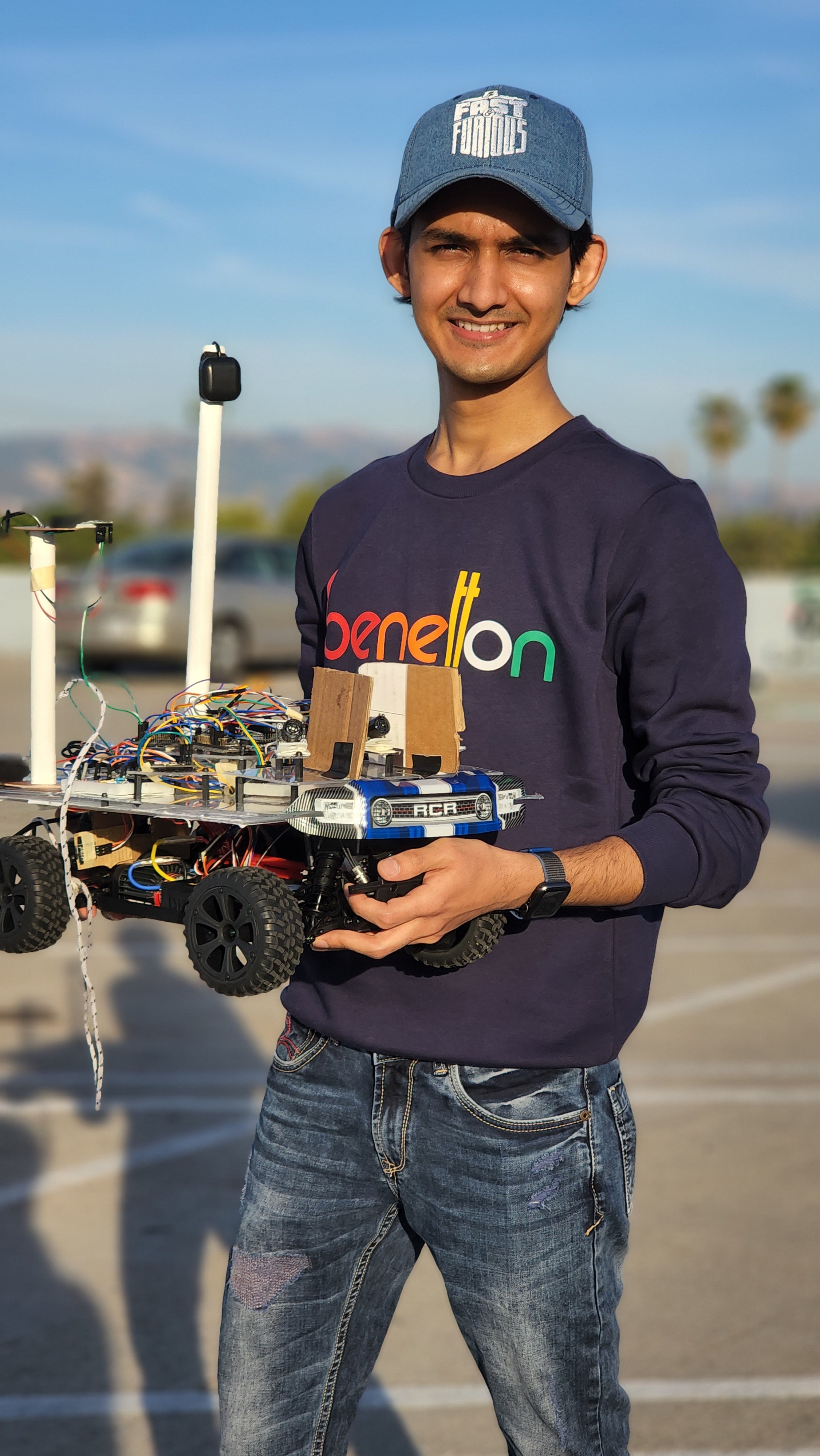
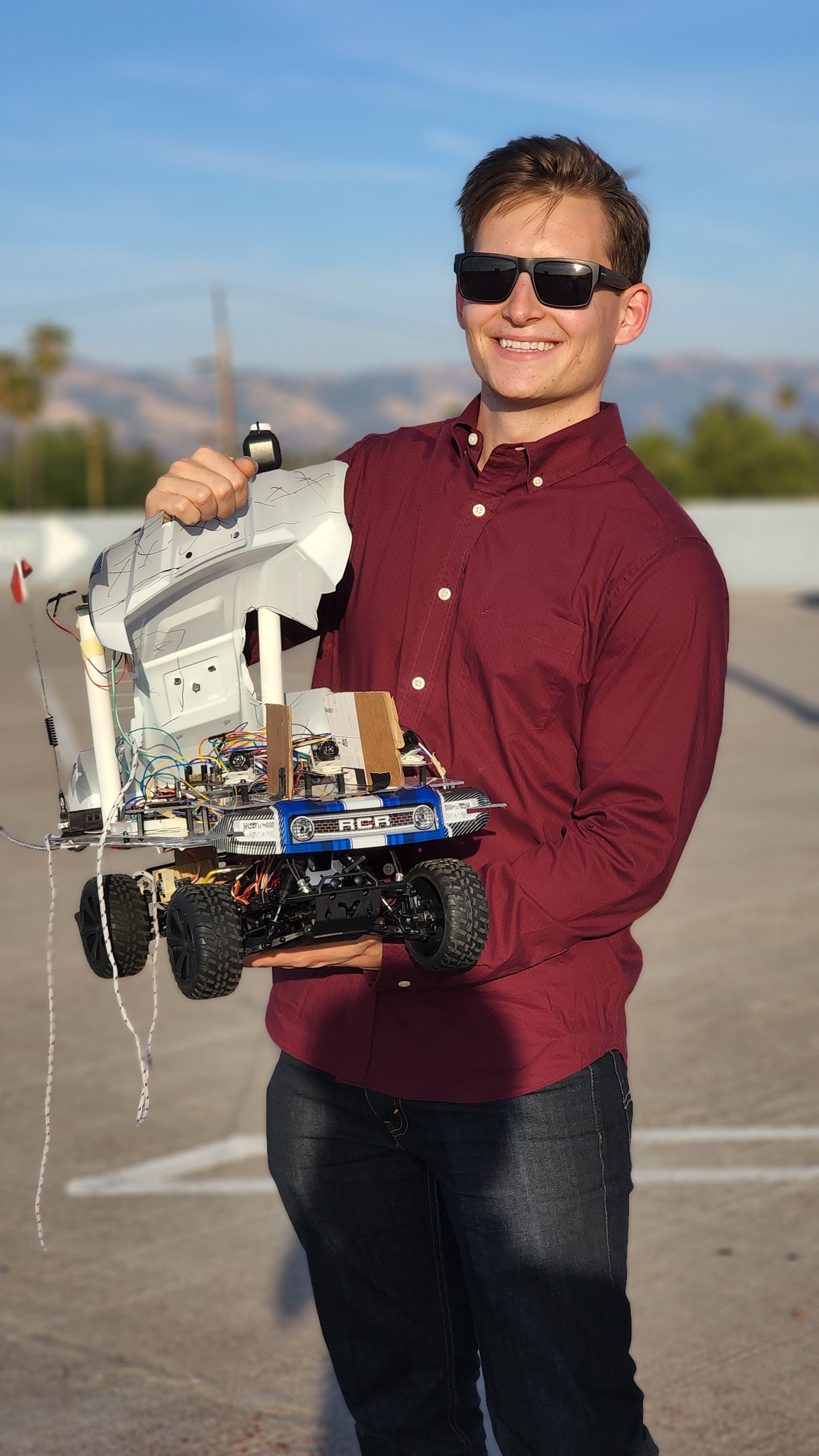
<Team Picture>
Road Runner Firmware: GitLab Repo
- Dhruv Choksi
- Jonathan Doctolero
- Tudor Donca
- Hisaam Hashim
- Saicharan Kadari
- Kyle Kwong
Project Subteams:
- Bridge and Sensor Controller:
- Tudor Donca
- Saicharan Kadari
- Motor Controller:
- Dhruv Choksi
- Hisaam Hashim
- Geological Controller:
- Kyle Kwong
- Jonathan Doctolero
- Saicharan Kadari
- Driver and LCD Controller:
- Hisaam Hashim
- Kyle Kwong
- Android Application:
- Jonathan Doctolero
- Tudor Donca
- Integration and System Testing:
- Tudor Donca
- Dhruv Choksi
- Hisaam Hashim
- Saicharan Kadari
- Kyle Kwong
- Jonathan Doctolero
Schedule
| Week# | Start Date | End Date | Task | Status |
|---|---|---|---|---|
| 1 | 03/06/2022 | 03/12/2022 |
|
|
| 2 | 03/13/2022 | 03/19/2022 |
|
|
| 3 | 03/20/2022 | 03/26/2022 |
|
|
| 4 | 03/27/2022 | 04/02/2022 |
|
|
| 5 | 04/03/2022 | 04/09/2022 |
|
|
| 6 | 04/10/2022 | 04/16/2022 |
|
In Progress |
| 7 | 04/17/2022 | 04/23/2022 |
|
|
| 8 | 04/24/2022 | 04/30/2022 |
|
|
| 9 | 05/01/2022 | 05/07/2022 |
|
|
| 10 | 05/08/2022 | 05/15/2022 |
|
Parts List & Cost
| Item# | Part Description | Vendor | Qty | Cost |
|---|---|---|---|---|
| 1 | RC Car | Redcat [1] | 1 | $153.00 |
| 2 | CAN Transceivers | Various | 6 | $55 |
| 3 | Ultrasonic Sensors | Max Botix[2] | 3 | $134.00 |
| 4 | Adafruit Bluetooth UART Tranceiver | Adafruit[3] | 1 | $33.90 |
| 5 | GPS Module and Antenna | Adafruit[4][5] | 1 | $59.50 |
| 6 | Compass Module | Adafruit[6] | 1 | $29.00 |
| 7 | Wheel Speed RPM Encoder | 1 | ||
| 8 | Discrete Electronic Components | Generic[7] | 1 | $ |
Printed Circuit Board
<Picture and information, including links to your PCB>
CAN Communication
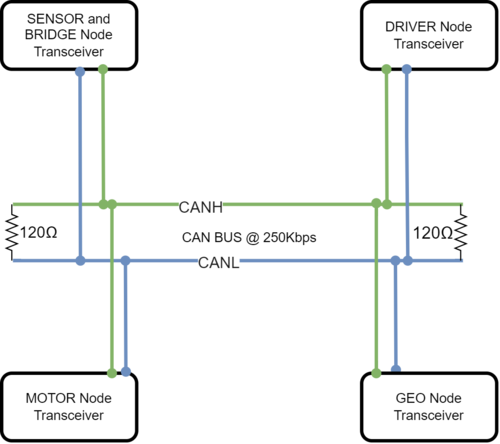
We used CAN Communication setup between all the nodes of the RoadRunner setup. This CAN Bus is terminated with the use of two 120 ohm resistors at both the ends of the Bus. Message IDs were chosen based upon an agreed priority scheme and Bus arbitration scheme. We assigned high priority IDs to messages that controlled the motor, thereby controlling the actual physical movement of the car, followed by sensor and GEO messages, and lowest priority messages were for debug and status messages from the respective nodes . More technical details to fill in..
Hardware Design
<Show your CAN bus hardware design>
DBC File
Gitlab link to the RoadRunner DBC file
VERSION ""

NS_ :
     BA_
     BA_DEF_
     BA_DEF_DEF_
     BA_DEF_DEF_REL_
     BA_DEF_REL_
     BA_DEF_SGTYPE_
     BA_REL_
     BA_SGTYPE_
     BO_TX_BU_
     BU_BO_REL_
     BU_EV_REL_
     BU_SG_REL_
     CAT_
     CAT_DEF_
     CM_
     ENVVAR_DATA_
     EV_DATA_
     FILTER
     NS_DESC_
     SGTYPE_
     SGTYPE_VAL_
     SG_MUL_VAL_
     SIGTYPE_VALTYPE_
     SIG_GROUP_
     SIG_TYPE_REF_
     SIG_VALTYPE_
     VAL_
     VAL_TABLE_

BS_:

BU_: DBG DRIVER MOTOR SENSOR_BRIDGE GEOLOGICAL

BO_ 100 MOTOR_CMD: 4 DRIVER
 SG_ MOTOR_steer_direction : 0|9@1- (1,-2) [-2|2] "steer direction" MOTOR
 SG_ MOTOR_speed_kph : 9|20@1- (0.1,-10.1) [-10.1|10.1] "kph" MOTOR
 SG_ MOTOR_drive_mode : 29|3@1+ (1,0) [0|0] "mode" MOTOR

BO_ 101 MOTOR_STATUS: 4 MOTOR
 SG_ actual_steer_degrees : 0|9@1- (1,-2) [-2|2] "steer direction" DRIVER,DBG
 SG_ actual_speed_kph : 9|20@1- (0.1,-10.1) [-10.1|10.1] "kph" DRIVER,DBG
 SG_ actual_drive_mode : 29|3@1+ (1,0) [0|0] "mode" DRIVER,DBG

BO_ 102 MOTOR_TEST_CONTROL_OVERRIDE: 8 DBG
 SG_ override_steer_pwm : 0|24@1+ (0.01,0) [5.01|15.01] "duty" MOTOR
 SG_ override_motor_pwm : 24|24@1+ (0.01,0) [5.01|15.01] "duty" MOTOR
 SG_ override_enable : 48|1@1+ (1,0) [0|1] "flag" MOTOR

BO_ 200 SENSOR_SONARS: 8 SENSOR_BRIDGE
 SG_ SENSOR_SONARS_left : 0|10@1+ (1,0) [0|500] "cm" DRIVER
 SG_ SENSOR_SONARS_right : 10|10@1+ (1,0) [0|500] "cm" DRIVER
 SG_ SENSOR_SONARS_middle : 20|10@1+ (1,0) [0|500] "cm" DRIVER
 SG_ SENSOR_SONARS_back : 30|10@1+ (1,0) [0|500] "cm" DRIVER

BO_ 201 GPS_DESTINATION: 8 SENSOR_BRIDGE
 SG_ GPS_DESTINATION_latitude : 0|28@1- (0.000001,-90.000000) [-90|90] "Degrees" GEOLOGICAL
 SG_ GPS_DESTINATION_longitude : 28|28@1- (0.000001,-180.000000) [-180|180] "Degrees" GEOLOGICAL

BO_ 202 WAYPOINT: 8 SENSOR_BRIDGE
 SG_ WAYPOINT_latitude : 0|28@1- (0.000001,-90.000000) [-90|90] "Degrees" GEOLOGICAL
 SG_ WAYPOINT_longitude : 28|28@1- (0.000001,-180.000000) [-180|180] "Degrees" GEOLOGICAL

BO_ 203 BRIDGE_CAR_CONTROL: 8 SENSOR_BRIDGE
 SG_ DRIVER_start_stop : 0|1@1+ (1,0) [0|1] "" DRIVER

BO_ 350 GEO_STATUS: 8 GEOLOGICAL
 SG_ GEO_STATUS_COMPASS_HEADING : 0|12@1+ (1,0) [0|359] "Degrees" DRIVER,SENSOR_BRIDGE
 SG_ GEO_STATUS_COMPASS_BEARING : 12|12@1+ (1,0) [0|359] "Degrees" DRIVER,SENSOR_BRIDGE
 SG_ GEO_STATUS_DISTANCE_TO_DESTINATION : 24|24@1+ (1,0) [0|0] "Meters" DRIVER,SENSOR_BRIDGE

BO_ 360 GEO_CURRENT_POSITION: 8 GEOLOGICAL
 SG_ GEO_CURRENT_POSITION_latitude : 0|28@1- (0.000001,-90.000000) [-90|90] "Degrees" DRIVER,SENSOR_BRIDGE
 SG_ GEO_CURRENT_POSITION_longitude : 28|28@1- (0.000001,-180.000000) [-180|180] "Degrees" DRIVER,SENSOR_BRIDGE

BO_ 500 DEBUG_SENSOR_BRIDGE: 8 SENSOR_BRIDGE
 SG_ sensor_left_raw_value : 0|12@1+ (1,0) [0|0] "" DBG
 SG_ sensor_right_raw_value : 12|12@1+ (1,0) [0|0] "" DBG
 SG_ sensor_middle_raw_value : 24|12@1+ (1,0) [0|0] "" DBG
 SG_ sensor_back_raw_value : 36|12@1+ (1,0) [0|0] "" DBG

BO_ 505 DEBUG_MOTOR_CONTROL: 8 MOTOR
 SG_ target_steer_direction : 0|8@1- (1,-2) [-2|2] "steer direction" DBG
 SG_ target_speed_kph : 8|12@1- (0.1,-10.1) [-10.1|10.1] "kph" DBG
 SG_ current_raw_motor_pwm : 20|20@1+ (0.01,0) [5.01|15.01] "duty" DBG
 SG_ current_raw_servo_pwm : 40|20@1+ (0.01,0) [5.01|15.01] "duty" DBG
 SG_ is_override_enabled : 60|1@1+ (1,0) [0|1] "flag" DBG

BO_ 506 DEBUG_MOTOR_RPM: 8 MOTOR
 SG_ computed_rpm : 0|12@1+ (1,0) [0|4000] "rpm" DBG
 SG_ computed_kph : 12|12@1- (0.1,-10.1) [-10.1|10.1] "kph" DBG
 SG_ computed_pid_increment : 24|20@1- (0.01,-5.01) [-5.01|5.01] "duty" DBG
 SG_ total_encoder_tick_count : 44|20@1+ (1,0) [0|0] "ticks" DBG

BO_ 510 DEBUG_DRIVER: 8 DRIVER
 SG_ driver_intention : 0|8@1+ (1,0) [0|0] "" DBG
 SG_ driver_steer_direction : 8|8@1+ (1,0) [0|0] "" DBG
 SG_ driver_drive_direction : 16|8@1+ (1,0) [0|0] "" DBG

CM_ BU_ DRIVER "The driver controller driving the car";
CM_ BU_ MOTOR "The motor controller of the car";
CM_ BU_ SENSOR_BRIDGE "The sensor and bluetooth bridge controller of the car";
CM_ BU_ GEOLOGICAL "The GPS and compass controller of the car";
CM_ BO_ 100 "Sync message used to synchronize the controllers";

BA_DEF_ "BusType" STRING ;
BA_DEF_ BO_ "GenMsgCycleTime" INT 0 0;
BA_DEF_ SG_ "FieldType" STRING ;

BA_DEF_DEF_ "BusType" "CAN";
BA_DEF_DEF_ "FieldType" "";
BA_DEF_DEF_ "GenMsgCycleTime" 0;

BA_ "GenMsgCycleTime" BO_ 100 1000;
BA_ "GenMsgCycleTime" BO_ 200 50;

BA_ "FieldType" SG_ 100 DRIVER_HEARTBEAT_cmd "DRIVER_HEARTBEAT_cmd";
VAL_ 100 DRIVER_HEARTBEAT_cmd 2 "DRIVER_HEARTBEAT_cmd_REBOOT" 1 "DRIVER_HEARTBEAT_cmd_SYNC" 0 "DRIVER_HEARTBEAT_cmd_NOOP" ;

BA_ "FieldType" SG_ 510 driver_intention "driver_intention";
VAL_ 510 driver_intention 1 "DESTINATION_HEADING" 0 "OBSTACLE_AVOIDANCE";

BA_ "FieldType" SG_ 510 driver_steer_direction "driver_steer_direction";
VAL_ 510 driver_steer_direction 2 "TURN_RIGHT" 1 "TURN_LEFT" 0 "STRAIGHT";

BA_ "FieldType" SG_ 510 driver_drive_direction "driver_drive_direction";
VAL_ 510 driver_drive_direction 2 "BACKWARDS" 1 "FORWARDS" 0 "STOPPED";

BA_ "FieldType" SG_ 100 MOTOR_drive_mode "MOTOR_drive_mode";
VAL_ 100 MOTOR_drive_mode 2 "DRIVE_BACKWARDS" 1 "DRIVE_FORWARDS" 0 "NEUTRAL";

BA_ "FieldType" SG_ 100 MOTOR_steer_direction "MOTOR_steer_direction";
VAL_ 100 MOTOR_steer_direction -2 "STEER_MAX_LEFT" -1 "STEER_SLIGHT_LEFT" 0 "STEER_STRAIGHT" 1 "STEER_SLIGHT_RIGHT" 2 "STEER_MAX_RIGHT";
Sensor ECU
<Picture and link to Gitlab>
Hardware Design
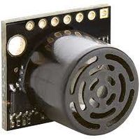
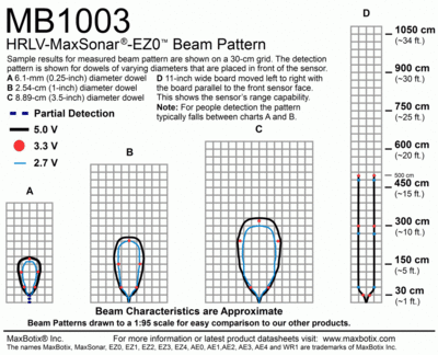
Roadrunner uses three HRLV-MAXSonar-EZ0 MB1003[8] as its eyes and ears on the front. The HRLV-MAXSonar-EZ0 comes in five different models for the ultrasonic sensor. The HRLV-MAXSonar-EZ sensor line is the most cost-effective solution for applications where precision range-finding, low-voltage operation, space-saving, and low-cost are needed. This sensor line features 1mm resolution, target-size and operating-voltage compensation for improved accuracy, superior rejection of outside noise sources, internal speed-of-sound temperature compensation, and optional external speed-of-sound temperature compensation.
These models are the MB1003, MB1013, MB1023, MB1033, and MB1043. The models are based on the beam width of the sensor. It was observed that MB1003 has the optimal beam pattern and was better suited for our objective of object detection. If the beam pattern is too wide given the, there is a greater chance of cross talk between sensors. If the beam pattern is too narrow, there may be blind spots which must be accounted for. Thus, three HRLV-MAXSonar-EZ0 MB1003 sensors were used and the possible unavoidable cross talk is contained by the optimal positioning and software configuration.
Sensor Mounts and Placement
It is decided to place the ultrasonic sensors on 3d- printed mounts and a custom setup to reduce the cross talk and also position them to capture the most field of view and possibly avoid any blind spots for the car movement.
Sensor Readings Extraction
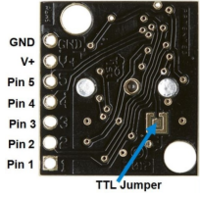
To extract range readings from the MB1003, the "AN" pin which represents analog output was utilized. A range reading is commanded by triggering the "RX" pin high for 20us or more. From the details of the sensor datasheet it is observed that the output analog voltage is based on a scaling factor of (Vcc/512) per inch. As in our setup, all four of the sensors were powered from the SJTWO board, thus a 3.3v VCC was supplied to each sensor. According to the HRLV-MaxSonar-EZ datasheet, with 3.3v source, the analog output was expected to be roughly 6.4mV/inch. However, when initially testing the output range readings, the output was inaccurate. We were thankful for the past students' experiences to notice that the ADC channels for the SJTWO are configured at start-up to have an internal pull up resistor. Disabling this pull up resistor will be discussed more in Software Design and this made the range readings more accurate. The readings were tested by having multiple objects placed in front of each sensor and measuring the distance of the object to the sensors physically. Although the range readings accuracy is improved by the pull-up resistor modification, it was found that the range readings did not necessarily follow the expected 6.4mV/inch. Hence, we decided to calibrate the sensors to xx mV/inch. This value was extracted by placing objects around the sensors and checking if the analog output to inch conversion matched to the actual measured distance.
SJ2 Board Pin Connections with Ultrasonic sensors
Sensors are interfaced with combination of GPIO, ADC Pins on SJTwo board. Below is the descriptive pin layout:
| Sr. No. | SJTwo board Pin | Maxbotix sensor Pin | Function |
|---|---|---|---|
| 1 | ADC2 - P0.25 | AN (Middle sensor) | ADC Input (sensor output) from front sensor |
| 2 | ADC4 - P1.30 | AN (Left Sensor) | ADC input from left sensor |
| 3 | ADC5 - P1.31 | AN (Right Sensor) | ADC input from right sensor |
| 4 | GPIO - P0.6 | RX (Middle Sensor) | Trigger Input for left sensor |
| 5 | GPIO - P0.7 | RX (Left Sensor) | Trigger Input for front sensor |
| 6 | GPIO - P0.8 | RX (Right Sensor) | Trigger Input for right sensor |
Software Design
<List the code modules that are being called periodically.>
Technical Challenges
< List of problems and their detailed resolutions>
Motor ECU
<Picture and link to Gitlab>
Hardware Design
Software Design
<List the code modules that are being called periodically.>
Technical Challenges
< List of problems and their detailed resolutions>
Geographical Controller
<Picture and link to Gitlab>
Hardware Design
Software Design
<List the code modules that are being called periodically.>
Technical Challenges
< List of problems and their detailed resolutions>
Communication Bridge Controller & LCD
<Picture and link to Gitlab>
Hardware Design
Software Design
<List the code modules that are being called periodically.>
Technical Challenges
< List of problems and their detailed resolutions>
Master Module
<Picture and link to Gitlab>
Hardware Design
Software Design
<List the code modules that are being called periodically.>
Technical Challenges
< List of problems and their detailed resolutions>
Mobile Application
Screenshots
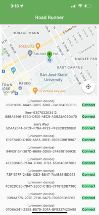
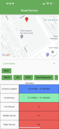
1. The app opens up to show the Google Map with the green marker defaulting to the Engineering Building at SJSU. Once the phone can read the current location of the car, the green marker will update to track the car's location.
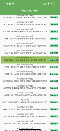
2. The RC Car's Bluetooth Device is named "Adafruit Bluefruit LE" and will be highlighted amongst the list of Bluetooth devices
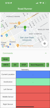
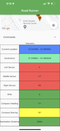
3. Once connected to the RC CAR BLE, the command buttons and telemetry table will appear
4. Pressing the Read button will start reading data from the car and fill the telemetry table with data from the car
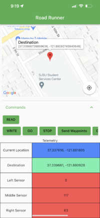
5. Furthermore, a long press on the map will add a destination marker, which the coordinates can be sent to the car by pressing Write
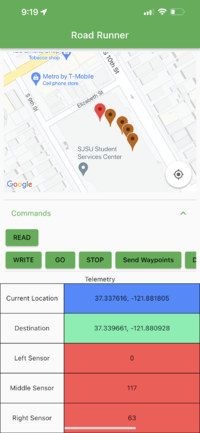
6. Then, waypoints can be added by tapping on the map. The waypoints will be sent once the button "Send Waypoints" is pressed. Also, to clear the waypoints, you need to tap on the info window that appears on the destination marker
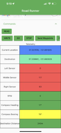
7. Telemetry window shows data read from the SJ2 board, the data is parsed from CAN messages like current location, destination, sensor values, RPM, compass heading and bearing, and distance to destination
8. The buttons can be hidden away to focus on the telemetry table and the map.
Bridge-Sensor Node Firmware Gitlab
Hardware Design
Using the Adafruit BLE Module, we're able to send data from the SJ2 board to the module using UART. Then BLE module then sends the data in packets to the connected mobile phone. By using UART, we can simply print data to the UART to communicate between the Bridge Node and the mobile phone.
Software Design
Code Modules called periodically on the SJ2 board:
- board_processor for reading, parsing and sending data between the SJ2 board and the mobile phone
- can_handler for reading CAN messages on the CAN bus to send telemetry data to the phone and sending CAN messages when reading from the phone
Technical Challenges
- Issue sending more than 20 bytes of data from phone to SJ2 board
 - Resolved by breaking up packets of data into 20 or fewer bytes
- Issue updating telemetry data fast enough
 - Resolved by calling bridge_processor__send_diagnostics_update_periodic() in the 10Hz periodic callback
- Issue handling different data coming into the phone
 - Resolved by hardcoding the fields to fill in the table
Conclusion
<Organized summary of the project>
<What did you learn?>
Project Video
Project Source Code
Advise for Future Students
<Bullet points and discussion>
Acknowledgement
=== References ===
