F20: Jubeat
Contents
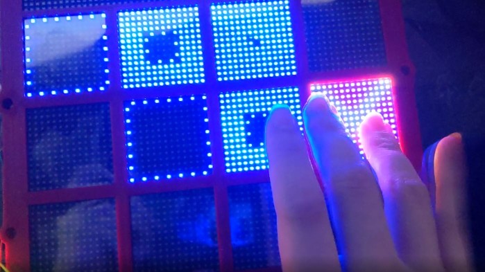
Game photo
Introduction
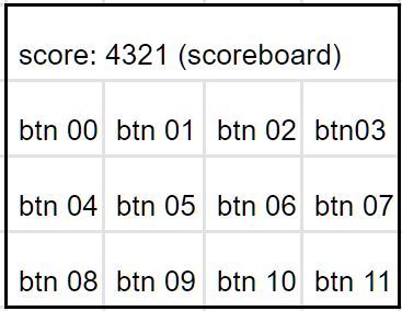
Jubeat is a music game uses an arrangement of a 3x4 grid for the game play. An animation pops up on each grid according to the beat of the song. The player has to use his fingers to tap on the screen and catch the animation in time. The scoreboard locates on the top row of the LED display. Different scores will be given depending on when the player catch the animation. Tapes can be judged as PERFECT, GOOD, OK, and MISS.
Objectives & Introduction
This system:
1. Recognizes finger touch as the input to record the score.
2. Supports real time capacitive touch detection on a LED matrix display.
3. Update corresponding score on the LED display.
4. Outputs the audio via a mp3 module and the soundtracks are stored in an SD card.
Team objectives
1. Understand how each sensor/module works by studying the datasheets to develop an actual product.
2. Understand the proper use of freeRTOS semaphores and event groups in order to send/receive the data between multiple tasks.
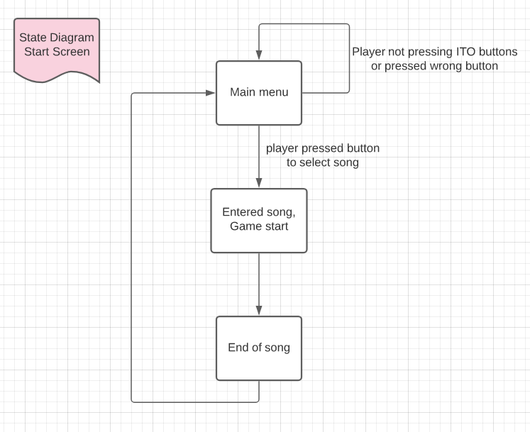
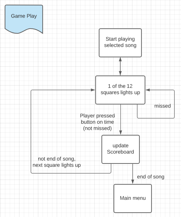
3. Integrate modules and develop smooth game logic. Identify each game state and its transition to next state.
4. Learn how to cooperate codes and logic written by team members through git and branch control.
Team Members & Responsibilities
- Ka In Ng
- Git Admin
- Tyler Tran
- Srikar Narapureddy
Schedule
| Week# | Date | Task | Status |
|---|---|---|---|
| 0 | 10/13/2020 |
|
|
| 1 | 10/21/2020 |
|
|
| 2 | 10/28/2020 |
|
|
| 3 | 11/4/2020 |
|
|
| 4 | 11/11/2020 |
|
|
| 5 | 11/18/2020 |
|
|
| 6 | 11/24/2020 |
|
|
| 7 | 12/1/2020 |
|
|
| 8 | 12/8/2020 |
|
|
Parts List & Cost
| Part Name | Part Model & link | Quantity | Cost Per Unit |
|---|---|---|---|
| Evaluation Board | SJ2 board (NXP LPC4078 MCU) | 1 | $50 |
| 64x64 RGB LED Matrix | 3mm Pitch - 192mm x 192mm | 1 | $59.95 |
| 5V Power Supply | Aclorol 5V 5A 25W AC-DC | 1 | $13.19 |
| 12-Key Capacitive Touch Sensor | Adafruit MPR121 | 1 | $7.95 |
| ITO (Indium Tin Oxide) Coated PET Plastic | 100mm x 200mm | 2 | $9.95 |
| DFPlayer Mini | MakerHawk DFPlayer Mini | 2 | $3.99 |
| Speaker | 3" Diameter - 4 Ohm 3 Watt | 2 | $1.95 |
Design & Implementation
The design section can go over your hardware and software design. Organize this section using sub-sections that go over your design and implementation.
Hardware Design
//Discuss your hardware design here. Show detailed schematics, and the interface here.
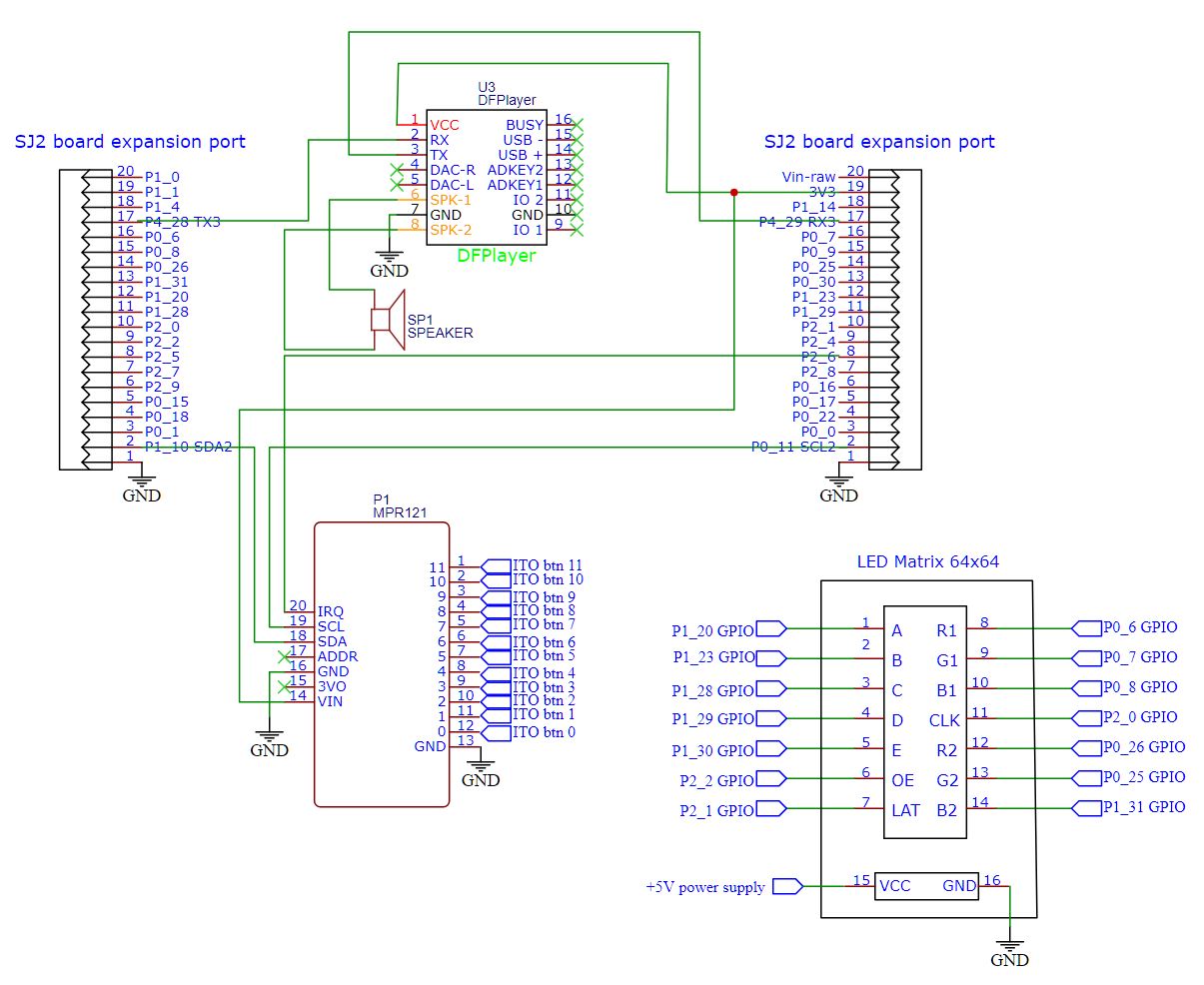
The capacitive touch sensor input pins are wired to 12 pieces of transparent ITO films which are placed on top of each section of the LED matrix display. When the game starts, the song stores in the SD card of the mp3 module starts to play. Animation shows up on any of the 12 LED sections and player has to catch the animation on time to receive scores.
The following schematic shows the wiring of all components.
Hardware Interface
In this section, you can describe how your hardware communicates, such as which BUSes used. You can discuss your driver implementation here, such that the Software Design section is isolated to talk about high level workings rather than inner working of your project.
1. The LED matrix display is connected to the SJ2 board using GPIO ___________________________.
2. The mp3 module is connected to the SJ2 board using UART.
3. The capacitive touch sensor is connected to the SJ2 board using I2C.
Software Design
Show your software design. For example, if you are designing an MP3 Player, show the tasks that you are using, and what they are doing at a high level. Do not show the details of the code. For example, do not show exact code, but you may show psuedocode and fragments of code. Keep in mind that you are showing DESIGN of your software, not the inner workings of it.
Implementation
The 64x64 matrix display is divided into 4 rows, the top row (16x64) is used as a scoreboard, and the remaining rows are divided into 12 square regions, each 16x16 that connects to the ITO buttons that connects to the capacitive sensor for the game input.
LED Driver
Audio Driver
The audio driver is used to play the sound tracks that stored on a SD card of the DFPlayer mp3 module.
1. The DFPlayer mp3 module is connected to the SJ2 board via I2C. Each command takes 10 I2C data transmissions.
2. When the board is turned on, the function audio_init will be called and get ready.
3. The audio_specify_track function is called after the player choose which track to play using the capacitive touch game buttons.
4. Then the audio_start_play function is being called right after.
5. Each audio command contains a 2 byte checksum to maintain the data integrity.
void send_audio_command(uart_e uart, uint8_t audio_command, uint8_t param1, uint8_t param2) {
  uint16_t checksum_2byte = audio_calculate_2byte_checksum(audio_command, param1, param2);
  uint8_t checksum_lowbyte = checksum_2byte;
  uint8_t checksum_highbyte = (checksum_2byte >> 8);
  fprintf(stderr, "checksum = 0x%x, checksum_lowbyte = 0x%x, checksum_highbyte = 0x%x\n", checksum_2byte,
          checksum_lowbyte, checksum_highbyte);

  uint8_t audio_full_command[10] = {start_byte, version_byte, command_length,    audio_command,    feedback,
                                    param1,     param2,       checksum_highbyte, checksum_lowbyte, end_byte};
  for (int i = 0; i < 10; i++) {
    uart__polled_put(uart, audio_full_command[i]);
  }
}
Capacitive touch logic
The capacitive touch sensor is used to identify the finger touch on the ITO button which is transparent and conductive.
1. Each capacitive touch sensor input pin is connected to a ITO film that acts as the game buttons. There are 12 of them throughout the game.
2. When any of the 12 button is being pressed, an interrupt is triggered and we find out the pin that caused the interrupt.
int8_t get_touching_pin(void) {
  uint8_t i;        // i = touching pin number, pin released when i = -1;
  currently_touch = (i2c__read_single(I2C__2, 0xB4, 0x01) << 8); // the MSB 4 input pins (pin 11 - 8)
  currently_touch += i2c__read_single(I2C__2, 0xB4, 0x00);       // add the LSB 8 input pins (pin 7 - 0)
  currently_touch &= 0x0FFF;                                     // remove 4 MSB for slave register 0x01

  for (i = 0; i < 12; i++) {
    if ((currently_touch & (1 << i))) {
      fprintf(stderr, "touching pin %d \n", i);
      return i;
    }
  }
  return -1;
}
Testing & Technical Challenges
Describe the challenges of your project. What advise would you give yourself or someone else if your project can be started from scratch again? Make a smooth transition to testing section and described what it took to test your project.
Include sub-sections that list out a problem and solution, such as:
<Bug/issue name>
Discuss the issue and resolution.
Conclusion
Conclude your project here. You can recap your testing and problems. You should address the "so what" part here to indicate what you ultimately learnt from this project. How has this project increased your knowledge?
Project Video
Upload a video of your project and post the link here.
Project Source Code
References
Acknowledgement
Any acknowledgement that you may wish to provide can be included here.
