S14: Divine WINd
Contents
Grading Criteria
- How well is Software & Hardware Design described?
- How well can this report be used to reproduce this project?
- Code Quality
- Overall Report Quality:
- Software Block Diagrams
- Hardware Block Diagrams
- Schematic Quality
- Quality of technical challenges and solutions adopted.
Divine WINd
Abstract
This section should be a couple lines to describe what your project does.
Objectives & Introduction
Show list of your objectives. This section includes the high level details of your project. You can write about the various sensors or peripherals you used to get your project completed.
Team Members & Responsibilities
- Ryan Marlin
- (Team role)
- Eriberto Velazquez
- (Team Role)
- Devin Villarosa
- (Team Role)
Schedule
| Task | Projected Completion Date | Actual Completion Date | Status | Notes | |
| Buy and Order Parts | 6-Mar | 13-Mar | Complete | Delayed due to researching how to build quadcopter. Ended up ordering a Quadcopter Kit for amateurs' convenience. Parts are ordered from Hong Kong. Customs may take 10+ days plus additional days for shipping (10-30 days). Ordered another kit from U.S. warehouse to complete project on time. | |
| Build Quadcopter | 20-Mar | 26-Mar | Complete | ||
| Install Quadcopter Sensors | 20-Mar | 18-Apr | Complete | ||
| Install Quadcopter Power Unit | 20-Mar | 5-Apr | Complete | ||
| Implement Quadcopter Movement System | 27-Mar | ||||
| Implement Control System Inputs | 3-Apr | ||||
| Implement Control System's Wireless Communication | 10-Apr | ||||
| Implement Quadcopter IP Camera | 17-Apr | ||||
| Implement IP Camera Output on LCD Controller with wireless communication | 24-Apr | ||||
| Test for Demo / Final touches | 1-May | ||||
| Demo | 8-May |
Design & Implementation
The design section can go over your hardware and software design. Organize this section using sub-sections that go over your design and implementation.
Hardware Design
Discuss your hardware design here. Show detailed schematics, and the interface here.
Hardware Interface
In this section, you can describe how your hardware communicates, such as which BUSes used. You can discuss your driver implementation here, such that the Software Design section is isolated to talk about high level workings rather than inner working of your project.
ESC Interface
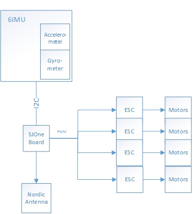
The SJOne board communicates with the ESCs via PWM. The SJOne's PWM output is connected to the white wire of the ESCs 3 pin input. The ground is connected to the black wire, and the ESCs red wire is left hanging, because it is a 5V output. In order to calibrate the ESCs, so that the ESC can produce the range in which the PWM's duty cycle dictates the rate in which the motor produces, the following steps must take place, depending on the ESC manufacturer.
The following steps are used to calibrate this project's ESC:
1) Disconnect power to the ESC
2) Set PWM to an acceptable ESC frequency (between 100hz - 400hz)
3) Set PWM duty cycle to its maximum rating (99%) (This step simulates using a flight controller's transceiver's throttle to the maximum)
4) Plug power to the ESCs
5) Until ESCs gives "beeping signal" in which it accepted its maximum throttle rating, set PWM to lowest throttle (0%) (This simulates using a flight's controller to its minimum throttle).
6) Wait until ESCs "beeps" to signal that accepted minimum throttle is accepted
7) The ESCs has now internally calibrated its throttle acceptance. The user can now send different duty cycle ratings in order to manipulate all motors.
Software Design
Show your software design. For example, if you are designing an MP3 Player, show the tasks that you are using, and what they are doing at a high level. Do not show the details of the code. For example, do not show exact code, but you may show psuedocode and fragments of code. Keep in mind that you are showing DESIGN of your software, not the inner workings of it.
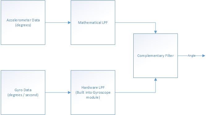
The MPU-9150 consists of a 3-axis accelerometer, 3axis Gyroscope and a 3 axis magnetometer. its a one chip IMU solution with onboard Motion processor for sensor fusion.Though it inherently supports on board Sensor Fusion, the IP is undisclosed. Therefore we used the library for arduino by Pansenti. (https://github.com/Pansenti) The 6 axis sensor fusion (accel+gyro) is done on the MPU and sent to an arduino where the magnetometer data is used for YAW correction. The arduino transmits the orientation data over UART which is recieved by the SJONE for further processing.
For testing, we coded a GUI in python. The code parses the serial data from the arduino and displays the orientation of the IMU in real-time using Vpython.(video and code to be linked).
Implementation
 This section includes implementation, but again, not the details, just the high level. For example, you can list the steps it takes to communicate over a sensor, or the steps needed to write a page of memory onto SPI Flash. You can include sub-sections for each of your component implementation.
Testing & Technical Challenges
Describe the challenges of your project. What advise would you give yourself or someone else if your project can be started from scratch again? Make a smooth transition to testing section and described what it took to test your project.
Include sub-sections that list out a problem and solution, such as:
My Issue #1
Discuss the issue and resolution.
Conclusion
Conclude your project here. You can recap your testing and problems. You should address the "so what" part here to indicate what you ultimately learnt from this project. How has this project increased your knowledge?
Project Video
Upload a video of your project and post the link here.
Project Source Code
Send me your zipped source code and I will upload this to SourceForge and link it for you.
References
Acknowledgement
Any acknowledgement that you may wish to provide can be included here.
References Used
List any references used in project.
https://github.com/Pansenti
https://code.google.com/p/sf9domahrs/
Appendix
You can list the references you used.


