F19: Road Max Fury
Contents
Project Title
Road Max Fury- Game using FreeRTOS
Abstract
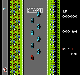
Road Max Fury is a game based on a classic car racing arcade game developed in 1984 by Konami named Road Fighter. We planned to reproduce this game as a part of our CMPE 244 project. The goal is to reach the finish line without running out of time, avoiding other cars on the road or running out of fuel .The fuel is refilled by hitting petrol pump which the player can encounter at random location during the course of the game. The player also needs to prevent car from hitting the edge of the road to prevent the collision.
Objectives & Introduction
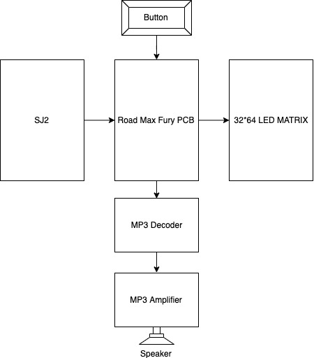
The primary goal of this project is to develop a racing game based on Road Fighter using FreeRTOS using SJ2 Board and to drive the LED matrix. The game's objective is to finish the finish line before running out of fuel and avoiding the obstacles and other cars on the road. The LED matrix is interfaced using the GPIO pins and the on board accelerometer is interfaced using I2C communication protocol.
Objectives:
- Write drivers to display road, car, traffic, score, fuel status on the RGB LED matrix and update the display continuously.
- Write drivers to give directions from the input devices ie accelerometer and filter the values to get accurate and desired values.
- Implement game algorithm for movement of car, random obstacle car and update scores and fuel status.
- Create FeeRTOS tasks for display, accelerometer values, game logic and understand the communication and synchronization between them.
Team Members & Responsibilities
Schedule
| Week# | Date | Deliverables | Status |
|---|---|---|---|
| 1 | 09/29 |
|
|
| Week# | Date | Deliverables | Status |
| 2 | 10/12 |
|
|
| Week# | Date | Deliverables | Status |
| 3 | 10/16 |
|
|
| Week# | Date | Deliverables | Status |
| 4 | 10/23 |
|
|
| Week# | Date | Deliverables | Status |
| 5 | 10/30 |
|
|
| Week# | Date | Deliverables | Status |
| 6 | 11/06 |
|
|
| Week# | Date | Deliverables | Status |
| 7 | 11/13 |
|
|
| Week# | Date | Deliverables | Status |
| 8 | 11/24 |
|
|
| Week# | Date | Deliverables | Status |
| 9 | 12/1 |
|
|
| Week# | Date | Deliverables | Status |
| 10 | 12/8 |
|
|
| Week# | Date | Deliverables | Status |
| 11 | 12/13 |
|
|
Parts List & Cost
Design & Implementation
Hardware Design
LED MATRIX
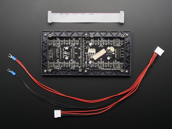
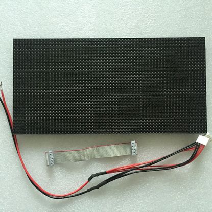
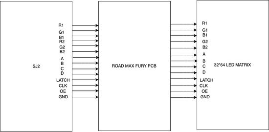
The hardware design employs the use of 64x32 RGB LED matrix panel which is the most important part of the project, this uses four data lines namely A, B, C and D which can be addressed and used to control each LED which has following technical specifications:
Dimensions:
- 110.1 x 5 x 0.2 inches
Operation Power
- AC100-240V 50-60HZ Switch-able
- 5V regulated power input, 4A max (all LEDs on)
- 5V data logic level input
- 4mm pitch
- Module Refresh: 1560hz
LED MATRIX DRIVER AND IMPLEMENTATION
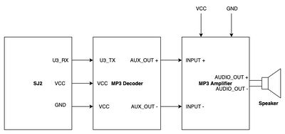
MP3 DECODER AND AMPLIFIER
PCB Design
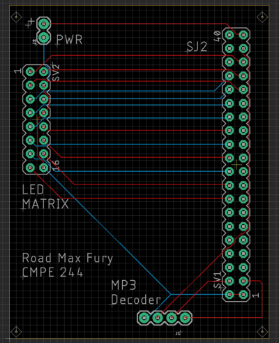
For PCB Design we used the Eagle PCB Design software. It is not free software for commercial use but is free for students. Preet took a short session on PCB designing which helped to get us started. A great advantage of Eagle PCB is that we can importAdafruit and Sparkfun library into the PCB Design software. This allows us to use the built-in footprints and schematic components of Sparkfun and Adafruit which makes designing and ordering the parts easier. The software is easy to use for a beginner.
The steps involved in the PCB design process are described in the next section.
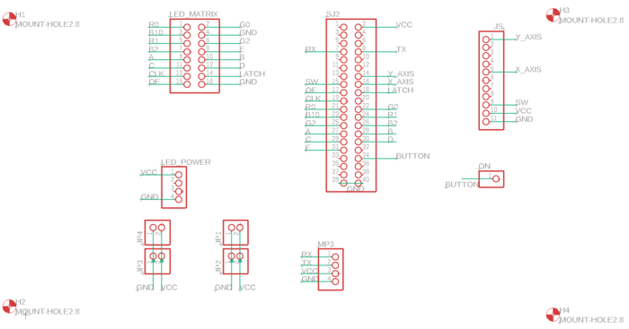
Schematic Design:
Our Schematic is simple. We added header pins, for making connections from the LED matrix, MP3 decoder to SJ2 board and external power pins. A 2x1 header is used to for connecting external power. 20x2 header pin is used to connect the SJ2 board GPIO pins. 8x2 header pins are used to connect the LED Matrix Pins. 4x1 header is used for connecting the MP3 decoder to a UART3 GPIO pin.
PCB Layout Design:
In our PCB layout, we used 2-layered PCB (A top layer and a bottom layer). PCB traces are made in a vertical, horizontal and at 45-degree angles for a consistent layout. The top layer is traces are in RED color and the bottom layer traces are in BLUE color. Labels and markings are added for identify components and pin numbers. After completing the PCB layout (making the traces) we then performed Design Rule Check (DRC) to verify that there are no short or open connections. Finally, we generated Gerber File and sent it to JLC PCB for manufacturing.
Display Module
RGB LED Matrix:
| SJ One Board Pin | Name | Description |
|---|---|---|
| P1_14 | R1 | Top half red data |
| P4_29 | G1 | Top half green data |
| P0_7 | B1 | Top half blue data |
| P4_28 | R2 | Bottom half red data |
| P0_6 | G2 | Bottom half green data |
| P0_8 | B2 | Bottom half blue data |
| P0_26 | addrA | Address Input A |
| P1_31 | addrB | Address Input B |
| P1_20 | addrC | Address Input C |
| P1_28 | addrD | Address Input D |
| P2_0 | Clock | Shift clock |
| P2_2 | Latch | Shift in row data/Active High |
| P2_5 | Output Enable | Turn on selected rows/Active Low |
Software Design
We have four tasks
Game Task
Accelerometer Task
Button Input Task
MP3 player Task
Accelerometer
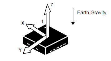
We used on-board accelerometer to get the values. We have used only the Y-axis values to trigger movement of the player's car. We have divided the Y-axis values into different buckets which defines where the player car should move.
Code Snippet
static void accelerometer_task(void *params) {

  acceleration__axis_data_s acc_sensor_values;
  uint32_t y = 0;
  while (1) {
    acc_sensor_values = acceleration__get_data();
    y = acc_sensor_values.y;

    switch (y) {
    case 0 ... 150: //Staright
      break;

    case 151 ... 800: //Right
      move_car_right();
      break;

    case 3100 ... 3944: //Left
      move_car_left();
      break;

    case 3945 ... 4095: //Straight
      break;

    default:
      break;
    }
    vTaskDelay(50);
  }
}
Random Obstacle Generator and Movement
For every level we have new obstacles in addition with the old ones. We have an array of obstacle types and we select specific obstacles based on the level. We are using rand() to select the X-axis coordinate and to select the type of obstacle to generate.
Code Snippet
static void generate_obstacle(bitmap_object *obstacle) {
  uint8_t x, index;

  obstacle->y = BORDER_HEIGHT - CAR_HEIGHT_WITH_PADDING;

  x = rand() % LED_MATRIX_WIDTH;
  if (x < BORDER_WIDTH) {
    x = BORDER_WIDTH;
  } else if (x > (LED_MATRIX_WIDTH - BORDER_WIDTH - CAR_WIDTH_WITH_PADDING)) {
    x = LED_MATRIX_WIDTH - BORDER_WIDTH - CAR_WIDTH_WITH_PADDING;
  }
  obstacle->x = x;

  index = rand() % levels[current_level - 1].level_obstacle_mod;

  obstacle->image = obstacle_types[index].image;
  obstacle->isAlive = true;
  obstacle->color = obstacle_types[index].color;
  obstacle->movement_type = obstacle_types[index].movement_type;
  obstacle->height = obstacle_types[index].height;
  obstacle->width = obstacle_types[index].width;
  obstacle->speed = obstacle_types[index].speed;
  obstacle->counter = 0;
  obstacle->direction = index % 2;
}
Every object has padding above it and on the left and right. When we move the obstacle down by one row, the padding clears the last row. For every obstacle there are three attributes speed, life and movement type. We update the position of the obstacle when the counter reaches the corresponding speed. We have two movement types DOWN and DOWN_AND_LEFT_RIGHT. We update the counter every 30ms. So if the speed of the car is 20, then the car moves down every 30*20 = 600ms. In case of DOWN_AND_LEFT_RIGHT, we update the X-axis as well as Y-axis values. The alive attribute is set to false once the obstacle is out of the screen.
Code Snippet
static void move_obstacles(bitmap_object *obstacle) {
  obstacle->counter++;
  if (obstacle->counter < obstacle->speed) {
    return;
  }

  switch (obstacle->movement_type) {
  case DOWN:
    obstacle->y = obstacle->y - 1;
    break;
  case DOWN_AND_LEFT_RIGHT:
    obstacle->y = obstacle->y - 1;
    if (obstacle->direction == RIGHT) {
      if (obstacle->x <
          (LED_MATRIX_WIDTH - BORDER_WIDTH - CAR_WIDTH_WITH_PADDING)) {
        obstacle->x = obstacle->x + 1;
      } else {
        obstacle->direction = LEFT;
      }
    } else {
      if (obstacle->x > BORDER_WIDTH) {
        obstacle->x = obstacle->x - 1;
      } else {
        obstacle->direction = RIGHT;
      }
    }
  }

  if (obstacle->y == (-1) * CAR_HEIGHT_WITH_PADDING) {
    obstacle->isAlive = false;
    num_of_on_screen_obstacles--;
  }
}

void move() {
  for (uint8_t i = 0; i < NUM_OF_OBSTACLES; i++) {
    if (car_obstacle[i].isAlive) {
      move_obstacles(&car_obstacle[i]);
    }
  }
}
Testing & Technical Challenges
Issues, Challenges and solutions to get past them
1. RGB LED Matrix Display driver
We first started by porting Adafruit’s LED driver for Arduino, however we could not get it running. So we started to implement our own driver. It worked well for the bottom half of the matrix but not the top half. We debugged the code, later to realize that the SJ2 board pins which we were using for R1, G1 and B1 were not working properly. We used other GPIO pins and it solved the issue.
2. MP3 Decoder The HiLetgo YX5300 UART Control Serial MP3 Music Player Module does not have a detailed datasheet available for reference. After much researching on the internet we found a catalex_mp3 decoder data sheet which was really helpful in understanding and using the mp3 decoder.
3. Low level Audio Sound As we wanted to make the game package very compact, we opted for low power magnetic speaker which consumes less power and does not require an external power source. But when we started using this speakers we noticed that audio level was very low. We used an audio amplifier which takes in the output of the mp3 decoder and amplifies and sends it to the speaker. The onboard potentiometer on this amplifier can be used to adjust the level of the output volume.
4. Pause Bug When we paused the game, the display was frozen but after hitting the play button, the position of the car was way off when we paused. We realized that our accelerometer kept updating the position of the car, it was just not displayed. To solve this issue we now update the values only in the GAME PLAY state.
Conclusion
We were able to successfully design the Road Max Fury game using the RGB LED Matrix and the SJ2 board. This project helped us in having a better understanding of the FreeRTOS scheduler tasks that were used to handle the various components of the game. The understanding developed in writing the display driver from the scratch proved beneficial in resolving issues since most of the available libraries are in C++ and we encountered many problems while porting and debugging in the initial testing phase. Even though there weren't many proper datasheets and reliable tutorials for the LED Matrix, some previous semester's project report on the same display helped us gain momentum in the initial stages. We also got to work on the MP3 decoder while incorporating audio for the game design. Not only did this project help us in understanding the practical possibilities with boards like SJ2 board but also instilled in us a sense of team work and accountability for individually assigned task that helped the team overall.
Project Video
Upload a video of your project and post the link here.
