F18: Flappy Bird
Contents
Project Title
Flappy Bird - Game using FreeRTOS
Abstract
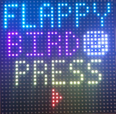
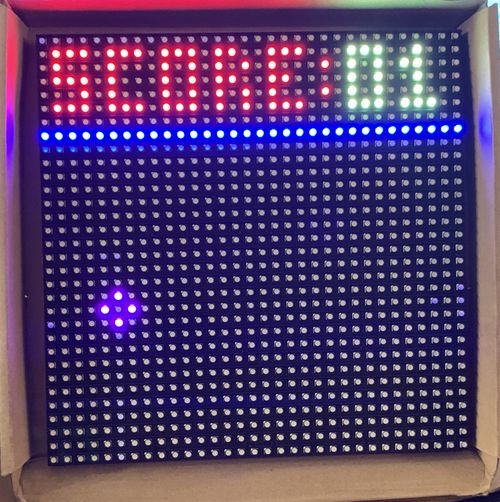
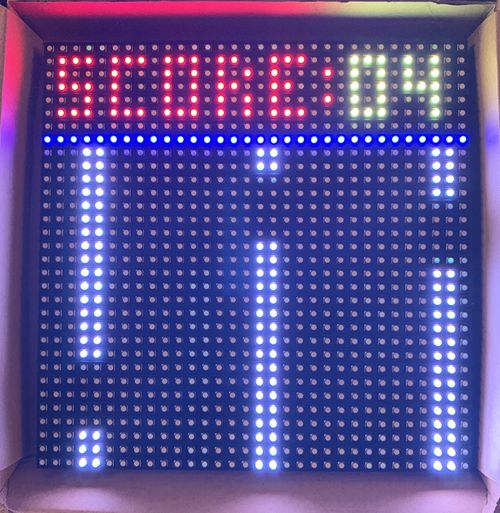
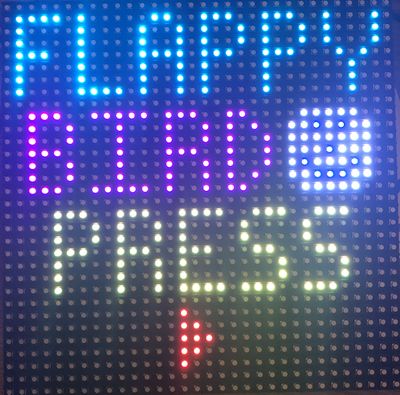
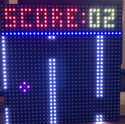
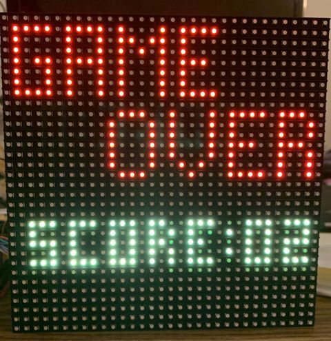
Flappy Bird is a fun and intuitive mobile game on Android platform driving a lot of people crazy these days. In this game, the player can control the movement of the bird. Pressing the button makes the bird leap upward and on releasing the button the bird will fall freely. In the proposed game design, as soon as the game begins, obstacles will keep appearing from the right side of the screen and move leftwards which will make bird seem to be flying in the forward direction. The goal of this game would be to control the bird, dodging and passing it through as many obstacles as possible. This will run endlessly until the bird hits the obstacle, ground or ceiling. At the beginning of the game, the player is prompted to hit the play button to start the game. Once the Bird is unable to beat the obstacle, the game is concluded and the score for that session is displayed.
Objectives & Introduction
Flappy Bird was designed as a 2D game with simplicity in mind. Hence the primary objective was to develop a game that was a breeze to use for the end user. The push button interfaced with SJ One board acts as an interface between the user and the device which enables the control of the movement of the bird and helps it maneuver and skip the incoming obstacles. The bird continues to gradually descend and reach the bottom of the screen unless an input from the user helps it to fly upwards. The signals received from the button are relayed to the micro controller form the General Purpose I/O Pins. This input is read repeatedly and based on which the x co-ordinate of the bird gets incremented. In parallel the Obstacles are generated with random varying gaps for the bird to pass through them. The game is especially challenging when the user has take care of not letting the bird escape the screen space as well as dodging as many obstacles as possible in order to beat the high score. However, if the either of the challenges are not tackled, the game finishes and displays the current score. There are three components to the entire project:
- The Display : A 32x32 LED Display Matrix acts as the display of the game which is handled using the in-built GPIO pins provided by the manufacturer
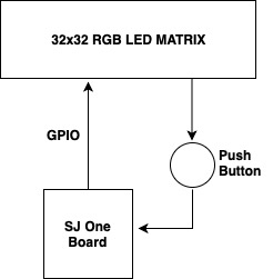
- The Controller : The SJ One Board computes the random obstacle generation and handles the movement of the bird from the input button and transfers the information to the display using the GPIO pins
- The Button : The push button interfaced with the game reads the input given by the user and relays to the SJ One board
Team Members & Responsibilities
- Karan Daryani
- PCB Layout Designing
- Obstacle generation driver design
- Artik Shetty
- Bird generation driver design
- Hardware and Product enclosure design
- Mahesh Shinde
- Managing Wiki page
- Collision detection driver design
- Rachit Mathur
- Code Integration(overall tasks integration)
- Switch control implementation
Schedule
| Week# | Date | Task | Status | Actual Completion Date |
|---|---|---|---|---|
| 1 | 09/18/2018 |
|
|
|
| 2 | 10/9/2018 |
|
|
|
| 3 | 10/16/2018 |
|
|
|
| 4 | 10/23/2018 |
|
|
|
| 5 | 10/30/2018 |
|
|
|
| 6 | 11/06/2018 |
|
|
|
| 7 | 11/13/18 |
|
|
|
| 8 | 11/20/18 |
|
|
|
| 9 | 11/27/18 |
|
|
|
| 10 | 12/04/18 |
|
|
|
| 11 | 12/08/18 |
|
|
|
Parts List & Cost
| Item# | Part | Manufacturer | Quantity | Cost($) |
|---|---|---|---|---|
| 1 | SJ One Board | Preet | 1 | 80.00 |
| 2 | Adafruit RGB LED Matrix | Adafruit | 1 | 62.00 |
| 3 | Power Adapter | Power Supply | 1 | 7.95 |
| 4 | JLC PCB | JLC PCB | 1 | 22.00 |
| 6 | Miscellaneous (Jumper Wires, Connectors, Switches) | Excess Solution | 2.00 |
- Total Cost: $173.95
Design & Implementation
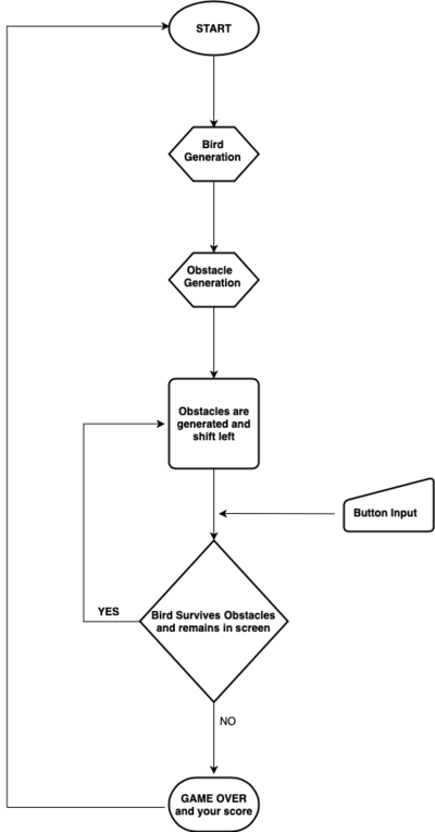
The block diagram for the project given below depicts the flow of the game
Hardware Design
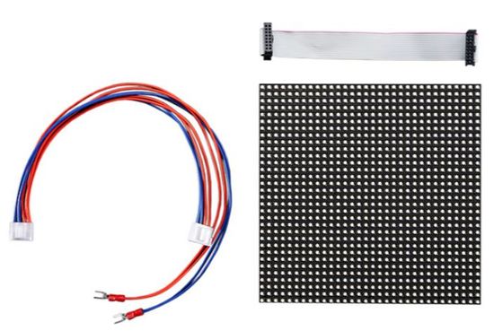
The hardware design employs the use of 32x32 RGB LED matrix panel which is the most important part of the project, this uses four data lines namely A,B,C and D which can be addressed and used to control each LED which has following technical specifications:
Dimensions:
- 190.5mm x 190.5mm x 14mm / 7.5" x 7.5" x 0.55"
- Panel weight with IDC cables and power cable: 357.51g
- 5V regulated power input, 4A max (all LEDs on)
- 5V data logic level input
- 2000 mcd LEDs on 6mm pitch
- 1/16 scan rate
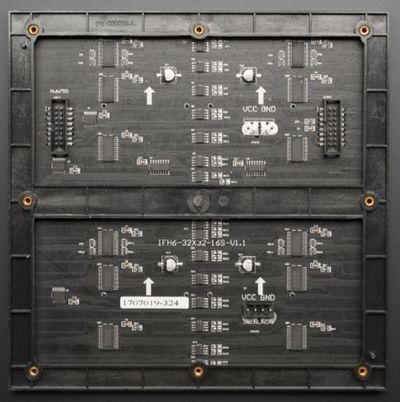
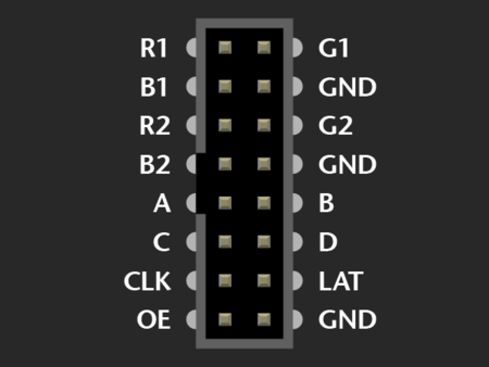
The figure and table below shows the pin-out of RGB LED matrix with description.
| Label | Name | Function |
|---|---|---|
| 1 | R1 | High R data |
| 2 | G1 | High G data |
| 3 | B1 | High B data |
| 4 | R2 | Low R data |
| 5 | G2 | Low G data |
| 6 | B2 | Low B data |
| 7 | A | A line selection |
| 8 | B | B line selection |
| 9 | C | C line selection |
| 10 | D | D line selection |
| 11 | CLK | CLOCK |
| 12 | LAT | LATCH |
| 13 | OE | Output Enable |
| 14 | GND | GND |
LED Matrix Control
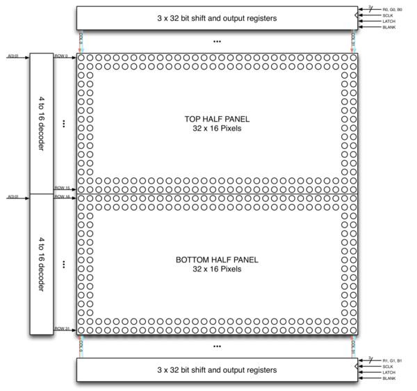
The LED panel contains 1024 RGB LEDs arranged in a matrix of 32 rows and 32 columns. Each RGB LED contains separate red, green, and blue LED chips assembled together in a single package. The display is subdivided horizontally into two parts, the top half and bottom half consists of 32 columns and 16 rows respectively.
There are different drivers for controlling display’s columns and another set of drivers for controlling rows. To illuminate an LED, the drivers for both the column and the row for that LED must be turned on. To change the color of an LED, the red, green, and blue chips in each LED package are controlled individually and have their own column drivers.
The panel contains six sets of column drivers; three for the top half of the display and three for the bottom. Each driver has 32 outputs. The three drivers for the top of the display drive the red, green, and blue chips in each of the 32 columns of LEDs in rows 0 to 15 of the panel. The three drivers for the bottom of the display drive the red, green, and blue chips in each of the 32 columns of LEDs in rows 16 to 31 of the panel. The red, green, and blue column drivers for the top half of the display are attached respectively to the R0, G0, and B0 data inputs. The red, green, and blue column drivers for the bottom half of the display are attached respectively to the R1, G1, and B1 data inputs. All six of the 32-bit drivers share common SCLK, LATCH, and BLANK signals.
The display is multiplexed and has a 1/16th duty cycle. This means that no more than one row out of the 16 in the top half of the display and one row out of the 16 in the bottom half of the display are ever illuminated at once. Furthermore, an LED can only be on or off. If both the row and column for an LED are turned on, the LED will be illuminated; otherwise, the LED will be off. To display an image, the entire LED panel must be scanned fast enough so that it appears to display a continuous image without flickering. To display different colors and different brightness levels, the brightness of the red, green, and blue LED chips within each LED package must be adjusted by varying the amount of time that each LED chip is on or off within a single refresh cycle.
Hardware Interface
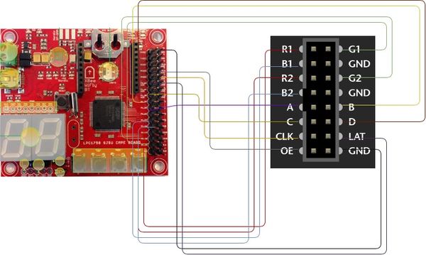
The SJ One Board connects to the LED Matrix as well as the external push button through the on-board GPIO pins available.
|
Software Design
The entire software for the game including the APIs were written from scratch. A thorough understanding of the LED Display Matrix proved beneficial in writing suitable code for the display.
Logic
A matrixbuf array maps onto the LED Display Matrix. A value overwritten in this two-dimensional buffer updates the corresponding Pixel value of the LED Matrix. The drawPixel function maps onto the matrixbuf and updates the corresponding value.
There are different tasks that handle the generation of the bird, generation of obstacles, detection of collision, shifting of obstacles as well as maintaining the scoring of the game. These tasks run in parallel and are scheduled with the help of of the task scheduler that updates the display regularly
There were three algorithms that were designed for the implementation of the game
1. Bird Generation Algorithm
The bird generation is simple and straight forward where the row and column are given as inout parameters to the drawPixel function which writes these values to the matrix buffer.
However complexity increases when the input of the button determines the position of the bird and the limit for the collision are checked with boundaries of the available screen estate.
void LedMatrix::drawBird(uint8_t row, uint8_t col){
    if(birdRow != 0 && birdCol != 0){
        if(row<16){
            drawPixel(row,col,0x5);
            drawPixel(row,col-2,0x5);
        } else {
            drawPixel(row,col,0x28);
            drawPixel(row,col-2,0x28);
        }
        if( (row-1) < 16){
            drawPixel(row-1,col-1,0x5);
        } else {
            drawPixel(row-1,col-1,0x28);
        }
        if( (row+1) < 16){
            drawPixel(row+1,col-1,0x5);
        } else {
            drawPixel(row+1,col-1,0x28);
        }
    }
}
2. Obstacle Generation Algorithm
A random number determines the placement of gap between the obstacles for the bird to escape through. Depending on the value of random gap generated, the matrix buffer is updated and subsequently the obstacle is displayed.
void LedMatrix::generateObstacle(){
    for(uint8_t col=0;col<32;col++){
        if ( obsarray[col] != 0){
            uint8_t obsHeight = obsarray[col];
            for(uint8_t x=8 ;x<32;x++){
                if ((x == obsHeight))
                {
                    x+=4;
                } else{
                    if (x<16){
                        matrixbuf [x][col] += 0x7;
                    }
                    else {
                        matrixbuf [x][col] += 0x38;
                    }
                }
            }
        }
    }
}
3. Collision Detection Algorithm
The bird continues to hover over the screen space unless it collides with the incoming obstacles or runs out of the screen space. In such a case, the game is stopped and the high priority end game screen is displayed.
bool LedMatrix::detectCollision(){
    if( birdRow < 10 || birdRow > 29){
        birdRow = 0;
        birdCol = 0;
        cleanDisplay();
        for(int i=0;i<32;i++){
            obsarray[i] = 0;
        }
        return true;
    }
    else {
        for(int col=4; col<7; col++){
            for(int row=0; row<16; row++){

                if (matrixbuf[row][col] == 0x0C){
                    birdRow = 0;
                    birdCol = 0;
                    cleanDisplay();
                    for(int i=0;i<32;i++){
                        obsarray[i] = 0;
                    }
                    return true;
                }
                if (matrixbuf[row+16][col] == 0x60){
                    birdRow = 0;
                    birdCol = 0;
                    cleanDisplay();
                    for(int i=0;i<32;i++){
                        obsarray[i] = 0;
                    }
                    return true;
                }

            }
        }
    }
    return false;
}
Implementation
As described earlier, various tasks related to generation of bird, generation of obstacles, detection of collision and shifting of the obstacles run in parallel. These tasks are maintained by the task scheduler implementation of which is depicted below in the following code snippet.
class gameStart: public scheduler_task
{
public:
    gameStart(uint8_t priority): scheduler_task("gameStart", 2048, priority){
        reset.setAsInput();
    }
    bool run(void *p)
    {
        Matrix.updateDisplay2();
        if(reset.getLevel() == 1){
            Matrix.clearDisplay();
            Matrix.gameStart();
            printf("Suspended the task");
            Matrix.birdCol = 6;
            Matrix.birdRow = 14;
            suspend();
        }
        return true;
    }
};

class updateDisplayTask: public scheduler_task
{
public :
    updateDisplayTask(uint8_t priority): scheduler_task("updateDisplay", 2048, priority){
        }
        bool run(void *p)
        {
            Matrix.updateDisplay();
            return true;
        }
};

class shiftLeftTask: public scheduler_task
{
public :
    shiftLeftTask(uint8_t priority): scheduler_task("shiftLeft", 2048, priority){
        }
        bool run(void *p)
        {
            Matrix.shiftleft();
            delay_ms(delay);
            return true;
        }
};

class rotateLeftTask: public scheduler_task
{
public :
    rotateLeftTask(uint8_t priority): scheduler_task("rotateLeft", 2048, priority){
        }
        bool run(void *p)
        {
            Matrix.rotateleft();
            delay_ms(delay);
            return true;
        }
};

class drawObstacleTask: public scheduler_task
{
public :
    drawObstacleTask(uint8_t priority): scheduler_task("drawObstacle", 2048, priority){
        }
        bool run(void *p)
        {
            Matrix.drawObstacle();
            delay_ms(delay*13);
            return true;
        }
};

class gameBird: public scheduler_task
{
public :
    gameBird(uint8_t priority): scheduler_task("gameBird", 2048, priority){
        }
        bool run(void *p)
        {
            Matrix.gameBird();
            return true;
        }
};

class gameOver: public scheduler_task
{
public :
    gameOver(uint8_t priority): scheduler_task("gameOver", 2048, priority){
        }
        bool run(void *p)
        {
            Matrix.gameOver();
            Matrix.updateDisplay2();
            return true;
        }
};

class detectCollision: public scheduler_task
{
public :
    detectCollision(uint8_t priority): scheduler_task("detectCollision", 2048, priority){
    }
    bool run(void *p)
    {
        bool result = 0;
        result = Matrix.detectCollision();
        if( result == 1 ){
            printf("Collison Detected \n");
            Matrix.updateDisplay2();
            scheduler_task *updateDisplay= getTaskPtrByName("updateDisplay");
            if(NULL != updateDisplay){
                vTaskSuspend(updateDisplay->getTaskHandle());
            }
            scheduler_task *gameBird= getTaskPtrByName("gameBird");
            if(NULL != gameBird){
                vTaskSuspend(gameBird->getTaskHandle());
            }
            scheduler_task *drawObstacle= getTaskPtrByName("drawObstacle");
            if(NULL != drawObstacle){
                vTaskSuspend(drawObstacle->getTaskHandle());
            }
            scheduler_task *shiftLeft= getTaskPtrByName("shiftLeft");
            if(NULL != shiftLeft){
                vTaskSuspend(shiftLeft->getTaskHandle());
            }
            scheduler_task *displayScore= getTaskPtrByName("displayScore");
            if(NULL != displayScore){
                vTaskSuspend(displayScore->getTaskHandle());
            }
            suspend();
        }
        delay_ms(delay);
        return true;
    }
};

class displayScore: public scheduler_task
{
public:
    displayScore(uint8_t priority): scheduler_task("displayScore", 2048, priority){
    }
    bool run(void *p)
    {
        Matrix.displayScore();
        delay_ms(delay);
        return true;
    }
};
Printed Circuit Board Design
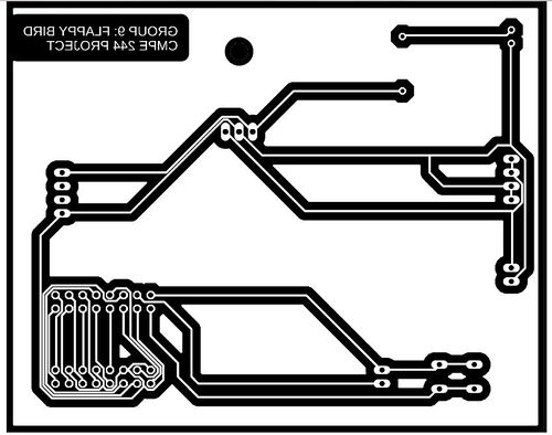
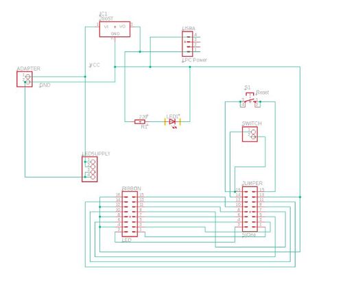
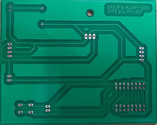
We have designed and developed a PCB in order to supply power for SJOne board and RGB LED Matrix which is able to provide 5v and 1A supply efficiently. The PCB Layout is designed using the Eagle Software v9.2.2. The Power Supply circuit has an IC7805 voltage regulator IC and a voltage divider to fulfill the specific power requirements. IC7805 is a linear voltage regulator which has a variable output voltage ranging from 4.8 V to 5.2 V and is suitable for our application. We have used a 5V adapter in order to power our board. This serves for both the current requirements. The circuit was simulated using MultiSim v14.1 software by NI (National Instruments). The simulation helped us understand the working of our circuit before we built and tested it.
Technical Challenges
Display Driver Implementation
In the initial phase we tried to replicate the Adafruit library, since the library was primarily designed to work with Arduino.Hence, we were unsuccessful in porting the library entirely. We read more about the RGB LED matrix and decided to control over a single row first and then over a single pixel. We first implemented a function to first select the row according to A, B,C and D signals and write the corresponding pixel values of all LEDs in those rows with the updated values from the frame buffer. The values of the pixels were set only within the clock trigger. In the end, the pixel values were latched before the output enable signal was asserted again. This function was called from a periodic task with the 1 millisecond delay in order to get the refresh rate of the display as 1 millisecond. This helped us to get the control over individual pixels of the matrix.
Clearing the back trace of the bird
After generating the bird the issue we faced was clearing the back traces of the bird that was generated. Due to the shift-left task the pixel where the bird is initially generated were also left shifted but not cleared. So those previously generated pixels needed to be cleared. We were actually trying to clear those pixels in the drawBird function itself but we were not able to locate the pixels exactly. The pixels were actually left-shifted by one pixel each time we tried to locate it, which resulted in the wrong pixel being cleared. The solution to this was to draw the bird in the same way the obstacles were generated and cleared. That is calling it in updateDisplay function.
Porting from 16*32 to 32*32 RGB LED Matrix
After completing most of the implementation in 16*32 matrix we were advised by professor to port to either chain another 16*32 or 32*32 to improve the overall experience of playing the game. To port from 16*32 meant changing major part of the code as we had to make changes to the buffer which was previosly designed to accomodate 16*32 matrix but now we had to accomodate a 32*32 matrix. Also there was a hardware change as 16*32 had 3 control signal to control the rows and columns whereas 32*32 has 4 control signals. The team quickly adapted to this change and started working on it right away which made it possible to complete the project on time even though this was a sort of minor setback in terms of the target we had set on weekly basis
Testing
Conclusion
We were able to successfully design the Flappy Bird game using the RGB LED Matrix and the SJ One board. This project helped us in having a better understanding of the FreeRTOS scheduler tasks that were used to handle the various components of the game. The understanding developed in writing the display driver from the scratch proved beneficial in resolving issues especially the one pertaining to the insignificant back trace of the bird which took a while to be resolved. Even though there weren't many proper datasheets and reliable tutorials for the LED Matrix, some previous semester's project report on the same display helped us gain momentum in the initial stages. Not only did this project help us in understanding the practical possibilities with boards like SJ One board but also instilled in us a sense of team work and accountability for individually assigned task that helped the team overall.
Acknowledgement
Firstly we would like to thank our professor Preetpal Kang for designing such a wonderful course which made us capable of developing our own game. Your consistent feedback and guidance were highly appreciated. We'd also like to thank our ISA team for being there whenever we were stuck on various stages of this course, your inputs for the project implementation ideas were truly valuable. Finally, the credit goes to our entire team, Flappy Bird. With full support and cooperation from each other, we were successfully able to complete this project as planned.
References
- https://bikerglen.com/projects/lighting/led-panel-1up/
- FreeRTOS documentations
- 32x32 LED Matrix by Adafruit
- Adafruit Github Library
- Adafruit Github Library
- WikiPage by Preetpal Kang
