S19: Tech Savy
Contents
- 1 Tech SAvy RC Car
- 2 Abstract
- 3 Introduction & Objectives
- 4 Team Members & Technical Responsibilities
- 5 Administrative Responsibilities
- 6 Team Deliverables Schedule
- 7 BILL OF MATERIALS (GENERAL PARTS)
- 8 Printed Circuit Board
- 9 CAN Communication
- 10 Sensor ECU
- 11 Motor ECU
- 12 Geographical Controller
- 13 Communication Bridge Controller & LCD
- 14 Master Module
- 15 Mobile Application
- 16 Design & Implementation
- 17 Testing & Technical Challenges
- 18 Conclusion
- 19 References
- 20 Grading Criteria
Tech SAvy RC Car
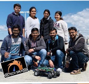
File:CMPE243 Tech Savy Car.jpg Tech_Savy front view |
Abstract
In this project our main aim to build a Self-Navigating Car named Tech Savy, that navigates from a source location to a selected destination by avoiding obstacles in its path using sensors and motors.
Introduction & Objectives
The key features support by the system are
1. A Google-map based Android application is developed which finds out the shortest distance path between current location and destination and connects to the self-driving RC car via Bluetooth to send the GPS Coordinates.
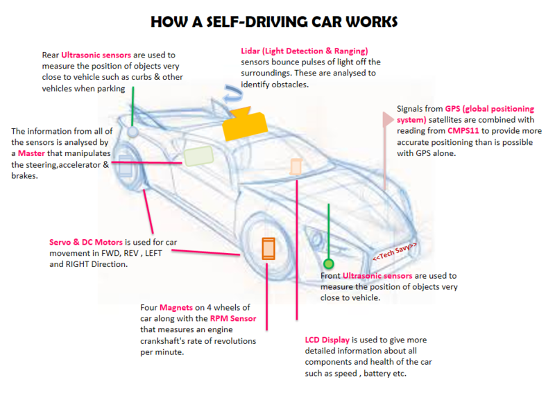
2. The car will be integrated with the GPS, Compass, Bluetooth, multiple sensors such as Ultrasonic sensors and RPM sensors to fulfill the purpose of navigation, obstacle detection, and avoidance
3. LIDAR used for obstacle recognition and avoidance.
4. Motor drives the car by Route Calculation and Maneuvering to the selected destination and Self- Adjusting the speed of the car on Ramp.
5. LEDs and LED Display are used for debugging and to get all relevant information about the status of the car, in real time and LCD Display is used to give more detailed information related to the car.
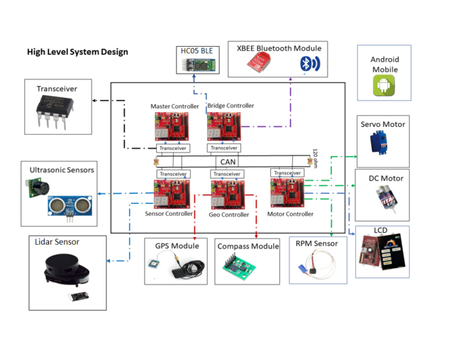
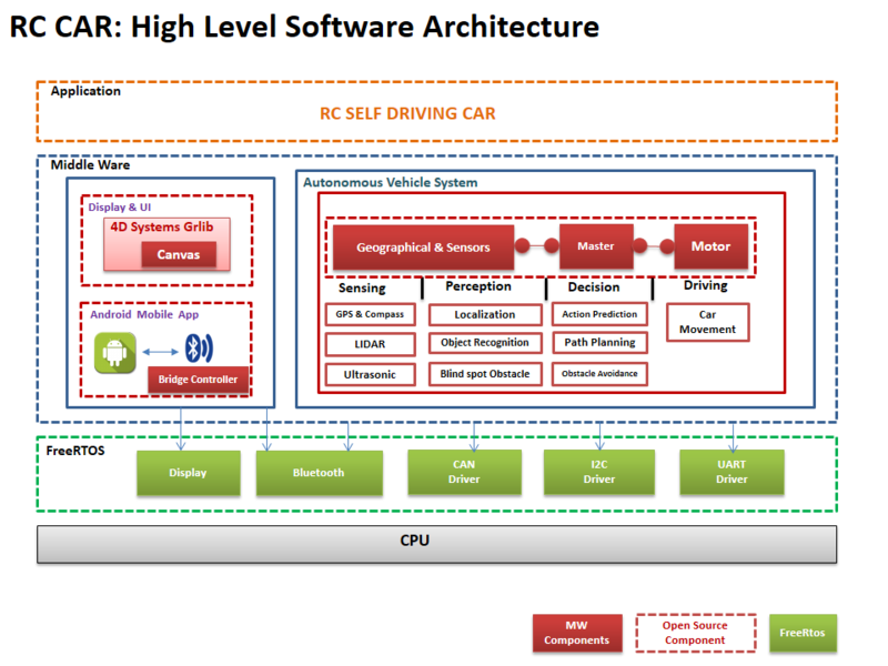
The system is built on FreeRTOS running on LPC1758 SJOne controller and Android application. The main building blocks of Tech Savy are the five controllers communicating through High Speed CAN network designed to handle dedicated tasks. The controllers integrate various sensors that are used for navigation of the car.
CAR Objectives
     1. Master Controller - Handles the Route Manuevering,Path Planning and Obstacle Avoidance
     2. Sensor Controller - Detects the surrounding objects
     3. Geo Controller - Provides current location in the form of coordinates and navigate car using CMPS11
     4. Motor Controller - controls the movement of the Car.
     5. Bridge controller - Interfaces the system using Bluetooth to an Android application.
Team Objectives
     1. Learn each and every module as much as possible, in order to develop an industrial product.
     2. Achieve 100% code coverage, during unit testing.
     3. Document and track all the bugs encountered during development, unit testing, and field testing.
File:CmpE243 TechSavy Application.png Android Application |
Team Members & Technical Responsibilities
- Git Project Link: Tech Savy
- Master Controller
- Motor Controller
- Geographical Controller
- Sensor Controller
- Communication Bridge Controller
- Android Application
- LCD Interfacing & UI Designing
- Hardware PCB Integration
Administrative Responsibilities
| Administrative Roles | ||||
|---|---|---|---|---|
|
Aakash Chitroda | |||
|
Halak Vyas | |||
|
Vatsal Makani | |||
|
Vidushi Jain | |||
|
Jay Parsana | |||
Team Deliverables Schedule
Show a simple table or figures that show you're scheduled as planned before you started working on the project. Then in another table column, write down the actual schedule so that readers can see the planned vs. actual goals. The point of the schedule is for readers to assess how to pace themselves if they are doing a similar project.
| WEEK |
START DATE |
END DATE |
TASK DETAILS |
STATUS |
|---|---|---|---|---|
| 1 | 26 Feb 2019 | 4 March 2019 |
|
Completed Completed Completed Completed |
| 2 | 05 March 2019 | 12 March 2019 |
|
Completed Completed Completed |
| 3 | 13 March 2019 | 19 March 2019 |
|
Completed Completed Completed Completed Completed Completed |
| 4 | 20 March 2019 | 26 March 2019 |
|
Completed Completed Completed Completed Completed Completed |
| 5 | 27 March 2019 | 08 April 2019 |
|
In Progress |
| 6 | ||||
| 7 | ||||
| 8 |
BILL OF MATERIALS (GENERAL PARTS)
| PART NAME |
PART MODEL & SOURCE |
QUANTITY |
COST PER UNIT (USD) |
|---|---|---|---|
|
|
|
|
|
|
| |
|
|
| |
|
|
| |
|
|
| |
|
|
| |
|
|
| |
|
|
| |
|
|
| |
|
|
| |
|
|
| |
|
|
| |
|
|
| |
|
|
|
Printed Circuit Board
<Picture and information, including links to your PCB>
CAN Communication
<Talk about your message IDs or communication strategy, such as periodic transmission, MIA management etc.>
Hardware Design
<Show your CAN bus hardware design>
DBC File
<Gitlab link to your DBC file> <You can optionally use an inline image>
Sensor ECU
<Picture and link to Gitlab>
Hardware Design
Software Design
<List the code modules that are being called periodically.>
Technical Challenges
<Bullet or Headings of a module>
Unreliable sonor sensors
<Problem Summary> <Problem Resolution>
Motor ECU
<Picture and link to Gitlab>
Hardware Design
Software Design
<List the code modules that are being called periodically.>
Technical Challenges
<Bullet or Headings of a module>
Unreliable Servo Motors
<Problem Summary> <Problem Resolution>
Geographical Controller
<Picture and link to Gitlab>
Hardware Design
Software Design
<List the code modules that are being called periodically.>
Technical Challenges
<Bullet or Headings of a module>
Unreliable GPS lock
<Problem Summary> <Problem Resolution>
Communication Bridge Controller & LCD
<Picture and link to Gitlab>
Hardware Design
Software Design
<List the code modules that are being called periodically.>
Technical Challenges
<Bullet or Headings of a module>
Insane Bug
<Problem Summary> <Problem Resolution>
Master Module
<Picture and link to Gitlab>
Hardware Design
Software Design
<List the code modules that are being called periodically.>
Technical Challenges
<Bullet or Headings of a module>
Improper Unit Testing
<Problem Summary> <Problem Resolution>
Mobile Application
<Picture and link to Gitlab>
Hardware Design
Software Design
<List the code modules that are being called periodically.>
Technical Challenges
<Bullet or Headings of a module>
Wifi Link Reliability
<Problem Summary> <Problem Resolution>
Design & Implementation
The design section can go over your hardware and software design. Organize this section using sub-sections that go over your design and implementation.
Hardware Design
Discuss your hardware design here. Show detailed schematics and the interface here.
Hardware Interface
In this section, you can describe how your hardware communicates, such as which BUSes used. You can discuss your driver implementation here, such that the Software Design section is isolated to talk about high-level workings rather than the inner working of your project.
Software Design
Show your software design. For example, if you are designing an MP3 Player, show the tasks that you are using, and what they are doing at a high level. Do not show the details of the code. For example, do not show the exact code, but you may show pseudocode and fragments of code. Keep in mind that you are showing the DESIGN of your software, not the inner workings of it.
Testing & Technical Challenges
Describe the challenges of your project. What advise would you give yourself or someone else if your project can is started from scratch again? Make a smooth transition to the testing section and described what it took to test your project.
Include sub-sections that list out a problem and solution, such as:
<Bug/issue name>
Discuss the issue and resolution.
Conclusion
<Organized summary of the project>
<What did you learn?>
Project Video
Project Source Code
- Git Project Link: Tech Savy
Advise for Future Students
<Bullet points and discussion>
Acknowledgement
References
References
Acknowledgement
Any acknowledgement that you may wish to provide can be included here.
References Used
List any references used in project.
Appendix
You can list the references you used.
Grading Criteria
- How well is Software & Hardware Design described?
- How well can this report be used to reproduce this project?
- Code Quality
- Overall Report Quality:
- Software Block Diagrams
- Hardware Block Diagrams
- Schematic Quality
- Quality of technical challenges and solutions adopted.
