F13: POV Display
Contents
Grading Criteria
- How well is Software & Hardware Design described?
- How well can this report be used to reproduce this project?
- Code Quality
- Overall Report Quality:
- Software Block Diagrams
- Hardware Block Diagrams
- Schematic Quality
- Quality of technical challenges and solutions adopted.
Web-Enabled Persistence of Vision Display
Abstract
The purpose of the project is to build a Persistence of Vision (POV) device that is controlled by the SJSU One board. The POV device will display a message that is input by a remote user via a website setup for this project. The message will be received by the microcontroller using a Wifly RN-XV module integrated onto the SJSU board. The microcontroller will interpret the message and drive the LEDs via an SPI interface to display the message on the POV device.
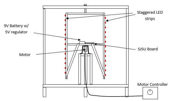
Figure 1 shows the overall system diagram:
Objectives & Introduction
The objective of this project is to learn how to use the SJSU One board and to control external devices using the interfaces provided on the board. Two types of interfaces will be used. The microcontroller will communicate with the Wifly RN-XV module via a UART interface. Then the LEDs will be controlled using an SPI interface. The LEDs will be mounted onto the mechanical POV device and the microcontroller will drive the LEDs to produce the message. A website will be setup to provide a user interface to control the device.
The team will be divided into two groups. Team 1 will be responsible for the web interface and integration of the Wifly module on the SJSU board to communicate with the website. Team 2 will build the POV device and write the driver to display the user message on the POV display. A summary of the team and responsibilities is shown below:
Team Members & Responsibilities
Team 1 (Jorge Del Valle and Matt Heffner)
- Website Development
- Wifly module setup
- Front end communication from website to microcontroller via the Wifly RN-XV module
Team 2 (Jasko Begovic and Thu Hoang)
- Construction of the Mechanical POV device
- LED driver software
Both teams will participate in the integration and testing of the project.
The project will take 6 weeks to complete. The following table shows weekly project milestones and the team's progress.
| Date Planned | Milestone | Status |
| 22-Oct | Wifly part received; POV parts ordered and shipped | Complete |
| 29-Oct | Integrate Wifly to SJSU board and connect to Wifi connection | Complete |
| 5-Nov | Finish mechanical assembly & any electrical interfaces (Hall effect switch.) Read datasheets, obtain necessary libraries for LED device, understand & modify libraries to work with SJSU board Setup Website for user interface to the device | Complete |
| 12-Nov | Implement code to receive data from website via the Wifly module | Complete |
| 19-Nov | Finish code for LED driver. Display the alphabet. Start integration of the Wifly portion with the POV device | Complete |
| 26-Nov | Project testing. Have working Assembled code with Web-half & test by inputing various strings via the website | Complete |
| 3-Dec | Present demonstration and submission of project report | Complete |
| 7-Dec | Present demonstration and submission of project report | Complete |
Parts List & Cost
| Part | Cost |
| Wifly RX-NV module | $35 |
| Web Hosting through iPage | $12 |
Design & Implementation
The design section can go over your hardware and software design. Organize this section using sub-sections that go over your design and implementation.
The user interface for the project will be http://povdisplay.com. The user will input a message to be displayed on the POV device, as well as, the RGB color to use.
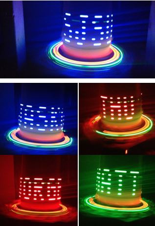
Several preliminary photos and videos can be found at: http://povdisplay.com/project-videos.html
Hardware Design
Discuss your hardware design here. Show detailed schematics, and the interface here.
Mechanical Requirements
The POV display requirements were necessarily derived from the dimensions of the LED strip and the dot matrix font that was chosen. The strips chosen are Adafruit LPD8806 RGB strips, primarily because of their high refresh rate at 4000 Hz. The font chosen is reproduced below in Figure 2 for discussion.
Figure 2: Dot Matrix Font for the POV display
In order to display a single character, the display’s width should be a minimum of 5 pixels wide. Using the LED strip’s dimensions as a starting point, the RGB pixels are 5050, meaning half a centimeter wide by half a centimeter tall, and are spaced 31 mm apart. If the strip’s pixel spacing is maintained, then the display should be 6” wide as a minimum so that the viewer can see 5 pixels across. If instead two strips of LEDs are used, with the strips staggered vertically so that the LED spacing is halved, then only a 3” minimum diameter is needed.
Figure 3: Diagram of LED strips
Initially, a personal blower was thought to be sufficient to provide the framework on which to build the POV display. The rotating cylinder of blower has dimensions of 3” diameter x 5” tall. This is sufficiently wide to display a single character; however, with the manageable sized cylinder came the small sized motor. Since this motor was not intended to move anything but air, it is not expected to have enough torque to move the combined weight of the board, LED strips, wires, and battery pack. A motor with a higher torque is needed.
In addition to the higher torque, the motor needs to have sufficient speed. POV displays work on the principle that an afterimage persists on the retina of the human eye for approximately 40 ms (1/25th of a second). Therefore the motor must be able to spin a pixel a complete revolution in 40 ms or 25 Hz. 25 cycles per second translates to 1500 rpm minimum.
Suppose now that the display is 12.6” or 32 cm in diameter. If no horizontal spacing between the pixels are allowed, then that translates to pi*32 /0.5 = 201 pixels around the circumference. The entire circumference must be refreshed in 40 ms to maintain persistence of vision. When using a single strip, the LED must transition from one column to the next in 40ms/201 ~ 0.2 ms. Therefore the minimum refresh rate needed for a display of this size is 1 / 0.2 ms = 5 kHz, slightly higher than the refresh rate possible with the LPD8806. Therefore, some horizontal spacing between the pixels is required for a display of this size. If a spacing of 1 pixel is used, then the refresh rate can be halved to 2.5 kHz.
A display rotating at 1500 rpm that requires a high torque, high speed motor must be precisely machined to operate safely. Since this is not possible within the self-imposed budget constraints of the project, we chose the best possible speed that can operate safely with manually crated components. This motor is the 12V, 500 rpm motor from BatterySpace.com.
Figure 4 depicts the POV display that was manually crafted for this project.
Figure 4: Mechanical Diagram of POV display
Hardware Interface
In this section, you can describe how your hardware communicates, such as which BUSes used. You can discuss your driver implementation here, such that the Software Design section is isolated to talk about high level workings rather than inner working of your project.
Software Design
Show your software design. For example, if you are designing an MP3 Player, show the tasks that you are using, and what they are doing at a high level. Do not show the details of the code. For example, do not show exact code, but you may show psuedocode and fragments of code. Keep in mind that you are showing DESIGN of your software, not the inner workings of it.
Implementation
This section includes implementation, but again, not the details, just the high level. For example, you can list the steps it takes to communicate over a sensor, or the steps needed to write a page of memory onto SPI Flash. You can include sub-sections for each of your component implementation.
Testing & Technical Challenges
Describe the challenges of your project. What advise would you give yourself or someone else if your project can be started from scratch again? Make a smooth transition to testing section and described what it took to test your project.
Include sub-sections that list out a problem and solution, such as:
Wifi Connection Issues
Many wifi connection issues were encountered. To solve this problem, a dedicated task was created to re-connect to wifi if the connection was ever lost.
Conclusion
Conclude your project here. You can recap your testing and problems. You should address the "so what" part here to indicate what you ultimately learnt from this project. How has this project increased your knowledge?
Project Video
Project Video
Project Source Code
Send me your zipped source code and I will upload this to SourceForge and link it for you.
References
Acknowledgement
Any acknowledgement that you may wish to provide can be included here.
References Used
List any references used in project.
Appendix
You can list the references you used.


