F17: Tata Nano
Contents
Grading Criteria
- How well is Software & Hardware Design described?
- How well can this report be used to reproduce this project?
- Code Quality
- Overall Report Quality:
- Software Block Diagrams
- Hardware Block Diagrams
- Schematic Quality
- Quality of technical challenges and solutions adopted.
PAGE UNDER CONSTRUCTION
Tata Nano
Self-Navigation Vehicle Project
Abstract
Embedded system is a collection of hardware and software that are designed for a specific function that is a part of a larger system. Self driving car provides a challenge and opportunity to design a unique system that will solve a problem of getting from point A to point B. This project is focus on the industry standard and will go through a complete product lifecycle using the practice knowledge acquired in classroom with scrum methodology practiced by the team.
Key components of this self driving car are:
- Android App interface with car
- Obstacle detection and avoidance
- Auto speed adjustment
- GPS Navigation
Objectives & Introduction
Show list of your objectives. This section includes the high-level details of your project. You can write about the various sensors or peripherals you used to get your project completed.
The self-driving car is considered a capstone of technical achievement for an embedded system. This project gives a very basic and essential experience in working with the core requirements for a working self-driving car. The project is subdivided into 5 modules:
- Master Module - Mater Module is the center of all communication, it receives all the data from different modules and takes decisive action according to the data.
- Sensor Module - Sensor Module is responsible for obstacle detection and updating the master controller with the distance values of the obstacle.
- Motor Module - Motor Module is responsible for the driving and steering action of the car.
- Geo Module - Geo Module is responsible for updating the Motor Controller about the direction motion.
- Bridge Module - The android and communication bridge controller are responsible for establishing communication between the car and take Map checkpoints for the shortest route to the destination that the car must take.
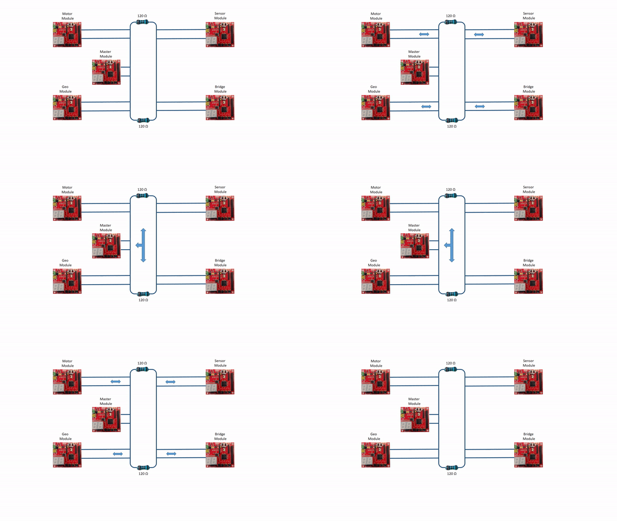
CAN bus will be used as a communication bus between microcontrollers. Can Bus is a broadcast bus where all the controller will be listening to the incoming frames, CAN bus uses frames for data communication. Each module will have its unique ID called MsgID, the system startup is initiated with a START command sent to car from Android application. The path and destination are configured prior to START command. The car will navigate between the checkpoints by taking location feedback through a GPS system and using sensors for obstacles avoidance in the path of the car. IO systems present on the car give us information about the status of the car.
The Objectives of this project are:
- All the modules must communicate with each other over the CAN bus.
- The car must determine and avoid obstacles using LIDAR and ultrasonic sensors.
- The car must interact with a Bluetooth mobile application, obtaining checkpoint and path data.
- Car must be able to speed control based on the terrain.
- The car must be able to gather location using GPS module and route towards the destination.
- Provide module and sensor status using the LCD or LEDs.
- Master must be able to determine the action required by data gathered through sensors and GPS.
Team Members & Responsibilities
- Master Controller
- Manan Mehta
- Shivam Chauhan
- Geographical Controller
- Kalki Kapoor
- Aditya Deshmukh
- Communication Bridge + Android Application + LCD
- Ashish Lele
- Venkat Raja
- Motor and I/O Controller
- Aditya Choudari
- Shashank Iyer
- Sensor Controller
- Pushpender Singh
- Hugo Quiroz
- Module Level Testing
- Manan Mehta
- Shashank Iyer
Project Schedule
Legend: Motor & I/O Controller , Master Controller , Communication Bridge Controller, Geographical Controller, Sensor Controller , Team Goal
| Week# | Start Date | End Date | Task | Status |
|---|---|---|---|---|
| 1 | 09/12/2017 | 09/19/2017 |
|
Completed |
| 2 | 09/19/2017 | 09/26/2017 |
|
Completed |
| 3 | 09/26/2017 | 10/03/2017 |
|
Completed |
| 4 | 10/03/2017 | 10/10/2017 |
|
Completed |
| 5 | 10/10/2017 | 10/17/2017 |
|
Completed |
| 6 | 10/17/2017 | 10/24/2017 |
|
Completed |
| 7 | 10/24/2017 | 10/31/2017 |
|
Completed |
| 8 | 10/30/2017 | 11/7/2017 |
|
Completed |
| 9 | 11/7/2017 | 11/14/2017 |
|
Completed |
| 10 | 11/14/2017 | 11/21/2017 |
|
Completed |
| 11 | 11/21/2017 | 11/28/2017 |
|
In-Progress |
| 12 | 11/28/2017 | 12/05/2017 |
|
|
| 13 | 12/05/2017 | 12/12/2017 |
|
- |
Parts List & Cost
| Item# | Part Desciption | Vendor | Qty | Cost |
|---|---|---|---|---|
| 1 | RC Car - Traxxas 1/10 Slash 2WD | Amazon | 1 | $189.95 |
| 2 | Traxxas 2872X 5000mAh 11.1V 3S 25C LiPo Battery | Amazon | 1 | $56.99 |
| 3 | Traxxas 7600mAh 7.4V 2-Cell 25C LiPo Battery | Amazon | 1 | $70.99 |
| 4 | Traxxas 2970 EZ-Peak Plus 4-Amp NiMH/LiPo Fast Charger | Amazon | 1 | $35.99 |
| 5 | Bluetooth Module HC-05 | Amazon | 1 | $8.99 |
| 6 | 4D systems 32u LCD | 4D systems | 1 | $73.70 |
| 7 | LV Maxsonar EZ0 Ultrasonic sensors | Robotshop | 5 | $124.75 |
| 8 | LIDAR Sensor | Robotshop | 1 | $190 |
| 9 | Ultimate GPS breakout | Adafruit | 1 | $49.95 |
| 10 | CAN tranceivers | Microchip Samples | 10 | Free |
| 11 | SJOne Boards | Provided by Preet | 5 | $400.0 |
DBC File Link
https://gitlab.com/shivam5594/Autonomous-car/blob/embedded/common_dbc/243.dbc
Design & Implementation
The design section can go over your hardware and software design. Organize this section using sub-sections that go over your design and implementation.
Hardware Design
Discuss your hardware design here. Show detailed schematics, and the interface here.
Hardware Interface
In this section, you can describe how your hardware communicates, such as which BUSes used. You can discuss your driver implementation here, such that the Software Design section is isolated to talk about high-level workings rather than the inner working of your project.
Lidar Sensor
Lidar Sensor is interfaced using a UART Protocol. As shown below the Lidar Sensor sends 5 bytes per data point over UART to the Sensor Controller. These 5 bytes include 1 byte for the quality of data, 2 bytes for the angle of reading, and 2 bytes for the distance of reading. The Sensor Board initiates the Lidar Sensor readings by sending a start command opcode. The Lidar Sensor responds by sending a start scan confirmation followed by continuous data readings.
Ultrasonic Sensor
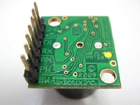
LV‑MaxSonar‑EZ1 ultrasonic sensor by MaxBotix is used for a wide range object detection. Ultrasound sensors are configured as 2 ultrasound sensors in the front and one in the rear, this configuration helps to work in conjuncture with Lidar sensor mounted on the center of the car. LV‑MaxSonar‑EZ1 can detect objects from 0 inches to 254 inches, the object detected within 0-6 inches are provided with range information of 6 inches and the resolution is 1 inch. LV‑MaxSonar‑EZ1 provides three output formats pulse width output, analog output, and RS232 serial output. This project is using pulse width as the output from ultrasound sensors.
The following figure shows the pinout of the LV‑MaxSonar‑EZ1 ultrasonic sensor.
Pin Out description
Pin 1-BW- When BW pin is held high the TX output sends a pulse suitable for low noise chaining.(Not Used)
Pin 2-PW- This pin outputs a pulse width representation of range. The distance can be calculated using the scale factor of 147uS per inch.
Pin 3-AN- Outputs analog voltage with a scaling factor of (Vcc/512) per inch.(Not Used).
Pin 4-RX– This pin is internally pulled high. The LV-MaxSonar-EZ will continually measure range and output if RXdata is left unconnected or held high. If held low the sensor will stop ranging. Bring high for 20uS or more to command a range reading.
Pin 5-TX- When the *BW is open or held low, the TX output delivers asynchronous serial with an RS232 format.(Not Used)
Pin 6-+5V- Vcc – Operates on 2.5V - 5.5V. Recommended current capability of 3mA for 5V, and 2mA for 3V. Please reference page 4 for minimum operating voltage versus temperature information. Pin 7-GND- Return for the DC power supply.
GND- must be ripple and noise free for best operation.
uLCD32-PTU
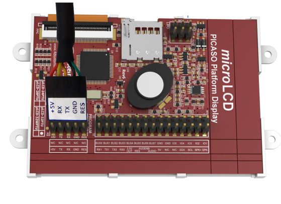
uLCD32-PTU by 4D systems has a 3.2" TFT LCD Display module. The module comes with a display resolution of 240x320 pixels. 4D Systems provides a programming cable based on UART for burning the LCD code to the module. The project is burnt to a uSD card which is used for display during booting of the LCD.
The following figure shows the programming cable and the pins of uLCD32-PTU.
Software Design
Show your software design. For example, if you are designing an MP3 Player, show the tasks that you are using, and what they are doing at a high level. Do not show the details of the code. For example, do not show exact code, but you may show psuedocode and fragments of code. Keep in mind that you are showing DESIGN of your software, not the inner workings of it.
Implementation
This section includes implementation, but again, not the details, just the high level. For example, you can list the steps it takes to communicate over a sensor, or the steps needed to write a page of memory onto SPI Flash. You can include sub-sections for each of your component implementation.
LCD DISPLAY
uLCD-32PTU communicates with the SJ1 board over UART. The steps taken for interfacing the LCD display with the SJ1 board are listed below:
- Creating a project using Workshop 4 IDE and programming the LCD display
- After finalizing the design of the LCD's layout, a genie project was created using Workshop 4.
- The layout was split into different forms (pages) and appropriate buttons and gauges were added for display.
- uLCD-32PTU was programmed with the help of programming cable provided by 4D systems.
- Programming SJ1 Board for LCD Display
- As raw data often cannot be displayed on the LCD directly, the values to be displayed had to be converted to appropriate byte-sized values.
- Communication with SJ1 board was established at the baud rate of 115200 bps.
- Commands for writing data and reading acknowledgment for various gauges were coded in the SJ1 board.
Testing & Technical Challenges
Describe the challenges of your project. What advise would you give yourself or someone else if your project can be started from scratch again? Make a smooth transition to testing section and described what it took to test your project.
Include sub-sections that list out a problem and solution, such as:
LCD
- Problem: The SJ1 Board was rebooting frequently while sending data for all metrics at once.
- Resolution: The metrics were split into different forms for display and the data belonging to the active form alone was sent.
Conclusion
Conclude your project here. You can recap your testing and problems. You should address the "so what" part here to indicate what you ultimately learnt from this project. How has this project increased your knowledge?
Project Video
Upload a video of your project and post the link here.
Project Source Code
References
Acknowledgement
Any acknowledgement that you may wish to provide can be included here.
References Used
- uLCD 32 PTU datasheet http://www.4dsystems.com.au/productpages/uLCD-32PTU/downloads/uLCD-32PTU_datasheet_R_2_1.pdf
- Workshop 4 user guide http://www.4dsystems.com.au/productpages/4D-Workshop-4-IDE/downloads/Workshop-4_userguide_R_2_1.pdf
Appendix
You can list the references you used.


