S17: Smart security system
Contents
Smart security system
Abstract
The fact that we are often not home doesn’t have to mean our home can’t be safe. That’s why we decided to work on smart security system which will provide safety and piece of mind for users.
Main task of our project is to detect movement, turn camera towards critical area, take a picture and upload it to web where user will be able to see what was captured. Also, user will be given a possibility to control camera remotely.
It is all done by using two SJOne boards. One of them is used as remote control while the other one will be our brain which will control everything. Two motion sensors are connected to main SJOne board. If they sense the movement, controlor will send PWM signal to move motors in desired direction. Controlor will, at the same time, send signal over UART to Raspberry Pi which controls the camera and take a picture. Picture is then sent as .jpeg to web. It is received by our web application and displayed to screen where user can see what was captured. Based on what he sees user can use remote control (SJOne board) and move camera left, right, up or down.
We are taking accelerometer values from SJOne board which is used as remote control and sending them over Nordic Wireless to other board. After other board receives those values it will send PWM signal to move motors/camera in desired direction.
Objectives & Introduction
Introduction
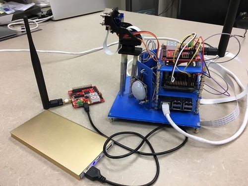
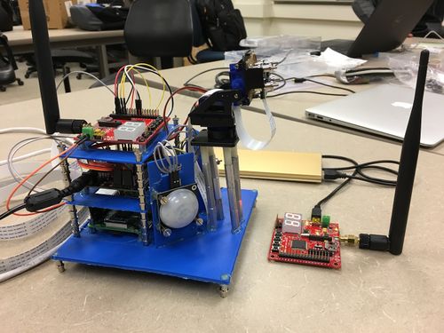
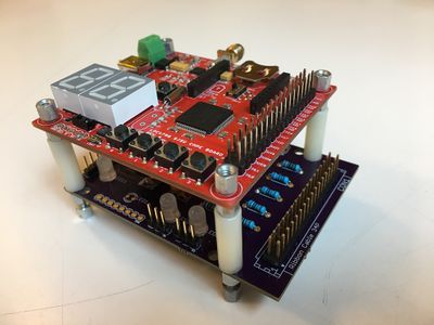
As it can be seen on photos above we utilized two SJOne boards, custom made PCB and Raspberry Pi in our project. Two PIR sensors connected to PCB are detecting movement and sending signals to main controller, SJOne board. Two motors which control camera are also connected to PCB, but controlled from SJOne board. GPIO ports are used to collect values from the sensors and PWM signal is sent to motors in order to control them. Raspberry Pi is used to interface the camera, but camera itself is controlled by sending capture signal over UART from SJOne board to Raspberry Pi.
In order to have all nicely packed we did 3D printing (blue color parts). All three boards PCB, Raspberry Pi and SJOne board are stacked up and each sensors is placed on custom made printed part, with holes for cables. This provides possibility for whole design to be mobile and to be placed anywhere acting as independent mobile surveillance unit.
Objectives
The objectives are as follows:
- To be able to detect the movement by using PIR sensors and send signals to SJOne board
- To be able to move motors which holds camera mount left, right, up and down by PWM signal
- To be able to send signal over UART from SJOne board to Raspberry Pi
- To be able to take a picture and upload it to web
- To be able to receive and show picture on the web
- To be able to take accelerometer values from one SJOne board and send it over Nordic Wireless to another
Team Members & Responsibilities
- Sensor, Servo motors, Nordic wireless
- Camera Interface & 3d Printing Designs
- Web UI design and uploading image to web
- PCB, Accelerometer
- PCB
Project Schedule
| Sr. No. | Start Date | End Date | Task | Status | Actual Completion Date | |
|---|---|---|---|---|---|---|
| 1 | 03/20/2017 | 03/26/2017 |
|
Completed | 03/26/2017 | |
| 2 | 03/27/2017 | 04/02/2017 |
|
Completed | 05/21/2017 | |
| 3 | 04/03/2017 | 04/09/2017 |
|
Completed | 04/09/2017 | |
| 4 | 04/10/2017 | 04/16/2017 |
|
Completed | 04/20/2017 | |
| 5 | 04/17/2017 | 04/27/2017 |
|
Completed | 04/30/2017 | |
| 6 | 04/28/2017 | 05/04/2017 |
|
Completed | 05/04/2017 | |
| 7 | 05/05/2017 | 05/18/2017 |
|
completed | 05/21/2017 | |
| 8 | 05/19/2017 | 05/23/2017 |
|
completed | 05/24/2017 |
Parts List & Cost
| Item. No. | Part Description | Vendor | Qty | Cost |
|---|---|---|---|---|
| 1 | SG90 Micro Servo motors | ebay | 4 | $26 |
| 2 | Wireless antenna | Amazon | 1 | $8 |
| 3 | RF male to male antenna connector | Anchor electronics | 1 | $10 |
| 4 | Motion sensors | Fry's electronics | 2 | $24 |
| 5 | Camera mount | ebay | 1 | $1.79 |
| 6 | Raspberry Pi | Amazon | 1 | $35 |
| 7 | Camera | Amazon | 1 | $25 |
| 8 | Voltage Regulator LM7805 | Amazon | 2 | $3 |
| 9 | Resistors 1K | Fry's Electronics | 9 | $2 |
| 10 | Capacitors 0.1uF | Fry's Electronics | 2 | $2 |
| 11 | Capacitors 0.33uF | Fry's Electronics | 2 | $2 |
| 12 | LED | Fry's Electronics | 9 | $2 |
Design & Implementation
Hardware Design
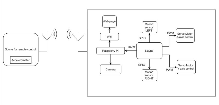
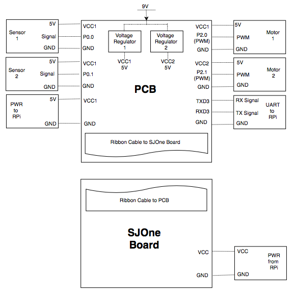
The below figure shows the high level hardware design of our project.
PIR Motion Sensor
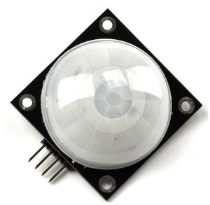
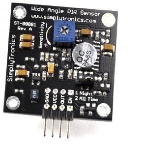
The ST-00081 is a PIR Sensor that detects motion by sensing the change in the infrared levels of the nearby objects. Whenever any motion is detected the sensor will make the output pin high. The ST-00081 is capable to detect any motion with angle as large as 180˚.We have a potentiometer (Blue part in the back view for PIR sensor) to adjust the sensitivity for the sensor. We are using two PIR sensor to trigger the Camera and take a picture if any object is detected. We are using two PIR sensor to give the orientation for the camera depending where the motion is detected. The sensors will detect any motion (either left or right) depending which sensor detects the moving object. If both sensors detect motion at the same time, it means there is heavy motion of both sides and the camera will be facing the center(the path between two sensors) .
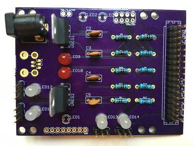
PCB Design
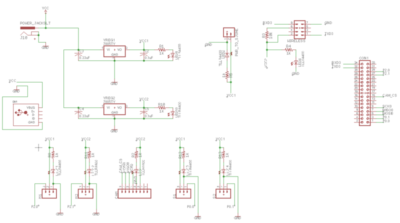
PCB design was created in Autodesk Eagle v8.1.0. But first we created a draft, on paper, with all parts and functionalities we wanted to put on our PCB. On sparkfun.com there is a great tutorial about how to create schematic in Eagle.
First decision we had to make was what parts to use. Since we didn’t know fab companies are not soldering components, or charge extra for that, we created schematic with surface-mount components. After realising how small surface-mount components are and how difficult will be to solder them we had to start all over and change all components to through-hole.
Another important step was to choose library from which components will be imported. There is many library out there but we used sparkfun, adafruit and default Eagle library.
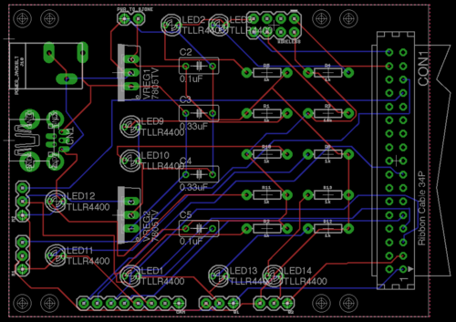
We created a Board/Board Layout From Schematic also by following sparkfun tutorial Using EAGLE: Board Layout. One of the things that wasn’t well explained in this tutorial is how to create board with your specific dimensions. SInce our plan was to mount SJOne board above PCB it was important to make PCB with the same dimensions as SJOne board and more important, to have holes for standoffs at the same place as the one on SJOne board. Luckily there is “Dimension” tool we used for that, although it wasn’t so easy to delete the lines that are left after using that tool.
After placing components where we wanted them, routing the board was easy with Autorouter...NOT. It produced too many errors, and wires were going too close to through-holes so we have to move wires away from them and basically do the routing manualy. Advice about routing would be to try to keep wires away as much as you can from through-holes, because when we were soldering components we were afraid that iron can damage the routes.
Checking for errors was maybe the most important part of whole process since it helped us detect and correct few errors which we didn’t see during layout. In order to check for errors tool “DRC” Design Rule Check is used. First we used sparkfun anddefault Eagle drc files to check for errors but after we decided which fab company to used, and after checking their website and guidelines we also did final check with their drc file, what is strongly recommended. Same goes with CAM file that helped us create gerber files recomended by fab houses.
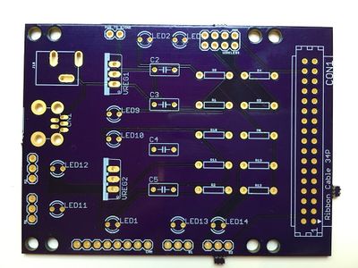
Picking a PCB manufacturer was really easy after reading this analysis. We used Oshpark because of this sentence “The quality is excellent, the boards are produced domestically, and shipping is covered in your board price.” No need to say more….or actually there is...they are purple. Yes you read right, purple. It took less then 10 days to receive them from the day we submitted our request.
We already had many components we needed but the ones we didn’t have we had to buy. As the best choice, regarding the price, there is Excess Solution.
Hardware Interface
As you can see on Detailed Hardware Diagram below we used PCB to collect all “wiring” thus making only one ribbon cable going to our main controler to SJOne board. All pins on PCB corespodents to same pins on SJOne board. Those pins are:
- GPIO pins P0.0 and P0.1 to receive signals from Sensor 1 and Sensor 2
- PWM pins P2.0 and P2.1 to control motors
- UART pins RXD3 and TXD3 to send signal to Paspberry Pi to make camera take a photo
Also notable seeing is that there is 9V input which is scaled down to 5V with two voltage regulators LM7805 which provide power to sensors, motors and Raspberry Pi. Also it was meant to power up camera but since we had problems with interfacing camera to SJOne board (you can read more in “My Issue #1”) we ended up not powering camera from PCB and instead providing power to Raspberry Pi instead.
Software Design
This section describes the software design used for our project. Different software tasks used in the project are explained and the communications between tasks are described in detail. Each task's working is shown in the flowchart under each section.
Accelerometer
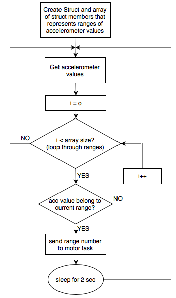
We are taking accelerometer values at SJOne board that is used as remote control and sending numbers that represent range which accelerometer is currently at. There is eight ranges per axis with numbers -4 to 4 representing them. First we created struct with three members, starting value of range, end value of range and number of range. Then we create and initialize array with struct as members. Inside while(1) loop we are getting accelerometer values and looping through all ranges, where we checking if read value of accelerometer belongs to range we are currently at. If the read value belongs to the current range, send the number of that range to motor task.
The below flowchart explains how this tasks works.
Nordic Wireless
In this project we are using two SJOne boards. One of them will be connected to two motors which are turning camera arm in desired direction. Camera direction will be based on two events. One of them is if sensor detect movement camera will turn in direction covered by that sensor and another one is controled by client or user of this system by turning another SJOne board. Another SJOne board will serve as a joystick or remote control and it will be possible to turn camera in desired direction by turning SJOne board. Two boards, the one that serve as remote control and the main one will communicate by utilizing Nordic Wireless.
In order for two nodes, in Nordic Wireless, to be able to communicate they need to have same channel number. It is done by editing sys_config.h file Chanel number can be any number between 2402 and 2500
#define WIRELESS_CHANNEL_NUM 2455 ///< 2402 - 2500 to avoid collisions among 2+ mesh networksBeside that each node need to have unique address which can bee any number between 1 – 254
#define WIRELESS_NODE_ADDR 110 ///< Any value from 1-254We also changed node name, to “tx” and “rx” for testing purpose when we first wanted to ping other board and get its name.
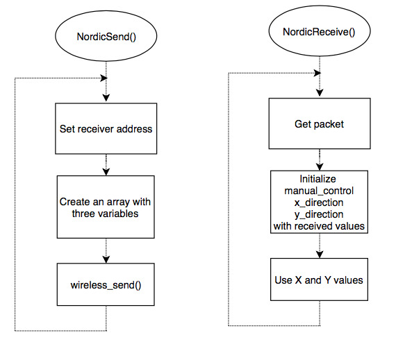
Our NordicSend() task first creates data array with three variables. Two variables are actually X and Y axis values from accelerometer sensor and third indicates this is a manual control, since camera can be turned by sensor too, as explained above. When sending a packet it is important to include address of receiver, “rx” node, number of hops, which in our case can even be 0 since for demo purpose our two boards will be close and will communicate directly with each other, and number of variables. Then it just sends formed packet.
Receiver node, NordicReceive() just receives a packet in defined period of time which gives us three variables sent by “tx” node, representing X and Y axis values, based on which we will control motors and thus turn camera in desired direction and third variable indicating this is a manual control.
The below flowchart explains how this works.
Servo motor
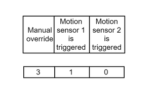
Two SG90 micro servo motors are used to construct the camera mount. The two servos are set up such that the camera can be rotated 180 degrees along both x and y axis. The servo motor task is waken up by event groups of 3 bits - Manual control override, Left Motion sensor and Right Motion sensor. The work flow of the task is shown in the below flowchart.
Camera
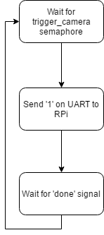
The camera task is a simple task of informing Raspberry Pi to take a picture. Since LPC1768 does not have the RAM capacity to handle images, we use Raspberry Pi to interface camera. Raspberry Pi module is controlled by the SJOne's camera task. This task waits on 'camera_trigger' semaphore given by servo task. Once it takes the semaphore, it sends '1' over UART3 to Raspberry Pi, which in turn takes a picture and uploads to webpage over Wifi. Once the camera is done clicking the picture, the Raspberry Pi sends a 'Done' signal via UART. The camera task holds the CPU until is signal is received since the camera is busy and can not accept another 'camera_trigger'.
Implementation
The software flow was designed such a way that different modules work together, each with a priority assigned and a running rate. The software is divided into different task, each performing a specific task. The overall project involves two boards communicating over wireless network.
On the main SJOne board which is the heart of the security system controls two motion sensors, two servos, camera, wifi and Nordic Receiver. The other board which is used for manual control by the user houses accelerometer, switches for control commands and nordic transmitter.
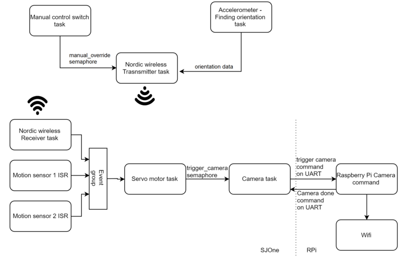
Below figure shows how tasks communicate to each other on a board and across boards.
As can be seen in the figure, most tasks communicate with each other via semaphores. On the transmitter side, when user enables the manual control by pressing SW1, a semaphore is given to Accelerometer task, which calculates the orientation and to the Nordic transmitter task, which transmits the orientation value and control commands over wireless mesh network.
On the Receiver side board, servo motor turns the camera based on the motion sensor values by default(left or right) or based on accelerometer orientation if the manual override is ON. Hence the servo task's response is based on 3 different modules - Motion sensor 1, Motion sensor 2 and Nordic wireless receive(which receives the manual override and accelerometer orientation values). Therefore we use 'Event groups', where the servo task wakes up if any of the three tasks set a bit in the event group. Once the task is awake, it checks the 3 bits to see which event invoke it.
The priority is given to manual override bit. If manual override is set, the motion sensors values are ignored and servo responds to accelerometer orientation received over wireless network. If the manula override is OFF, then servo turns left or right or center based on left sensor is triggered or right sensor is triggered or both sensors are triggered.
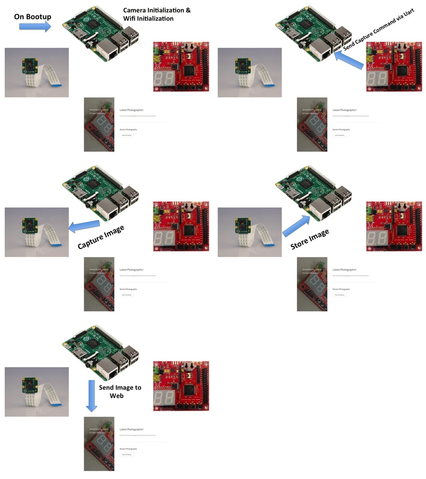
Whenever the motion sensors are triggered, servo orients the camera to the desired position and gives a semaphore to 'camera task'. This semaphore wakes up the camera task, which transmits command '1' over UART to the Raspberry Pi. When the command '1' is received, raspberry Pi triggers the camera to take a picture and invokes wifi task to upload the image to the webpage.
On the Raspberry PI, we have used the new operating system called Android Things. It is developed by Android and its implementation is just like an Android Mobile Application. The drivers for the Android things are already provided by
Android and implemented on Android Things operating Systems. So when Uart receives a data it goes into a function callback. In that callback function we check if the data is the command to capture the image. If that is the case then we trigger the capture image command. Once the image is captured we trigger the upload image method. In the upload image method we send the image via POST request to the web domain. The flow is as follows:
The web domain is hosted on heroku which is a platform as a service (PAAS) application which allows us to host our web code for free. On the web domain, whenever the request comes, it accepts the image saves it on the folder and from the gallery image we can view all the images which are sorted by time. i.e. the latest image is at the top. The website layout is as follows:
Testing & Technical Challenges
My Issue #1
Interfacing camera with SJOne board
Problem: First issue we encountered was when we wanted to interface camera to the SJOne board. If you look at the pictures of PCB you will notice that in bottom part of PCB there is 8 through-holes that were meant to be used for the camera. They are left unused since camera we had was Arducam. It was supposed to be able to interface it with any board using I2C or SPI. It turned out that only way to interface that camera is by using Arduino boards or Raspberry Pi with Arduino library. So don’t try to do that.
Problem: Next we moved on to interface OV7670 image sensor. This sensor required us to provide an external clock or oscillator. Since the PCLK pin is not accessible on SJOne board, we provided clock from another LPC1769 board. While we successfully interfaced this sensor and was able to take a picture, the RAM requrired to store it was very large and no other task can run if camera is interfaced.
Solution: Problem was solved after consulting Preet and getting permission to use Raspberry Pi just to interface camera. However we control Raspberry Pi from SJOne board by transmitting control signal via UART.
My Issue #2
Male/Female connector for wireless antennas
Problem: We had an issue with antennas for Nordic Wireless. Before we ordered antennas we contacted colleague who was using antennas on SJOne board two semesters before us. With his reference we ordered same antennas, since they've been using them successfully. When antennas arrived our code was already written and ready to test. We were really looking forward to this since this was one of interesting parts of our project. The problem was that antennas we ordered had female connector same as our SJOne boards. SJOne boards manufactured a year ago had male connector so they could use this antennas.
Solution: We didn't want to order new antennas and spend additional money, so we borrowed older SJOne boards just to test our board. Another solution is to buy male to male connectors to interface SJOne to female antennas.
Conclusion
Conclude your project here. You can recap your testing and problems. You should address the "so what" part here to indicate what you ultimately learnt from this project. How has this project increased your knowledge?
Project Video
Project Source Code
Future improvements
It would be great to see some improvements to our design and functionalities. We had many ideas but not time to realized them all. Adding more cameras and sensors will make both hardware and software design more complex but adding new functionalities is what we want to see in the future.
Solar panels prices nowadays are going down so combining our design with them would make whole system possible to be used outside as power independent mobile surveillance system. Obtaining reliable power for remote site security can become a problem. Going even further, combine RC car, solar power and our design in one project will make the ultimate, mobile theft protection system.
References
Acknowledgement
We would like to thank Prof. Preetpal Kang for Realtime OS on Embedded Systems course at SJSU and the continued guidance he provided through out the semester. The course content and his practical teaching helped with the design, implementation and testing of our project. We also appreciate our Student Assistants(ISAs) for their guidance. This project helped us gain the knowledge on various aspects of practical Real time embedded system and also helped us hone our skills. This course and the project will be an asset to our career.
References Used
[1] CMPE 244 Lecture notes from Preetpal Kang, Computer Engineering, San Jose State University. Jan-May 2017.
[2] FreeRTOS documentations
[3] SG90 micro servo datasheet
[4] Parallex wide angle motion sensor datasheet
[5] FreeRTOS API reference
[6] Spring'16 and Spring'15 project reports
