S17: Halo
Contents
- 1 Abstract
- 2 Objectives & Introduction
- 3 Schedule
- 4 Parts List & Cost
- 5 Design & Implementation
- 6 Testing & Technical Challenges
- 7 Conclusion
- 8 References
Abstract
This project aims to improve the safety of bicyclists on busy roads. According to the National Highway Traffic Safety Administration, Traffic Safety Facts, 818 people lost their lives in bicycle/motor vehicle crashes in 2015. This represents a 6 percent increase in bicyclist fatalities since 2006 and a 12.2 percent increase from the previous year (2014). Often, it is difficult for drivers in cars to judge the movement of a bicyclist on road. This problem escalates in scenarios when the driver has to follow a bicyclist in dark environments. We introduce "Halo", a smart helmet which makes bicyclists feel safe and stand out on busy roads, thus improving their safety.
Objectives & Introduction
We propose to build a simple yet, powerful system that helps improve the safety of bicyclists on busy roads. The system has been designed to have the following modules:
- Motion Analysis Engine (MAE)
- Accelerometers are used to detect the state of the motion and show caution signals on the helmet when the bicyclist slows down or comes to a stop in traffic.
- UltraSonic Sensor Module (USS)
- Ultrasound sensors are used to detect if there is any vehicle following the bicyclist in close range. If the bicyclist is slowing down traffic and making the vehicle behind to follow closely, a buzzer is turned off to indicate the bicyclist to give way. This helps the cyclist to be safe from rash drivers as well as be alert if they are unknowingly slowing traffic.
- Indicator switches to indicate lane changes and turns (User Input Output)
- DPDT switches are used as indicators which trigger turn signals on the helmet of the bicyclist. Since drivers behind cars are more used to turn signals, the bicyclist can easily shift lanes in heavy traffic conditions.
- Wireless Interface Controller (WIC).
- In order to make the system neat and user-friendly, wireless modules are used to transmit data such as indicators from the cycle to the helmet.
- Alert Display Array module (ADA)
- The alert and display signals on the helmet are featured as a part of this module. This includes the blinking of caution and indicator lights in specific patterns to best help alert the surroundings of the bicyclist. The buzzer for warning the user to give way when a vehicle follows closely (from the USS module) is also taken care of in this module.
- Message Handler Interface (MHI)
- There are several operations taking place simultaneously on both the boards. Each module communicates with each other on the same board as well as with each other using the nordic wireless hardware. Hence, this module serves as an API to channelize data and enable efficient message passing between modules.
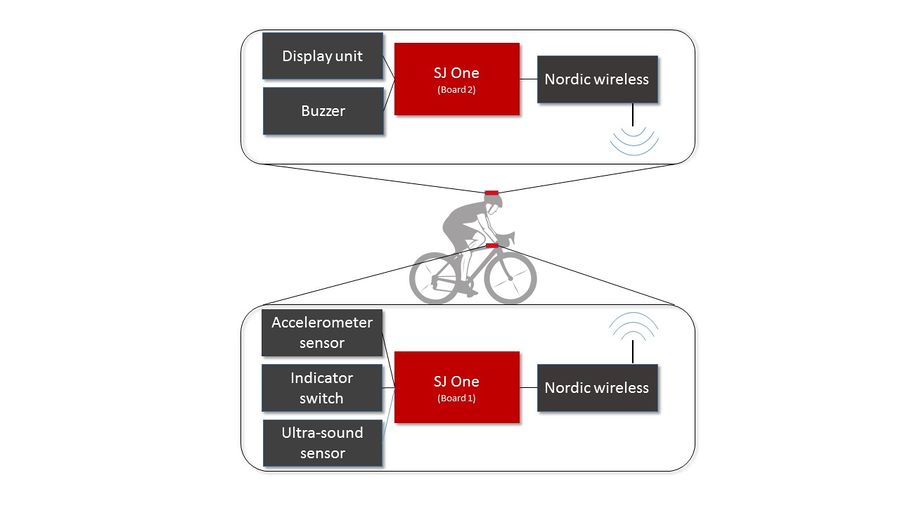
An overview of the system is as shown in the figure below. Two SJOne boards have been used for the project. One of them is placed at the rear end of the handle (Board 1) and the other on the helmet (Board 2). Board 1 is interfaced with the accelerometer and ultrasound sensors. Board 2 is interfaced with a LED display unit and a buzzer. Both these boards communicate with each other using a Nordic wireless interface module. A more detailed expalination of the working of these modules is given in the sections below.
Team Members & Responsibilities
- Abhay Prasad
- Motion analysis dataset collection
- Designed algorithm for Motion Analysis Engine
- Designed hardware and software for ADA module
- Overall product design.
- Revathy
- Designed hardware and software for warning system
- Developed application Algorithm
- Built hardware circuit
- Integrated the functionality to the main project
- Unit testing, verification, and validation of the module
- Unnikrishnan
- Product and API Design
- Main Controller Design and Development
- Code integration
- Integration Testing
- Motion Analysis Dataset collection framework
- Vishalkumar
- Designed Wireless channel Interface module
- Functionality integration to MHI
- Hardware support
- Kripanand Jha
- Schematic and PCB design
- Component soldering on PCB
- Implemented UIO APIs
Schedule
This section of the report provides the team schedule for the Halo Smart Helmet project, indicating the milestones to be achieved during the course of the project.
| Week# | Date | Task | Actual |
|---|---|---|---|
| 1 | 03/21 | Team Discussion on understanding and finalizing requirements; Identify extra hardware requirements | Completed |
| 2 | 03/28 | Design Hardware and Software modules;Finalize on schematic; Purchase h/w components. | Completed |
| 3 | 04/04 | Interface Accelerometer & Ultrasound sensors; Finalise API layer for individual modules | Completed |
| 4 | 04/11 | Implement modules - start/stop detect algo,distance detect algo,Wireless comm,LED-Display Pane | Completed |
| 5 | 04/18 | Interface system with wireless modules; PCB design | Completed |
| 6 | 04/25 | SW & HW unit testing | Completed |
| 7 | 05/02 | System level Integration & testing | Completed |
| 8 | 05/09 | OnRoad testing /Blackbox testing | Completed |
| 9 | 05/16 | Project Demo | Planned |
Parts List & Cost
| Parts# | Part Name | Quantity | Cost Unit Item |
|---|---|---|---|
| 1 | Bike | 1 | Free |
| 2 | Helmet | 1 | Free |
| 3 | 9 V DC battery | 4 | 3.00 $ |
| 4 | Wireless Antenna | 2 | 2.20 $ |
| 5 | SJOne Board | 2 | 80 $ |
| 6 | PCB fabrication | 10 | 2.8 $ |
| 7 | Ultrasound sensor | 1 | 6 $ |
Design & Implementation
The design and implementation of each of these modules were done separately and finally integrated using the MHI module. Since each module has its own challenges and complexity, we have decided to organize this sections according to the work done on individual modules. After the detailed description of each of these modules an overall picture of the working of the system can be seen.
Motion Analysis Engine Module (MAE)
The motion analysis engine plays a significant role in alerting the surrounding of the cyclist. This is an intelligent module that detects the cyclist's actions (moving / slowing down / stopped). According to the action performed by the cyclist, an appropriate indication is given on the helmet. Since this module is required to automatically detect the action of the cyclist, several meticulous steps were followed while designing this module. The accelerometer plays a major role in designing this module.
Hardware design and interface
The MMA8452Q accelerometer [2] by Fress scale semiconductors was used to recognize the action of the cyclist in real time. This is housed on the SJOne board. and provides us with acceleration values which can be made use of to determine the state of the cyclist during transit. The internal structure of accelerometer is suspended by polysilicon springs which allow them to deflect when subject to acceleration in the X, Y and/or Z axis. The deflection causes a change in capacitance between fixed plates and plates attached to the suspended structure. This change in capacitance on each axis is converted to an output voltage proportional to the acceleration on that axis. These voltages are stored in appropriate registers on the accelerometer IC and can be read through an I2C interface.
In this project, we make use of the accelerometer readings in the x-axis. Since the action of the cyclist is performed mostly in one direction, readings from a single axis of the accelerometer is sufficient to determine if the cyclist is in moving / slowing down / stopped. The placement of the accelerometer is such that the acceleration values on the x-axis are positive when the cycle moves forward and negative if it moves backward.
Algorithm design
The quantitative response of the accelerometer was unknown for the cyclist for different actions. In order to evaluate the response, accelerometer readings with a sampling rate of 10ms were logged into a file for various actions performed by the cyclist in real time environments. A video of the cyclist in sync was also recorded to evaluate the accelerometer responses.
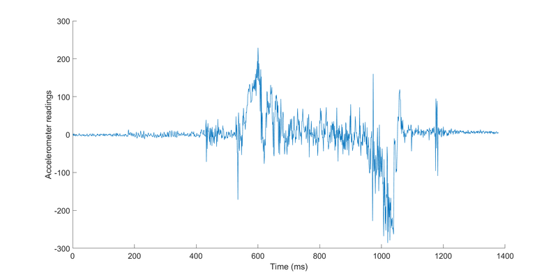
The recorded accelerometer readings was first processed using Matlab. Matlab served to be of significant help in prototyping the algorithm for motion analysis. This helped us visualize and gain a clear picture of the response of the accelerometer readings. Figure below shows the response of the accelerometer when the cyclist performs stop->accelerate->slow_down->stop. The amount of noise present in the signal is significant thus, making it very difficult to interpret the signal.
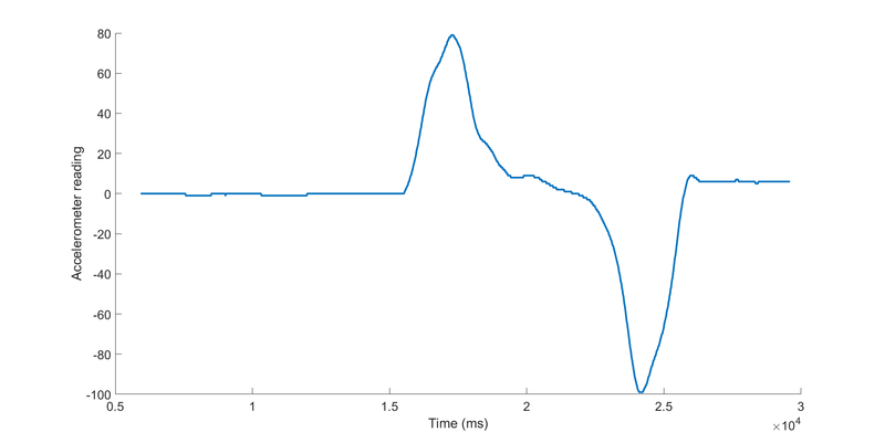
A moving averaging filter [2] of length 100 was required to effectively denoise the signal. The operation of the moving averaging filter is simple. For an n-point moving averaging filter, n samples are recorded and the average of these samples is used as the output. For embedded systems, this operation serves to be very a simple and effective solution for denoising as it is performed with less number of computations when compared to other denoising techniques. The figure below shows the denoised output after filtering. As you can see, the accelerometer readings can now be interpreted easily.
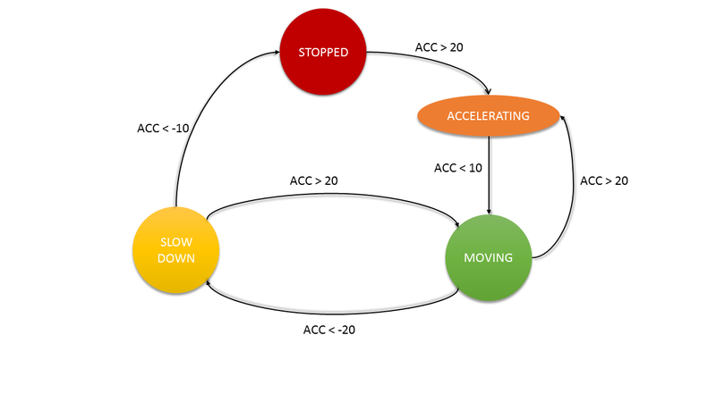
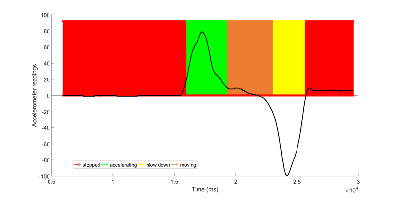
The accelerometer reading stays at 0 and is constant when the cyclist is at rest (stopped). As the cyclist accelerates, a peak in the signal can be seen and the accelerometer readings come to rest again. When the cyclist slows down and comes to a stop, there is a dip followed by a constant reading of 0. As you can see, the accelerometer readings are at 0 when the cyclist comes to stop as well as when the cyclist is in motion with a constant speed. This serves as a challenge to solve in determining if the cyclist has stopped or is in motion. An effective solution to deal this is by using state machines. The acceleration curves followed by 0 values can be interpreted as the cyclist is in motion and 0 values followed by a dip can be interpreted to be a stop.
The figure below shows the state machine designed considering all the various thresholds for state transitions between stop, slow down, and moving. An additional state of accelerating is used to help make the algorithm more robust.
The output of the designed state diagram of the exemplary accelerometer readings is shown in the plot below. The same color code is used to represent the different states specified in the state diagram. As you can see, the algorithm is set to clearly distinguish between moving and stop states of the cyclist though the values obtained in those states are the same.
Implementation
The MAE module as a whole is implemented as a task on the SJOne board mounted on the cycle (Board 1). This task is set to perform motion analysis every 10ms, hence a vTaskDelay() is used. It must be noted that the factory zero-offset values do not hold valid for the MMA8452Q accelerometer. This is due to the external stress that is caused to the IC when it was mounted onto the PCB. Since this is an external factor affecting the IC, the amount of offset for different boards was found to vary. Hence, a calibration constant is calculated by logging the values of the accelerometer for approximately 300ms after startup of the microcontroller. The mean of the values logged in this 300ms window is used as the calibration constant. The exemplary plots of accelerometer readings shown in the above section are after offsetting from the calibration value. The implementation of the moving averaging filter is shown in the snippet below:
/**
 * ABSTRACT: This function performs the function of a moving average filter.
 * 	     The mean of values specified by the window size is used to obtain the
 * 	     output of the kernel.
 *
 * INPUTS: in - pointer to the array containing data.
 *         window_size - number of elements in the input array (in).
 *         val - value to append to the array.
 *
 * OUTPUTS: None.
 *
 * RETURNS: Output of the kernel after performing moving averaging.
 */
int16_t moving_average_filter (int16_t *in, int16_t val, uint16_t window_size){

	/*
	 * Shift the array and append new value.
	 */
	 memmove(&in[1],&in[0],sizeof(int16_t)*(window_size-1));
	 in[0] = val;

	 /*
	  * Compute average after appending new value to the array
	  * and removing last value.
	  */
	double sum = 0;
	for (uint16_t i = 0; i < window_size; i++){
		sum += in[i];
	}
	return (int16_t)(sum/window_size);
}
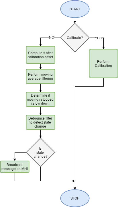
The overall implementation of the MAE is as shown in the flowchart below. After calibration, the accelerometer readings are zero offset and fed into the moving averaging filter. The core algorithm of determining the state of cyclist is done in this phase. A debouncing filter is used to post filter the state changes. If a valid state change is detected, the corresponding message indicating the state of the cyclist is broadcasted to the ADA module for displaying.
Ultra Sound Sensor Module (USS)
One of the features of Halo Smart Helmet is to provide a warning signal to the biker when there is vehicle close to him. The Ultrasonic sensor module is used to detect the vehicle range and indicate the warning levels based on the detected range of the vehicles. This module is required to send, Warning Level 1 when the vehicle is in range 2-3 m Warning Level 2 when the vehicle is in range <=1 m
Hardware Design and Interface
An ultrasonic distance sensor HC-SR04, using sound waves, can detect an object located within its field of view. It works by sending out high-frequency sound waves (a.k.a Chirps) and receiving the Echo signal from an object in the sensor range. The received pulse width is then measured to find the distance of the object.The ultrasonic sensor can detect objects anywhere from 2 cm to 400cm (157 inches or 13 feet) within 15° measuring angle.A trigger pulse of 10-microsecond is required for the sensor to enter the ranging mode. In the ranging mode, the sensor internally generates 8 pulses of 40 kHz at the transmitter side. The reflected sound wave (Echo) is detected at the receiver side. The Echo pulse is started after Transmission of Chirps is complete and it ends when the last chirp among the 8 pulses is echoed back.
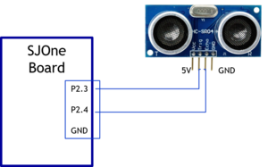
The Trigger and Echo pin of the sensor is connected to the GPIO port pins of SJOne board.The trigger is generated by toggling the port pin with a delay of 10us, and the echo receives pins are designed to use GPIO interrupts to measure the pulse width. Since the rising and falling edge of the same pin is not detected, the issue is resolved by using two port pins, for registering EINT3 rising and falling edge interrupts.
Algorithm design
- Create RTOS Task with Medium priority
- Register for GPIO rising and falling edge interrupts
- Start Soft timer with period of 200ms
- Once the timer expires, Trigger the USS module to run in ranging mode
- On receiving rising edge interrupt, the callback stores the Timer0 value
- n receiving falling edge interrupt, the callback stores the Timer0 value
- The Echo duration is calculated using the stored time and Distance is calculated using the above function.
- The distance is compared with the warning level range and warning signals are updated.
- The warning signal is sent to the controller task which notifies the biker with sound alert.
Software design
This module task runs every 200ms cycle to check the range of the vehicles surrounding the biker.The sensor can detect a maximum range of 4m, so the warning levels are set as if the distance of the vehicle is more than 2m, Level 1 warning is signaled if distance is less than 2m level 2 warning is signaled.The warning levels are notified with different alert sounds to the biker.So the warning levels are broadcasted to AlertDisplayModule of the system
A FreeRTOS task is created for USS module to trigger and detect the Echo pulse at 200 ms cycle.The pulse width is measured by the GPIO interrupt callbacks and distance is calculated using formula
                            Distance = Speed of sound * Echo pulse width/2
                                     = (340 *100) / (10^6*(Echo/2)) cm/us * tp us
                                     = 0.017 cm/us *  Echo
Implementation
The communication between the module and peripherals is through GPIO EINT3 interrupt. The interrupt callbacks are registered in Init() function.The communication between the USS_Task and ISR is through FreeRTOS queue mechanism. When the falling edge ISR runs, the saved timer0 value is passed to the task via a queue, the task which is blocked on the queue is woken to calculate the distance and broadcast to AlertDisplayModule to notify the biker with sound.
USS_Init()
{
   Timer0_Enable(lpc_timer0)
   Configure_GPIO(Pin2.3,Output)
   ClearGPIOPins(3,4,5)
   EINT3_Enable(Pin2.4,eint_falling_edge,falling_isr_callback)
   EINT3_Enable(Pin2.5,eint_rising_edge,raising_isr_callback)
   TriggerTimerStart(200ms)
}
USS_PeriodicTriggerTask()
{
if(TriggerTimerExpired())
GeneratePulse(10us)
startTime = Timer0_Read(lpc_timer0);
if(xQueueReceive(endtime))
{
Echo = endtime-startTime
Distance= Echo * 0.017
SetandBroadcastWarning()
}
TriggerTimerRestart();
}Testing & Verification
User Input Output Module (UIO)
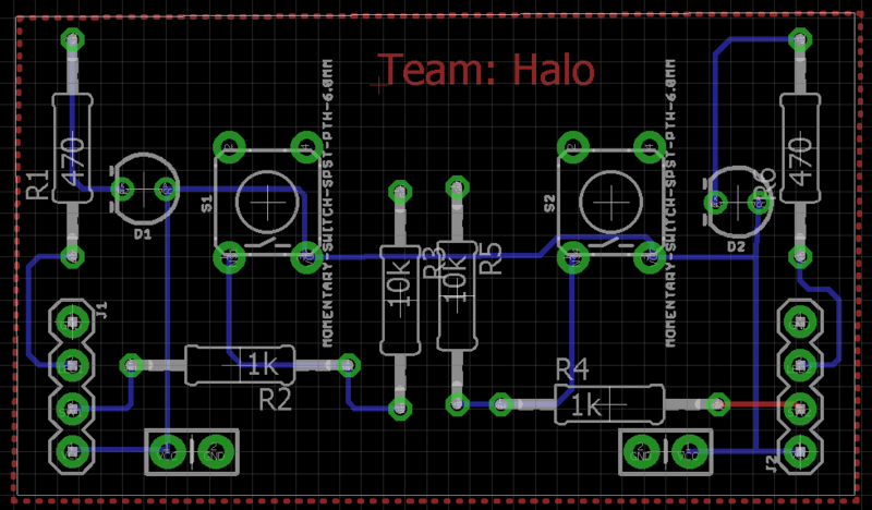
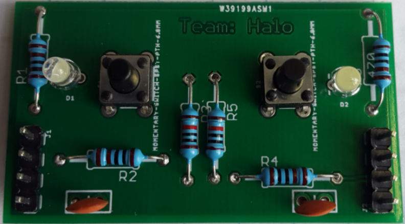
The indicators on the bike serve to be of great help when changing lanes and taking turns. This avoids the cyclist to extend his hand to indicate turns, thus making it more convenient to ride in high traffic areas where lane changing must be done with utmost care. Two buttons and LEDs are used to indicate in this module to implement the function of indicators. The buttons trigger for the action of the indicators to be displayed on the helmet and LED on the indicator panel helps the cyclist to recognize the state of the indicators.
Hardware design
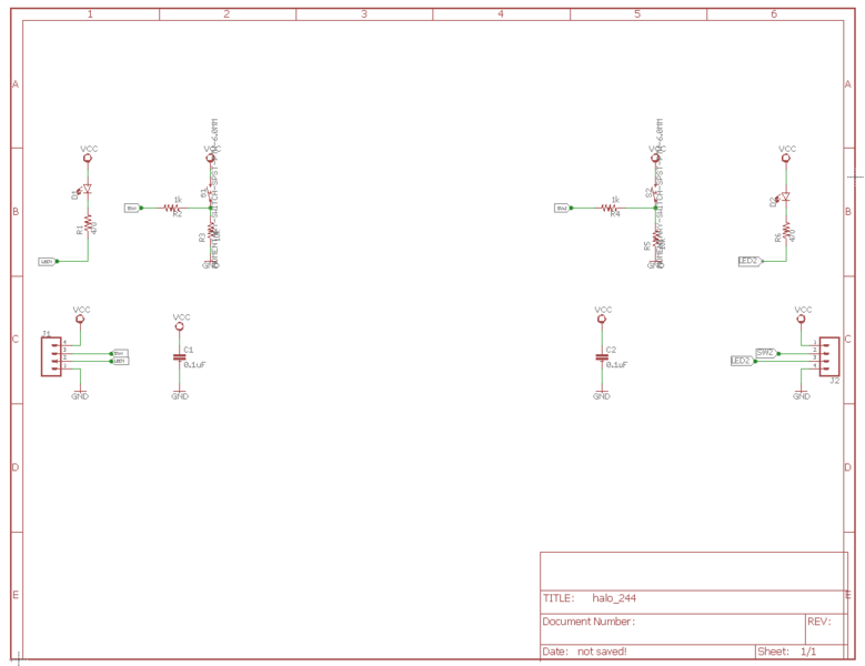
A PCB was designed to implement this functionality. We designed custom 28.2 x 48.8 mm board for our project. The goal of the PCB design was to learn the basics of PCB designing using EAGLE software as it is one of the parts of embedded systems. We have added two switches along with two LEDs for showing left-right direction while turning the bike. We added connectors on the board to further connect the switch to the external board and also connect the power and ground to the external circuit.
To design our board we used AUTODESK EAGLE application. We designed schematics and PCB for our board in EAGLE. This board will be interfaced with SJOne board's GPIO, power and GND pin. For the schematic design, we used SparkFun library components like switches, LEDs, connector, resistors. After done with schematics, EAGLE generates board design based on schematics we create. Inboard design it's on you how you minimize the board space place your components in the board. After done with the proper design we can either opt for auto-routing or manual routing thing to route the various components in the board. While routing, use proper values of width and drill size for the route. After done with routing check for any errors in the board connections using ERC and DRC tools. We designed dual layer pcb just for the sake of testing. for the common ground, we used ground polygon that makes circuit design simpler. While routing note down the drill size and width of traces it must be sufficient enough to for current flow in the wire.
| Parts# | Part Name | DEVICE | LIBRARY | PACKAGE |
|---|---|---|---|---|
| 1 | LED | LED-3MM-NO_SILK (LED) | SparkFun-LED | LED_3MM-NS |
| 2 | SWITCH | MOMENTARY-SWITCH-SPST-PTH-6.0MM (MOMENTARY-SWITCH-SPST) | SparkFun-Switches | TACTILE_SWITCH_PTH_6.0MM |
| 3 | Connectors | CONN_04 | SparkFun-Connectors | 1X04 |
| 4 | Capacitors | 0.1UF-KIT-EZ-50V-20% (0.1UF) | SparkFun-Capacitors | CAP-PTH-SMALL-KIT |
Hardware Interface
The UIO Module is interface on board one (transmitter) side. It has two leds, two switches which is connected to SJONE GPIO pins. The UIO board is attached near to the Board one at cycle handle so that it will be easy for cyclist to pressed the UIO switch when taking turn or changing lane.
Software design
Implementation
Wireless Interface Controller (WIC)
Hardware design and Implementation
Wireless interface controller enables communication between two boards. This module uses Nordic nRF24L01 transceiver to send the wireless messages which are coming from Motion Analysis Engine Module (MAE), Ultra Sound Sensor Module (USS) and User Input Output Module (UIO) through Message Handler Interface(MHI).WCI module uses built-in wireless.h APIs.
Initialization of Nordic transceiver has been done by setting up the communication parameters like node address air data rate, Channel frequency, and channel frequency. Both boards should have same parameters configuration except Node address. Node Address is a unique address used by the controller to identify the nodes in the networks. In WCI module, auto address detection functionality implemented to detect Board-2(receiver board) address. Air data rate(supported 250 kbps, 1Mbps, 2Mbps) is the modulating signaling rate that is used by nRF24L01+ for transmitting and receiving data. Here, we are using smaller data rate, 250 kbps, to minimize data corruption and reduce the power consumption. Channel Number/frequency is used differentiate the different mesh networks. Since we are using only two board, we can configure this parameter to any value between 2402-2500(2.402GHa-2.5GHz).
Software Design
Transmitter and receiver boards use similar initialization except for Node address. Inbuilt mesh network API has been used to implement Wireless Interface Controller (WIC).
TX program flow:
- Initialization
- Set source address (Node address), Destination address, number hops and other parameters
- Create mesh packet by encapsulating these parameters and message
- Send packet using mesh API
- Wait for ACK
- If ACK is not received in specific time, resend the packet
RX program flow:
- Initialization
- Set source address (Node address), Destination address, number hops and other parameters
- Check for any received packet in the queue
- If packet is received, extract the message
- Send this message to other modules through Message Handler Interface (MHI)
Alert Display Array module (ADA)
The warning signals from each of the modules are displayed on the helmet to effectively alert the cyclist's surroundings. The ADA system continuously monitors for signals from MAE, USS and the UIO modules. As soon as it receives alerts, the corresponding warning signal is displayed on the helmet.
Hardware Implementation
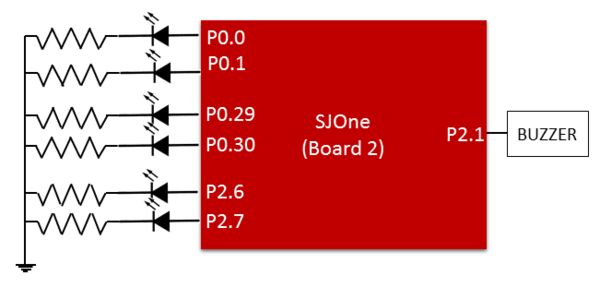
A total of seven GPIO pins has been used to indicate warning signals. Six of these pins have been connected to LEDs and the remaining one pin to the buzzer. The table below shows the use of different pins for implementing the system on the helmet (Board 2).
| Component | Purpose | GPIO pin |
|---|---|---|
| Yellow LED | Left indicator | P0.0 |
| Yellow LED | Left indicator | P0.1 |
| Yellow LED | Right indicator | P0.29 |
| Yellow LED | Right indicator | P0.30 |
| Red LED | Motion indicator | P2.6 |
| Red LED | Motion indicator | P2.7 |
| Buzzer | Warning from USS | P2.1 |
A total of 2 LEDs connected to separate GPIO pins is used to indicate each of the functionalities above. As soon as the button on the UIO module is triggered for indicators, the display on the helmet goes off as well. The indicators for each side blink for a total of 5 seconds for each button press. The motion indicator gets its input from the MAE. During motion of the cyclist, the LEDs blink every 100ms and when the cyclist slows down, the LEDs blink more rapidly, thus effectively alerting the surrounding of the cyclist.
The Buzzer is used to indicate the warning signal for the cyclist and is triggered from the USS module. A passive buzzer has been used so that different levels of sound can be realized for warning and critical alert to the cyclist. PWM pulse of varying duty cycle is used to vary the sound levels.
The figure below shows the schematic of the circuit used to implement the ADA module.
Software Implementation
The buzzer, indicators and motion display system work independently. Hence, each of these has been created as a task of their own. All these tasks have the same priority hence, a simple implementation was used to design the ADA module. Simple delays were used in each of tasks that involved the blinking of LEDs. The inbuilt PWM API in the freeRTOS project was used to generate the pulse for the passive buzzer.
Basic Software Architecture
Board 1 (SJOne on the bike)
In our design, the board 1 (board on the bike) takes care of motion analysis, unsafe approaching vehicle detection, and the user input handler (used for the bike's indicator switches). Thus, this board runs 5 logical blocks namely:
a) MAE (thread of MEDIUM priority - Timer driven)
b) USS (thread of MEDIUM priority - Timer and Interrupt driven)
c) UIO (thread of MEDIUM priority - Interrupt driven)
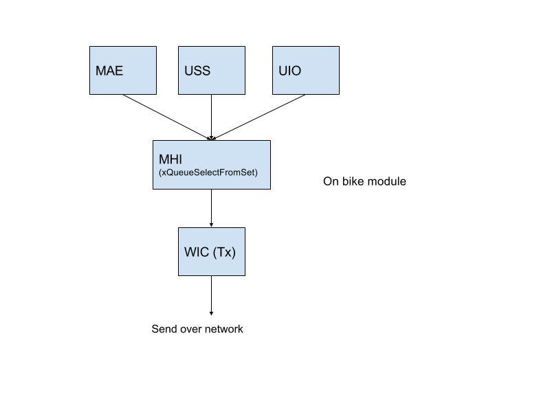
d) MHI (thread of MEDIUM priority)
e) WCI TX (runs in the context of MHI)
The modules MAE, USS and UIO are responsible for generating timely events and all of them need equal share of the CPU to perform their tasks. But, as we can imagine, the USS module which warns about an unsafe vehicle distance on the rider's blind spot generates the most important event which needs to be sent to the helmet ADA (Alert Display Array) module first. To maintain this priority, we implement a priority queue scheme with MHI.
Board 2 (SJOne on the helmet)
In our design, the board 2 (board on the helmet) takes care of ADA (Alert Display Array) which uses WCI-RX to receive events from Board 1 to categorise and display alerts on the ADA panel. This, this board runs 3 logical blocks namely:
a) WIC RX (thread of MEDIUM priority - Interrupt driven - uses the wireless mesh API at L4_IO/wireless/wireless,h)
b) MHI (runs from the context of WIC RX)
c) ADA (runs from the context of MHI)
The WIC RX module is responsible for receiving the event message sent over the wireless mesh from Board 1, formulate the tHalo_Msg object and broad cast the object using the MHI gHalo_MHI_BroadCast() API which internally calls the gHalo_ADA_Show() lightweight API to trigger Alert mechanisms.
Message Handler Interface (MHI)
The Message Handler Interface is responsible for sending out an event packet over WCI-TX, but still need to prioritise the events as described above.
Implementation
gHalo_MHI_BroadCast() API provided is used by USS, MAE and UIO to broadcast their events which get asynchronously handled in the MHI. MHI on the other hand uses a QueueSet implementation which blocks on the availability of event(s) from any of the user blocks (namely USS, MAE and UIO). As soon as an event is available, the xQueueSelectFromSet() API unblocks providing MHI the opportunity to prioritise event message dequeue. The prioritisation mechanism follow a simple rule assuming the queue at the lower index of the Queue array is the highest priority. So, the implementation do a simple loop starting with the highest priority queue (USS) check and dequeue through to the lowest priority dequeue (UIO).
Testing & Technical Challenges
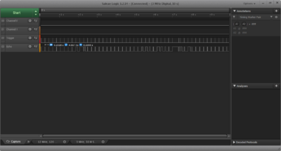
Testing was done for each of the modules individually before integration. The methodologies for testing varies between different modules. The MAE was built on logging the accelerometer data and later processing it on Matlab. Since we logged data for a total of five times, the algorithm was easily tested on Matlab. Apart from the simulated tests on Matlab, fine tuning of the algorithm parameters and testing was done when I used to ride from home to college. The ultrasound sensor module had to be tested manually by placing obstacles in front of the sensor at different distances. Also, the logic analyzer came to great help to see the rising and falling edges provided by the ultrasound sensor.
Coming up with an algorithm when dealing with sensors seems challenging, especially when data has to be logged. If this project has to be started again, we recommend cross-checking the code at least 5 times before starting to log data. Setting up environments to log data and having a bug in the code would serve to be a great waste of time.
The overall testing phase for the project involved cycling in high traffic areas. We rode the cycle around the downtown with the system to check for responses in heavy traffic conditions. A few of the issues we encountered and the solutions to those are given below:
My Issue #1
EINT3 API provided with freeRTOS project does not support the use of multiple triggers on the same pin
- The USS module requires rising and falling edge interrupts to measure the distance from the ultrasound sensors. This was resolved by connecting the output of the ultrasound sensor to 2 different interrupt pins on the SJOne board.
My Issue #2
Some packets were getting dropped for the Nordic wireless module
- Initially, boards were configured for 2Mbps data rate in which Some packets were getting dropped. Since we don't require higher data rate, we chose 250kbps data rate to solve this issue.
My Issue #3
The range of accelerometer values varies across boards:
- As discussed in the above section, the accelerometer factory offsets do not zero-offset the readings. This was due to the external forces acting upon the IC. The solution to resolving this problem was to compute a calibration offset just after startup of the microcontroller.
Conclusion
We successfully completed implementing all the proposed objectives.
Project Video
Video coming soon....
Project Source Code
Surce code coming soon...
References
Acknowledgement
We would like to thank Preet for providing the opportunity to apply ourselves with the theoretical concepts learned in class.
References Used
[1] Golestan, Saeed, et al. "Moving average filter based phase-locked loops: Performance analysis and design guidelines." IEEE Transactions on Power Electronics 29.6 (2014): 2750-2763.
[2] MMA8452Q, Xtrinsic. "3-Axis, 12-Bit/8-Bit Digital Accelerometer." 2013-10]. http://cache. freescale. com/files/sensors/doc/data_sheet/MMA8452Q. pdf (2014).
