F16: Kasper
Contents
- 1 Project Title
- 2 Abstract
- 3 Objectives & Introduction
- 4 Team Members & Responsibilities
- 5 Team Schedule
- 6 Parts List & Cost
- 7 DBC File Implementation
- 8 Sensor Controller
- 9 Motor & I/O Controller
- 10 Geographical Controller
- 11 Communication Bridge Controller
- 12 Master Controller
- 13 Conclusion
- 14 References
Project Title
Self Driving Car
Abstract
This project implements a self-driving car.
Objectives & Introduction
Objective of this project is to create a self driving car
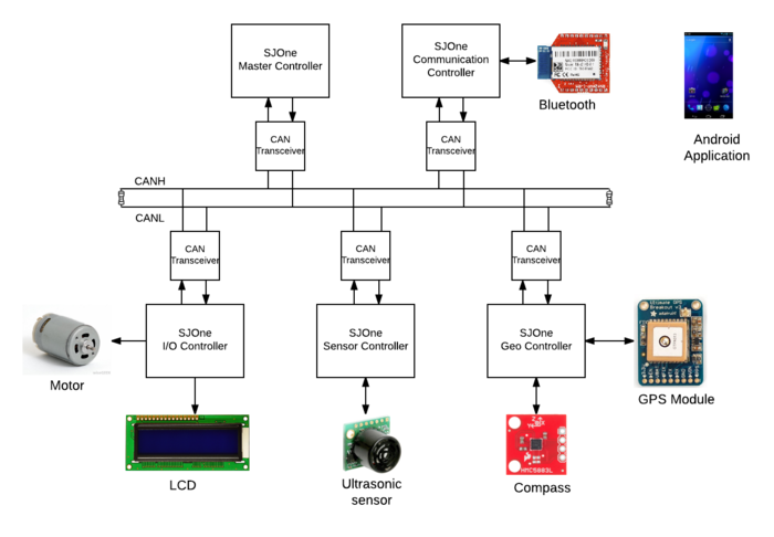
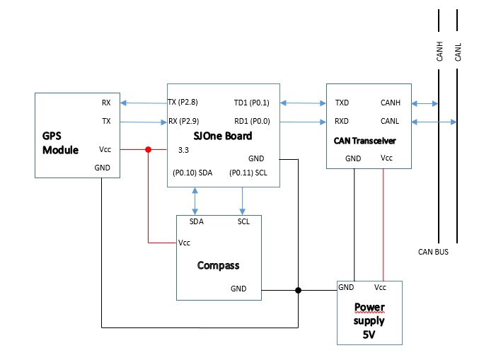
System Block Diagram
Team Members & Responsibilities
We have used five controllers
- Sensor Controller
- Shruthi Narayan
- Rimjhim Ghosh
- Color coding: Text
- Motor & I/O Controller
- Prashant Aithal
- Chethan Keshava
- Color coding: Text
- Geographical Controller
- Ankit Gandhi
- Color coding: Text
- Master Controller
- Aajna Karki
- Spoorthi Mysore Shivakumar
- Color coding: Text
- Communication Bridge Controller
- Bharat Khanna
- Shantanu Vasishtha
- Color coding: Text
Team Schedule
| Sl No. | Start Date | End Date | Task | Status | Actual Completion Date |
|---|---|---|---|---|---|
| 1 | 09/20/2016 | 09/27/2016 |
|
Completed | 09/27/2016 |
| 2 | 09/28/2016 | 10/04/2016 |
|
Complete | 10/04/2016 |
| 3 | 10/05/2016 | 10/11/2016 |
|
Completed | 10/11/2016 |
| 4 | 10/12/2016 | 10/18/2016 |
|
Completed | 10/18/2016 |
| 5 | 10/19/2016 | 11/01/2016 |
|
Completed | |
| 6 | 11/01/2016 |
CAN COMMUNICATION DEMO |
Completed | ||
| 7 | 11/01/2016 | 11/07/2016 |
|
Completed | |
| 8 | 11/08/2016 |
PROJECT PROTOTYPE DEMO |
Completed | ||
| 9 | 11/08/2016 | 11/15/2016 |
|
Completed | |
| 10 | 11/16/2016 | 11/29/2016 |
|
Completed | |
| 11 | 11/29/2016 |
PROJECT PROTOTYPE DEMO 2 |
Completed | ||
| 12 | 11/29/2016 | 12/06/2016 |
|
Completed | |
| 13 | 12/07/2016 | 12/15/2016 |
|
Completed | |
| 14 | 12/17/2016 |
FINAL PROJECT DEMO |
Upcoming Task | ||
| 15 | 12/20/2016 |
PROJECT REPORT SUBMISSION |
Upcoming Task | ||
Parts List & Cost
| Item# | Part Desciption | Vendor | Qty | Cost $ |
|---|---|---|---|---|
| 1 | RC Car | From Preet | 1 | 0 |
| 2 | SJOne board | Preet | 5 | 80 |
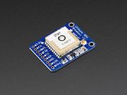
| 3 | GPS Module | Adafruit | 1 | 40 |
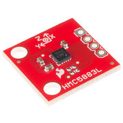
| 4 | Triple Axis Magnetometer (Compass) | Sparkfun | 1 | 15 |
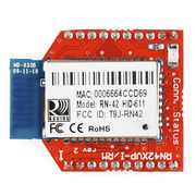
| 5 | Bluetooth Module | Sparkfun | 1 | 24.95 |
| 6 | LCD screen | Adafruit | 1 | 24.95 |
| 7 | Ultrasonic sensor | Sparkfun | 1 | 27.95 |
| 8 | Jumper cable | Amazon | 1 | 9.99 |
| 9 | DB9 Connector | HSC | 1 | 1 |
| 10 | CAN Transceiver | Microchip | 10 | 10 |
DBC File Implementation
The DBC file used for the project is as below:
VERSION ""
NS_ :
 BA_
 BA_DEF_
 BA_DEF_DEF_
 BA_DEF_DEF_REL_
 BA_DEF_REL_
 BA_DEF_SGTYPE_
 BA_REL_
 BA_SGTYPE_
 BO_TX_BU_
 BU_BO_REL_
 BU_EV_REL_
 BU_SG_REL_
 CAT_
 CAT_DEF_
 CM_
 ENVVAR_DATA_
 EV_DATA_
 FILTER
 NS_DESC_
 SGTYPE_
 SGTYPE_VAL_
 SG_MUL_VAL_
 SIGTYPE_VALTYPE_
 SIG_GROUP_
 SIG_TYPE_REF_
 SIG_VALTYPE_
 VAL_
 VAL_TABLE_
BS_:
BU_: DBG MASTER GEO SENSOR MOTORIO BRIDGE
BO_ 100 STOP_CAR: 1 MASTER
 SG_ STOP_CAR_data : 0|8@1+ (1,0) [0|0] "" BRIDGE,GEO,SENSOR,MOTORIO,DBG

BO_ 110 RESET: 1 MASTER
 SG_ RESET_data : 0|8@1+ (1,0) [0|0] "" BRIDGE,GEO,SENSOR,MOTORIO,DBG
BO_ 120 POWER_SYNC_ACK: 1 MASTER
 SG_ POWER_SYNC_ACK_data : 0|8@1+ (1,0) [0|0] "" BRIDGE,GEO,SENSOR,MOTORIO,DBG
BO_ 130 STOP_CMD_APP: 1 BRIDGE
 SG_ STOP_CMD_APP_data : 0|8@1+ (1,0) [0|0] "" MASTER,DBG

BO_ 140 START_CMD_APP: 1 BRIDGE
 SG_ START_CMD_APP_data : 0|8@1+ (1,0) [0|0] "" MASTER,DBG
BO_ 200 MOTOR_POWER_SYNC: 1 MOTORIO
 SG_ MOTOR_POWER_SYNC_data : 0|8@1+ (1,0) [0|0] "" MASTER,DBG

BO_ 210 SENSOR_POWER_SYNC: 1 SENSOR
 SG_ SENSOR_POWER_SYNC_data : 0|8@1+ (1,0) [0|0] "" MASTER,DBG

BO_ 220 BRIDGE_POWER_SYNC: 1 BRIDGE
 SG_ GEO_POWER_SYNC_data : 0|8@1+ (1,0) [0|0] "" MASTER,DBG

BO_ 230 GEO_POWER_SYNC: 1 GEO
 SG_ BRIDGE_POWER_SYNC_data : 0|8@1+ (1,0) [0|0] "" MASTER,DBG
BO_ 300 MOTORIO_HEARTBEAT: 1 MOTORIO
 SG_ MOTORIO_HEARTBEAT_data : 0|8@1+ (1,0) [0|0] "" MASTER,DBG

BO_ 310 SENSOR_HEARTBEAT: 1 SENSOR
 SG_ SENSOR_HEARTBEAT_data : 0|8@1+ (1,0) [0|0] "" MASTER,DBG

BO_ 320 BRIDGE_HEARTBEAT: 1 BRIDGE
 SG_ BRIDGE_HEARTBEAT_data : 0|8@1+ (1,0) [0|0] "" MASTER,DBG

BO_ 330 GEO_HEARTBEAT: 1 GEO
 SG_ GEO_HEARTBEAT_data : 0|8@1+ (1,0) [0|0] "" MASTER,DBG
BO_ 400 SENSOR_SONIC: 4 SENSOR
 SG_ SENSORS_SONIC_front_left : 0|8@1+ (1,0) [0|0] "" MASTER,MOTORIO,DBG
 SG_ SENSORS_SONIC_front_right : 8|8@1+ (1,0) [0|0] "" MASTER,MOTORIO,DBG
 SG_ SENSORS_SONIC_front_center : 16|8@1+ (1,0) [0|0] "" MASTER,MOTORIO,DBG
 SG_ SENSORS_SONIC_back : 24|8@1+ (1,0) [0|0] "" MASTER,MOTORIO,DBG

BO_ 410 MOTORIO_DIRECTION: 3 MASTER
 SG_ MOTORIO_DIRECTION_speed : 0|8@1+ (1,0) [0|10] "" MOTORIO,DBG
 SG_ MOTORIO_DIRECTION_turn : 8|8@1+ (1,-4) [-3|3] "" MOTORIO,DBG
 SG_ MOTORIO_DIRECTION_direction : 16|8@1+ (1,0) [0|2] "" MOTORIO,DBG
BO_ 420 BRIDGE_TOTAL_CHECKPOINT: 1 BRIDGE
 SG_ BRIDGE_TOTAL_CHECKPOINT_NUMBER : 0|8@1+ (1,0) [0|0] "" MASTER,MOTORIO,DBG

BO_ 430 RECEIVE_START_ACK: 1 MASTER
 SG_ RECEIVE_START_ACK_ack : 0|8@1+ (0,0) [0|0] "" BRIDGE,DBG

BO_ 440 BLUETOOTH_DATA: 8 BRIDGE
 SG_ BLUETOOTH_DATA_LAT : 0|32@1+ (0.000001,0) [0|0] "" MASTER,DBG
 SG_ BLUETOOTH_DATA_LON : 32|32@1+ (0.000001,0) [0|0] "" MASTER,DBG
BO_ 450 NEXT_CHECKPOINT_DATA: 8 MASTER
 SG_ NEXT_CHECKPOINT_DATA_latitude : 0|32@1+ (0.000001,0) [0|0] "" GEO,DBG
 SG_ NEXT_CHECKPOINT_DATA_longitude : 32|32@1+ (0.000001,0) [0|0] "" GEO,DBG

BO_ 460 COMPASS_DATA: 5 GEO
 SG_ COMPASS_DATA_speed : 0|8@1+ (1,0) [0|0] "" MASTER,DBG
 SG_ COMPASS_DATA_heading : 8|16@1+ (1,0) [0|0] "" MASTER,DBG
 SG_ COMPASS_DATA_bearing : 24|16@1+ (1,0) [0|0] "" MASTER,DBG

BO_ 470 CURRENT_LOCATION_ACK: 1 BRIDGE
 SG_ CURRENT_LOCATION_ACK_ack : 0|8@1+ (1,0) [0|0] "" MASTER,GEO,DBG

BO_ 480 GPS_LOCATION: 8 GEO
 SG_ GPS_LOCATION_latitude : 0|32@1+ (0.000001,0) [0|0] "" MASTER,BRIDGE,DBG
 SG_ GPS_LOCATION_longitude : 32|32@1+ (0.000001,0) [0|0] "" MASTER,BRIDGE,DBG

BO_ 490 DISTANCE_TO_DESTINATION: 1 GEO
 SG_ DISTANCE_TO_DESTINATION_data : 0|8@1+ (0,0) [0|0] "" MASTER, MOTORIO,DBG
BO_ 500 BATTERY_STATUS: 1 SENSOR
 SG_ DISTANCE_TO_DESTINATION_status : 0|8@1+ (0,0) [0|0] "" MASTER, MOTORIO,DBG
CM_ BU_ DBG "Debug node used to determine whether the message is received by any other node";
CM_ BU_ DRIVER "Master Controller";
CM_ BU_ SENSOR "Sensor Controller";
CM_ BU_ MOTORIO "Motor I/O controller";
CM_ BU_ BRIDGE "BRIDGE Controller";
CM_ BU_ GEO "Geo Controller";
CM_ BO_ 2 "Sync message used to synchronize the controllers";
BA_DEF_ "BusType" STRING ;
BA_DEF_ BO_ "GenMsgCycleTime" INT 0 0;
BA_DEF_ SG_ "FieldType" STRING;
BA_DEF_DEF_ "BusType" "CAN";
BA_DEF_DEF_ "FieldType" "";
BA_DEF_DEF_ "GenMsgCycleTime" 0;
BA_ "GenMsgCycleTime" BO_ 300	          1;
BA_ "GenMsgCycleTime" BO_ 310	          1;
BA_ "GenMsgCycleTime" BO_ 320	          1;
BA_ "GenMsgCycleTime" BO_ 330             1;
BA_ "GenMsgCycleTime" BO_ 400 	          10;
BA_ "GenMsgCycleTime" BO_ 410             10;
BA_ "GenMsgCycleTime" BO_ 450             10;
BA_ "GenMsgCycleTime" BO_ 460             10;
BA_ "GenMsgCycleTime" BO_ 470             10;
BA_ "GenMsgCycleTime" BO_ 480             10;
Sensor Controller
Team Members & Responsibilities
- Shruthi Narayan
- Rimjhim Ghosh
Schedule
| SI No. | Start Date | End Date | Task | Status | Actual Completion Date |
|---|---|---|---|---|---|
| 1 | 10/5/2016 | 10/11/2016 |
|
Complete | 10/9/2016 |
| 2 | 10/12/2016 | 10/18/2016 |
|
Complete | 10/18/2016 |
| 3 | 10/19/2016 | 10/25/2016 |
|
Complete | 10/25/2016 |
| 4 | 10/26/2016 | 11/1/2016 |
|
Complete | 11/1/2016 |
| 5 | 11/2/2016 | 11/8/2016 |
|
Complete | 11/8/2016 |
| 6 | 11/9/2016 | 11/15/2016 |
|
Complete | 11/15/2016 |
| 7 | 11/16/2016 | 11/22/2016 |
|
Complete | 11/22/2016 |
| 8 | 11/23/2016 | 11/29/2016 |
|
Complete | 11/29/2016 |
| 9 | 11/30/2016 | 12/6/2016 |
|
Complete | 12/5/2016 |
| 10 | 12/7/2016 | 12/17/2016 |
|
In-Progress |
Hardware Design
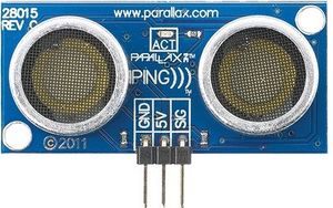
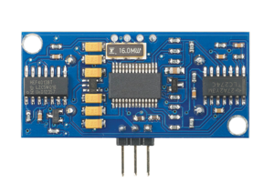
4 Parallax Ping ultrasonic distance sensors are used for this project. They are used for obstacle detection and avoidance. Non-contact distance measurements from about 2 cm (0.8 inches) to 3 meters (3.3 yards).
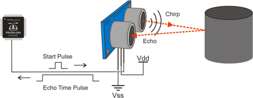
The PING))) sensor works by transmitting an ultrasonic burst and providing an output pulse that corresponds to the time required for the burst echo to return to the sensor. By measuring the echo pulse width, the distance to target can easily be calculated.
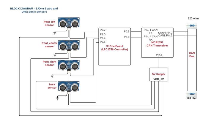
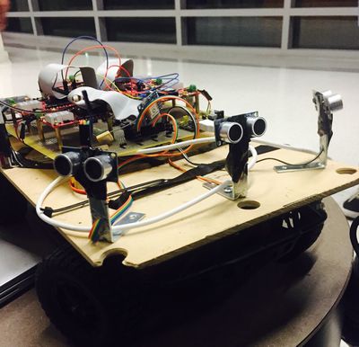
Four Sensors placed in the car, three in front (front_left, front_center, front_right) and one at the back (back). The image below shows the wired connections between sensors and SJOne board.
Software Design
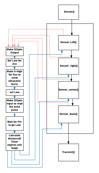
Operation Squence:
Software timer for triggering sensor:
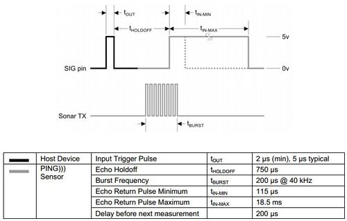
All sensors are triggered using software timers. A soft timer is declared for each sensor which keeps track of the time between trigger and echo for that particular sensor.
#define Echo_Return_Pulse 18.5
SoftTimer ping_duration_left;
ping_duration_left.reset(Echo_Return_Pulse);
ping_duration_left.restart();
if(ping_duration_back.expired())
{
break;
}
Hardware timer for calculating distance: The declaration of hardware timer is as shown below:
lpc_timer_enable(lpc_timer0,1); /*enable timer0*/
lpc_timer_set_value(lpc_timer0,0); /*set timer0 value=0*/
Distance Calculation:
Distance=Speed * Time The distance covered by the sound wave is twice the actual distance.
Therefore, Distance= (Speed * Time)/2
Speed of sound=340m/s, 1m=100cm, 1us=10-6 s
Distance covered in 1us= (340*100*0.000001)/2 = 0.017cm
#define Distance_Scale 0.017
time_left = lpc_timer_get_value(lpc_timer0);
distance_left = (Distance_Scale)*time_left;
Ranging:
LeftSIG.setAsOutput(); /*make SIGpin output*/
LeftSIG.setLow(); /*set low for 2us and then high for clean high*/
delay_us(2);
LeftSIG.setHigh(); /* enable Ranging (enable left sonar). trigger/set high for 2 µs (min), 5 µs typical. Ultrasonic burst*/
delay_us(5);
LeftSIG.setLow(); /*set low*/
LeftSIG.setAsInput(); /*make SIGpin input*/
Implementation
Sensor Testing: LV-MaxSonar-EZ(MB1010):
• This sensor gives a range of 0 inches to 254 inches with a voltage supply of 5V.
• Using multiple ultrasonic sensors in a single system caused interference (crosstalk) so the sensors were triggered sequentially which reduced the fluctuating values
• The range reading time of Maxbotix LV-MaxSonar-EZ1 is 49 ms for a range of 254 inches (6.54 m) requirement was to send all sensor values in 10 Hz. Only 2 sensor values could be sent.
• Having the requirement to send the sensor readings in 10Hz, we reduced the delay between the sensors to 15ms covering a range of 101 inches. Send values of all the four sensors (left, center, right, back) in 10Hz using chaining process.
• Even after this there were frequent abrupt values encountered in the readings so considering the fluctuations and requirement we switched to parallax ping sensors.
Parallax Ping Sensor Testing:
Pin Configuration:
Pin1: GND- Ground pin
Pin2: 5V- Voltage Supply pin
Pin3: SIG- Signal Pin- This emits a short 40Khz burst acting as a trigger pin then the same pin starts listening the echo.
• Provides precise, non-contact distance measurements within a 2 cm to 3 m range • Simple pulse in/pulse out communication requires just one I/O pin • Burst indicator LED shows measurement in progress • 3-pin header makes it easy to connect to a development board, directly or with an extension cable, no soldering required • The PING))) sensor works by transmitting an ultrasonic (well above human hearing range) burst and providing an output pulse that corresponds to the time required for the burst echo to return to the sensor. By measuring the echo pulse width, the distance to target can easily be calculated.
The PING))) sensor detects objects by emitting a short ultrasonic burst and then "listening" for the echo. Under control of a host microcontroller (trigger pulse), the sensor emits a short 40 kHz (ultrasonic) burst. This burst travels through the air, hits an object and then bounces back to the sensor. The PING))) sensor provides an output pulse to the host that will terminate when the echo is detected, hence the width of this pulse corresponds to the distance to the target.
Testing & Technical Challenges
Issue 1: Triggering of Sensors in Parallel
Triggering all the sensors in parallel causes interference between adjacent sensors, which in turn causes mis-firing of echo. This results in incorrect distance values from all the sensors.
Solution: Sequential triggering of Sensors Each sensor is triggered only when the previous sensor receives an echo or exceeds the maximum echo reception wait time which is 18.5ms.
Issue 2: Sensor Angle The Left and Right sensors gave faulty values when placed at an acute angle on the corner of the base board.
Solution: angle>45 Increased the angle to cover wider area and avoid reflections. Increasing the angle to more than 45 degrees helped get us accurate values.
Motor & I/O Controller
Team Members & Responsibilities
- Chethan Keshava
- Prashant Aithal
Schedule
| SI No. | Start Date | End Date | Task | Status | Actual Completion Date | |
|---|---|---|---|---|---|---|
| 1 | 09/27/2016 | 10/04/2016 |
|
Complete | 10/04/2016 | |
| 2 | 10/04/2016 | 10/11/2016 |
|
Complete | 10/07/2016 | |
| 3 | 10/11/2016 | 10/18/2016 |
|
Complete | 10/15/2016 | |
| 4 | 10/18/2016 | 10/25/2016 |
|
Complete | 10/24/2016 | |
| 5 | 10/25/2016 | 11/1/2016 |
|
Complete | 11/1/2016 | |
| 6 | 11/1/2016 | 11/15/2016 |
|
Complete | 11/15/2016 | |
| 7 | 11/15/2016 | 11/28/2016 |
|
Complete | 11/28/2016 | |
| 8 | 11/28/2016 | 12/05/2016 |
|
Upcoming Task |
Motor/IO Controller Software Design
Tasks
| Task Name | Purpose |
|---|---|
| Period Init | CAN Bus Initialization, Reset CAN Bus |
| Periodic 1Hz Callback | Check if CAN bus off and Reset bus. Reset the RPM counter. |
| Periodic 10Hz Callback | Drive car according to the commands received from Master controller |
| Periodic 100Hz Callback | |
| Periodic 1000Hz Callback |
Motor Pin Connections
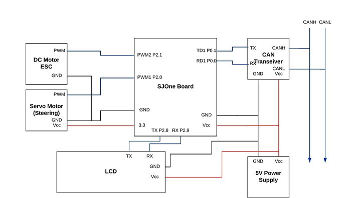
The car battery accepts compatible Ni-MH batteries. The battery powers the ESC unit, which in turn drives the motor and also powers the steering servo. The SJ One board, ESC unit and steering servo should share a common ground in order for the PWM signals to have the same reference voltage. The CAN transceiver uses the 5V power supply and GND, as well as the P0.0 (CAN RX) and P0.1 (CAN TX) of the SJ One Board. P2.0 (PWM1) and P2.1 (PWM2) controls the steering and motor respectively. This is done by sending out PWM signals from the SJ One board that change the width of a 20ms period waveform. 1ms width represents a 0% duty cycle, 1.5ms width represents a 50% duty cycle, and 2ms width represents a 100% duty cycle.
| Node A Source | Node A Pin | Node B Source | Node B Pin | Description |
|---|---|---|---|---|
| 3.3V Power Supply | 3.3V | SJOne Board | 3V3 | SJOne Power |
| 3.3V Power Supply | GND | SJOne Board | GND | SJOne Ground |
| CAN Transceiver | CAN Tx | SJOne Board | P0.1 (Tx) | SJOne - CAN Tx |
| CAN Transceiver | CAN Rx | SJOne Board | P0.0 (Rx) | SJOne - CAN Rx |
| CAN Transceiver | 5V | 5V Power Supply | 5V | SJOne - CAN Power |
| CAN Transceiver | Ground | 5V Power Supply | GND | SJOne - CAN Ground |
| CAN Transceiver | CANL | CAN BUS | CANL | CANL to CAN BUS |
| CAN Transceiver | CANR | CAN BUS | CANR | CANR to CAN BUS |
| Steering Servo | PWM Port | SJOne Board | P2.0 PWM | Steering Control |
| Steering Servo | Ground | SJOne Board | GND | Common ground for reference voltage |
| ESC/Motor | PWM Port | SJOne Board | P2.1 PWM | Motor Control |
| ESC/Motor | Ground | SJOne Board | GND | Common ground for reference voltage |
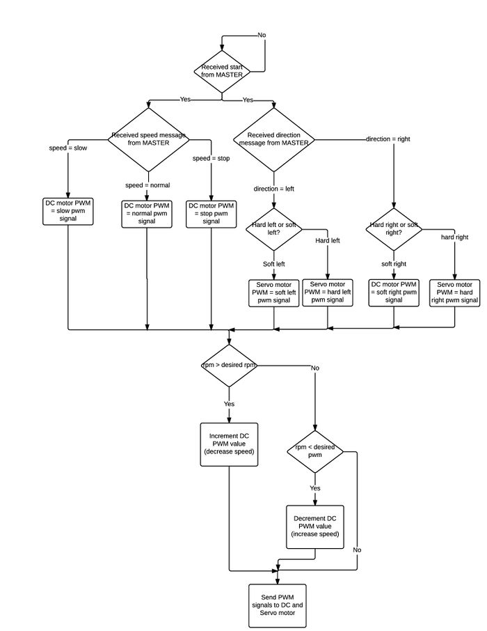
Software Flow Diagram
DC Motor
|
A DC motor converts direct current electrical power into mechanical power. The most common types rely on the forces produced by magnetic fields. Pulse width modulation (PWM) is used to control the motor. One advantage is that the power loss in the switching transistor is small because the transistor is either fully “ON” or fully “OFF”. As a result the switching transistor has a much reduced power dissipation giving it a linear type of control which results in better speed stability. The RC Car came with the motor that needed 7.4V of power supply to work. The motor has the power to run the car at a maximum speed of the 35mph.DC motor is controlled with the help of three wires coming out of the ESC. These wires are VCC, GND and Speed control. The VCC line is not used as required voltage is directly given to the motor through a battery, via ESC. The GND line and Speed control lines are connected to the ground and PWM pin of SJOne board.The DC motor was driven using pwm2 i.e. pin P2.1 of the SJOne board. In-built PWM generation function was used. It requires two parameters, one is pin being used and the other being the frequency. |
File:BLDC.gif |
| ESC Wire Pins | SJOne Board Pins |
|---|---|
| Vcc | - |
| GND | GND |
| Speed Control | P2.1 |
Servo Motor
|
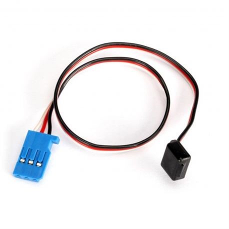
The RC Car came with a digital servo motor. The motor works without ESC. The motor is controlled by giving PWM signal from the SJOne board. |
Servo Motor |
|
Servo motor is controlled with the help of three wires coming out of the servo motor. The wires are VCC, GND and Direction control. The VCC is connected to the 3.3v. GND and direction control are connected to the ground and pwm pins of SJOne board.
Servo Motor Pin Connections We control the Servo motor using pwm1 i.e. pin P2.0 of the SJOne board. We configure the PWM pin using an in-build function which requires two parameters, one is the pin that we are using and the other is the frequency of the pwm. To set the duty cycle, in-build set function is used in which we are passing the duty cycle at which we want servo motor to work. |
Speed Feedback Encoder
The speed feedback is simply an rpm meter. It consists of a Hall Effect magnetic sensor with a set of magnets. The magnets are attached to the inner surface of the wheels and the sensor is connected to the end of the shaft connecting the wheel. Whenever the magnet comes near the sensor, a high signal is generated from the sensor and given to the GPIO port of the SJOne board, which is made as positive edge triggered. The interrupt handler would then increment a count which would give us revolutions per second if the above mentioned count is measured over one second (1Hz periodic callback function).
The next step would be to control speed with this calculated rpm. There are two conditions that need to be checked. One is the speed that the MASTER controller is sending (stop, slow, normal or fast) and another is the rpm. Each of the speeds would have a desired rpm and the calculated rpm is compared to the desired rpm and the final PWM signal to the DC motor is incremented or decremented depending on that. A scenario for this usage would be when the car encounters an upward ramp and the car would slow down while climbing to that. The algorithm would check and sense that the rpm has reduced and would modify PWM for DC to increase power and hence the rpm of car is kept at the desired range.
Liquid Crystal Display
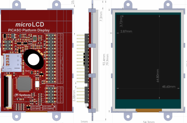
IO is the mode of interaction between user and car peripherals. It includes touch screen GLCD and headlights. LCD displays the car status while the touch screen allows the user to shift between various modes. The touch screen GLCD uLCD32PTU has the following features Low-cost 3.2" LCD-TFT display graphics user interface solution. 240 x 320 VGA resolution, RGB 65K true to life colours, TFT screen with Integrated 4-Wire Resistive Touch Panel. Easy 5 pin interface to any host device: VCC, TX, RX, GND, RESET Powered by 4D-Labs PICASO processor. 2 x Asynchronous hardware serial ports (COM0, COM1), TTL interface, with 300 to 600K baud. On-board micro-SD memory card adaptor for multimedia storage and data logging purposes. HC memory card support is also available for cards larger than 4GB. 4.0V to 5.5V range operation (single supply).
The LCD is used to display vital parameters such as
- Speed
- Obstacle proximity
- GPS co-ordinates
- Current and heading compass zone
Software Design
Show your software design. For example, if you are designing an MP3 Player, show the tasks that you are using, and what they are doing at a high level. Do not show the details of the code. For example, do not show exact code, but you may show psuedocode and fragments of code. Keep in mind that you are showing DESIGN of your software, not the inner workings of it.
Implementation
This section includes implementation, but again, not the details, just the high level. For example, you can list the steps it takes to communicate over a sensor, or the steps needed to write a page of memory onto SPI Flash. You can include sub-sections for each of your component implementation.
Testing & Technical Challenges
Describe the challenges of your project. What advise would you give yourself or someone else if your project can be started from scratch again? Make a smooth transition to testing section and described what it took to test your project.
Geographical Controller
Team Members & Responsibilities
- Ankit Gandhi
Schedule
| SI No. | Start Date | End Date | Task | Status | Actual Completion Date |
|---|---|---|---|---|---|
| 1 | 09/28/2016 | 10/4/2016 |
|
Complete | 10/6/2016 |
| 3 | 10/5/2016 | 10/11/2016 |
|
Complete | 10/10/2016 |
| 4 | 10/12/2016 | 10/18/2016 |
|
Complete | |
| 5 | 10/19/2016 | 10/25/2016 |
|
Complete | |
| 6 | 10/26/2016 | 11/01/2016 |
|
Complete | |
| 7 | 11/02/2016 | 11/08/2016 |
|
Complete | |
| 8 | 11/09/2016 | 12/05/2016 |
|
Upcoming Task |
Design & Implementation
The design section can go over your hardware and software design. Organize this section using sub-sections that go over your design and implementation.
GPS Module
The breakout is built around the MTK3339 chipset, a no-nonsense, high-quality GPS module that can track up to 22 satellites on 66 channels
- -165 dBm sensitivity, 10 Hz updates, 66 channels
- 5V friendly design and only 20mA current draw
- RTC battery-compatible
- Internal patch antenna + u.FL connector for external active antenna
The Compass Module - HMC5883L
Compass module is based on Honeywell’s HMC5883L. When current flows through a wire, a magnetic field is created. This is the basic principle behind electromagnets. This is also the principle used to measure magnetic fields with a magnetometer. The direction of Earth's magnetic fields affects the flow of electrons in the sensor, and those changes in current can be measured and calculated to derive a compass heading.
The features of HMC5883L are:
- Simple I2C interface
- 2.16-3.6VDC supply range
- Low current draw
- 5 milli-gauss resolution
Hardware Design
Discuss your hardware design here. Show detailed schematics, and the interface here.
Hardware Interface
In this section, you can describe how your hardware communicates, such as which BUSes used. You can discuss your driver implementation here, such that the Software Design section is isolated to talk about high level workings rather than inner working of your project.
Software Design
| Task Name | Purpose |
|---|---|
| Periodic 1Hz Callback | Receive Checkpoint from Master. |
| Periodic 10Hz Callback | Send GPS data over CAN BUS
Send IMU heading,bearing,speed and distance data over CAN Bus |
- Initialization
1. GPS module is interfaced using UART. UART is initialize using the most common configuration 9600/8-N-1(9600 baudrate, 8 databits, no (N) parity bit, and one (1) stop bit.
 void geotaskInit()
 {
   gpsUart.init(GPS_BAUD_RATE,rx_q,tx_q);   // Initialize UART for GPS
   LSM_MAG.init();                          // Initialize LSM303 Magnetometer
   LSM_ACCL.init();                         // Initialize LSM303 Accelerometer
 }
- GPS module is programmed to send GPS data at 10Hz. Interrupt Handler continuously receives these data and stores in the queue.
Periodically (10Hz) calling the getChar function gives a complete NMEA string.
// Following string is used to set NMEA output sentence, we are using GPRMC for this project
char dataTobeSenttoGPS[] = "$PMTK314,0,1,0,0,0,0,0,0,0,0,0,0,0,0,0,0,0,0,0*29\r\n";
char dataTobeSenttoGPS_1[] =  "$PMTK220,100*2F\r\n";
After sending this, we will be getting GPS string after every 10Hz, which is read by interrupt handler.
  bool geoTask::readGpsData()
  {
       int i=0;
       char c=0;
       while(gpsUart.getChar(&c, 0))
       {
               if ('\r' != c && '\n' != c)
               {
                   rxBuff[i++] = c;
               }
               if('\n' == c )
               {
                   break;
               }
       }
       rxBuff[i++] = '\0';
       strncpy(gpsStr,rxBuff,sizeof(rxBuff));
       parseGpsData(gpsStr);
       return true;
  }
- Sending data over CAN bus: In GeoController, we are using can1 for transmit and receive can messages. Latitude and longitude values are getting updated by GPS task using global structure. 'CAN send' function which is getting called every 100hz is using memcpy function to copy the structure data to CAN message and send over can bus.
Implementation
This section includes implementation, but again, not the details, just the high level. For example, you can list the steps it takes to communicate over a sensor, or the steps needed to write a page of memory onto SPI Flash. You can include sub-sections for each of your component implementation.
Testing & Technical Challenges
1. Compass Calibration
Communication Bridge Controller
Team Members & Responsibilities
- Bharat Khanna
- Shantanu Vashishtha
Schedule
| SI No. | Start Date | End Date | Task | Status | Actual Completion Date |
|---|---|---|---|---|---|
| 1 | 09/20/2016 | 09/27/2016 |
|
Complete | 09/27/2016 |
| 2 | 09/28/2016 | 10/4/2016 |
|
Complete | 10/9/2016 |
| 3 | 10/5/2016 | 10/11/2016 |
|
Complete | 10/11/2016 |
| 4 | 10/12/2016 | 10/18/2016 |
|
Complete | 10/18/2016 |
| 5 | 10/19/2016 | 10/25/2016 |
|
Complete | 10/25/2016 |
| 6 | 10/26/2016 | 11/08/2016 |
|
Complete | 11/08/2016 |
| 7 | 11/9/2016 | 11/20/2016 |
|
Complete | 11/20/2016 |
| 8 | 11/21/2016 | 12/05/2016 |
|
In Progress |
Design & Implementation
The design section can go over your hardware and software design. Organize this section using sub-sections that go over your design and implementation.
Bluetooth Module
RN42XV is built around Microchip's RN42 low power Bluetooth module. Some features of this module are as follows
- Based on the popular 2 x 10 (2mm) socket footprint.
- Voltage range: (3-3.6)Volts
- Current range: 26 μA sleep, 3 mA connected, 30 mA transmit.
- UART data connection interface.
- Sustained data rates: 240 Kbps (slave), 300 Kbps (master)
- Transmission range up to 60 feet (20 m) distance, +4 dBm output transmitter, -80 dBm typical receive sensitivity.
- FHSS/GFSK modulation, 79 channels at 1-MHz intervals.
Hardware Design
The interface between Bluetooth module and controller is as shown in figHardware Interface
In this section, you can describe how your hardware communicates, such as which BUSes used. You can discuss your driver implementation here, such that the Software Design section is isolated to talk about high level workings rather than inner working of your project.
Software Design
Show your software design. For example, if you are designing an MP3 Player, show the tasks that you are using, and what they are doing at a high level. Do not show the details of the code. For example, do not show exact code, but you may show psuedocode and fragments of code. Keep in mind that you are showing DESIGN of your software, not the inner workings of it.
Implementation
This section includes implementation, but again, not the details, just the high level. For example, you can list the steps it takes to communicate over a sensor, or the steps needed to write a page of memory onto SPI Flash. You can include sub-sections for each of your component implementation.
Testing & Technical Challenges
Describe the challenges of your project. What advise would you give yourself or someone else if your project can be started from scratch again? Make a smooth transition to testing section and described what it took to test your project.
Master Controller
Team Members & Responsibilities
- Aajna Karki
- Spoorthi Mysore Shivakumar
Schedule
| SI No. | Start Date | End Date | Task | Status | Actual Completion Date |
|---|---|---|---|---|---|
| 1 | 09/26/2016 | 10/05/2016 |
|
Complete | 10/05/2016 |
| 2 | 10/06/2016 | 10/18/2016 |
|
Complete | 10/18/2016 |
| 3 | 10/19/2016 | 10/25/2016 |
|
Complete | 10/25/2016 |
| 4 | 10/26/2016 | 11/07/2016 |
|
Complete | 11/07/2016 |
| 5 | 11/08/2016 | 11/15/2016 |
|
Complete | 11/20/2016 |
| 6 | 11/16/2016 | 11/29/2016 |
|
In Progress | |
| 7 | 11/29/2016 | 12/06/2016 |
|
Upcoming Task | |
| 8 | 12/06/2016 | 12/15/2016 |
|
Upcoming Task |
Design & Implementation
The design section can go over your hardware and software design. Organize this section using sub-sections that go over your design and implementation.
Hardware Design
Discuss your hardware design here. Show detailed schematics, and the interface here.
Hardware Interface
In this section, you can describe how your hardware communicates, such as which BUSes used. You can discuss your driver implementation here, such that the Software Design section is isolated to talk about high level workings rather than inner working of your project.
Software Design
Implementation
This section includes implementation, but again, not the details, just the high level. For example, you can list the steps it takes to communicate over a sensor, or the steps needed to write a page of memory onto SPI Flash. You can include sub-sections for each of your component implementation.
Testing & Technical Challenges
Describe the challenges of your project. What advise would you give yourself or someone else if your project can be started from scratch again? Make a smooth transition to testing section and described what it took to test your project.
My Issue #1
Discuss the issue and resolution.
Conclusion
Conclude your project here. You can recap your testing and problems. You should address the "so what" part here to indicate what you ultimately learnt from this project. How has this project increased your knowledge?
Project Video
Upload a video of your project and post the link here.
Project Source Code
References
Acknowledgement
This project has been an amazing learning experience for the whole team. The knowledge we take from here is immense. We are grateful to our Professor Preetpal Kang for his guidance and efforts towards making our learning commendable. Also, we would like to extend our sincere thanks to the ISA team for their continuous support. Here is a special mention to the Kasper team for all their meticulous and diligent efforts towards making this project a reality.
References Used
List any references used in project.
Appendix
You can list the references you used.
