F16: Titans
Contents
- 1 Project Title
- 2 Abstract
- 3 Objectives & Introduction
- 4 Track Progress in KanBan
- 5 Team Members & Responsibilities
- 6 Project Schedule
- 7 Parts List & Cost
- 8 Sensor Controller
- 9 Motor & I/O Controller
- 10 Geographical Controller
- 11 Communication Bridge Controller
- 12 Central Controller
- 13 Conclusion
- 14 References
Project Title
Abstract
This section should be a couple lines to describe what your project does.
Objectives & Introduction
Show list of your objectives. This section includes the high level details of your project. You can write about the various sensors or peripherals you used to get your project completed.
Track Progress in KanBan
Team Members & Responsibilities
- Master Controller
- Haroldo Filho
- Urvashi Agrawal
- Motor Controller
- Sant Prakash Soy
- Saketh Sai Narayana
- GPS/Compass Module
- Yang Thao
- Daamanmeet Paul
- Sensors
- Kayalvizhi Rajagopal
- Communication Bridge/Android App
- Parth Pachchigar
- Purvil Kamdar
Project Schedule
| Week# | Start Date | End Date | Task | Status |
|---|---|---|---|---|
| 1 | 09/13/2016 | 09/20/2016 | Order Components and work distribution | Completed |
| 2 | 09/21/2016 | 09/27/2016 | Set up git and wiki page | Completed |
| 3 | 09/28/2016 | 10/04/2016 | Receive Components and distribute to group members | Completed |
| 4 | 10/05/2016 | 10/11/2016 | Agree on control system architecture, assign CAN node priorities and decide on communication paradigm between Master and Nodes. Prep for prototype. | In Process |
| 5 | 10/12/2016 | 10/17/2016 | Testing week for all nodes. Goal is for each node to have a basic interface to their sensors and actuators in place, where they are able to read data and manipulate control signals. For instance: sensors node should be reading distance, motors node should be able to generate motor speed control signals. | Not Started |
| 6 | 10/18/2016 | 10/24/2016 | Interface all nodes over Canbus and coordinate order and status message transfers between Master and Nodes. | Not Started |
| 7 | 10/25/2016 | 10/31/2016 | Integrate all hardware to the RC car, including power supplies from batteries. Test self powered prototype with the goal of controlling forward, reverse, left and right from the phone app. Test & fix basic integration bugs. | Not Started |
| 8 | 11/1/2016 | 11/7/2016 | Continue with hardware/software development & integration and complete first prototype of the collision avoidance feature. | Not Started |
| 9 | 11/8/2016 | 11/14/2016 | Integrate GPS coordinates from Android app into Master Node for autonomous feature. | Not Started |
| 10 | 11/15/2016 | 11/21/2016 | Integrate all nodes into one. Start testing car's autonomous driving capabilities with path following from GPS waypoints from Android app. | Not Started |
| 11 | 11/22/2016 | 11/28/2016 | Autonomous driving should be working by now. Focus on improving car's performance. Tweak all nodes to better performance, and fix last minutes bugs. | Not Started |
| 12 | 11/29/2016 | Presentation date | Final touches to improve overall vehicle's robustness. Self-fixing nodes, reduce/eliminate unexpected behaviors and crashes. | Not Started |
Parts List & Cost
| Item# | Part Desciption | Vendor | Qty | Cost |
|---|---|---|---|---|
| 1 | RC Car - Traxxas 1/10 Slash 2WD | Amazon | 1 | $189.95 |
| 2 | Traxxas 2872X 5000mAh 11.1V 3S 25C LiPo Battery | Amazon | 1 | $56.99 |
| 3 | Traxxas 7600mAh 7.4V 2-Cell 25C LiPo Battery | Amazon | 1 | $70.99 |
| 4 | Traxxas 2970 EZ-Peak Plus 4-Amp NiMH/LiPo Fast Charger | Amazon | 1 | $35.99 |
| 5 | Bluetooth 4.0 BLE Bee Module (Dual Mode) | Robotshop | 1 | $19.50 |
| 6 | Serial Graphics LCD (128x64) | Sparkfun | 1 | $41.55 |
| 7 | LV Maxsonar EZ0 Ultrasonic sensors | Robotshop | 5 | $124.75 |
Sensor Controller
Schedule
| Week# | Start Date | End Date | Task | Status |
|---|---|---|---|---|
| 1 | 09/13/2016 | 09/20/2016 | Investigate on what type of sensors are needed and the model of sensors to use and order them. | Completed |
| 2 | 09/21/2016 | 09/27/2016 | Interface one sonic sensor and test with different environment conditions. | Completed |
| 3 | 09/28/2016 | 10/11/2016 | Interface all the front sensors. Stress test the sensors & log the values on SD card. Design a filter based on the log so that reliable readings are sent to the master. | Completed |
| 4 | 10/12/2016 | 10/24/2016 | Integrate sensors with motors and test the sensor values while car is on the move. | In Process |
| 5 | 10/12/2016 | 10/24/2016 | Mount the sensors & sensor controller on the car and integrate it with rest of the controllers. | Not Started |
| 6 | 10/24/2016 | 11/07/2016 | Tune & optimize the sensor filter logic and the sensor mount as required. | Not Started |
Design & Implementation
The design section can go over your hardware and software design. Organize this section using sub-sections that go over your design and implementation.
Hardware Design
Discuss your hardware design here. Show detailed schematics, and the interface here.
Hardware Interface
In this section, you can describe how your hardware communicates, such as which BUSes used. You can discuss your driver implementation here, such that the Software Design section is isolated to talk about high level workings rather than inner working of your project.
Software Design
Show your software design. For example, if you are designing an MP3 Player, show the tasks that you are using, and what they are doing at a high level. Do not show the details of the code. For example, do not show exact code, but you may show psuedocode and fragments of code. Keep in mind that you are showing DESIGN of your software, not the inner workings of it.
Implementation
This section includes implementation, but again, not the details, just the high level. For example, you can list the steps it takes to communicate over a sensor, or the steps needed to write a page of memory onto SPI Flash. You can include sub-sections for each of your component implementation.
Testing & Technical Challenges
Describe the challenges of your project. What advise would you give yourself or someone else if your project can be started from scratch again? Make a smooth transition to testing section and described what it took to test your project.
Motor & I/O Controller
Schedule
| Week# | Start Date | End Date | Task | Status | |
|---|---|---|---|---|---|
| 1 | 09/13/2016 | 09/20/2016 | Research on components requirement based on past projects. | Completed | |
| 2 | 09/13/2016 | 09/20/2016 | Order motor controller related components: Traxxas RPM sensor, (Servo motor, DC motor and ESC)Included in traxxas RC car. | Completed | |
| 3 | 09/13/2016 | 09/20/2016 | Reverse engineering Traxxas ESC, signal receiver, and signal transmitter to learn about basic functionality of the car. | Completed | |
| 4 | 09/13/2016 | 09/20/2016 | * Experiment and Research on voltage requirements for Servo and DC motor. | * Experiment and Research on PWM frequency requierments for DC and Servo motor | Completed |
Design & Implementation
The design section can go over your hardware and software design. Organize this section using sub-sections that go over your design and implementation.
Hardware Design
Discuss your hardware design here. Show detailed schematics, and the interface here.
Hardware Interface
In this section, you can describe how your hardware communicates, such as which BUSes used. You can discuss your driver implementation here, such that the Software Design section is isolated to talk about high level workings rather than inner working of your project.
Software Design
Show your software design. For example, if you are designing an MP3 Player, show the tasks that you are using, and what they are doing at a high level. Do not show the details of the code. For example, do not show exact code, but you may show psuedocode and fragments of code. Keep in mind that you are showing DESIGN of your software, not the inner workings of it.
Implementation
This section includes implementation, but again, not the details, just the high level. For example, you can list the steps it takes to communicate over a sensor, or the steps needed to write a page of memory onto SPI Flash. You can include sub-sections for each of your component implementation.
Testing & Technical Challenges
Describe the challenges of your project. What advise would you give yourself or someone else if your project can be started from scratch again? Make a smooth transition to testing section and described what it took to test your project.
Geographical Controller
Design & Implementation
The design section can go over your hardware and software design. Organize this section using sub-sections that go over your design and implementation.
Hardware Design
Discuss your hardware design here. Show detailed schematics, and the interface here.
Hardware Interface
In this section, you can describe how your hardware communicates, such as which BUSes used. You can discuss your driver implementation here, such that the Software Design section is isolated to talk about high level workings rather than inner working of your project.

|
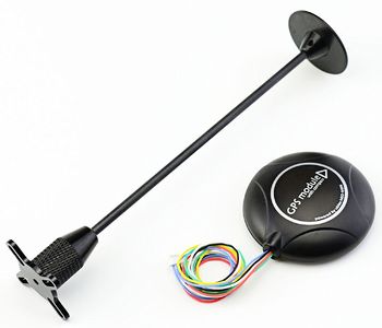
GPS Module: Readytosky Ublox NEO-M8N This GPS module uses UART serial communication interface. The refresh rate ranges from 1Hz up to 10Hz with a default baud rate of 9600bps. This module is an updated version to the Ublox NEO-M7N which brings improved accuracy of up to 0.9 meters using its build in antenna. Specifications:
|
|
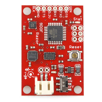
Razor IMU - 9 Degrees of Freedom The 9DOF Razor IMU incorporates three sensors - an ITG-3200 (MEMS triple-axis gyro), ADXL345 (triple-axis accelerometer), and HMC5883L (triple-axis magnetometer) - to give you nine degrees of inertial measurement. The outputs of all sensors are processed by an on-board ATmega328 and output over a serial interface. |
Software Design
Show your software design. For example, if you are designing an MP3 Player, show the tasks that you are using, and what they are doing at a high level. Do not show the details of the code. For example, do not show exact code, but you may show psuedocode and fragments of code. Keep in mind that you are showing DESIGN of your software, not the inner workings of it.
Implementation
This section includes implementation, but again, not the details, just the high level. For example, you can list the steps it takes to communicate over a sensor, or the steps needed to write a page of memory onto SPI Flash. You can include sub-sections for each of your component implementation.
Testing & Technical Challenges
Describe the challenges of your project. What advise would you give yourself or someone else if your project can be started from scratch again? Make a smooth transition to testing section and described what it took to test your project.
Communication Bridge Controller
Design & Implementation
The design section can go over your hardware and software design. Organize this section using sub-sections that go over your design and implementation.
Hardware Design
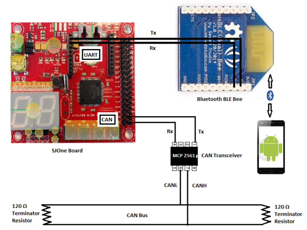
Here is the hardware block diagram of Communication Bridge Controller.
Here is the hardware block diagram of Communication Bridge Controller. Here is the hardware block diagram of Communication Bridge Controller. Here is the hardware block diagram of Communication Bridge Controller.
Hardware Interface
In this section, you can describe how your hardware communicates, such as which BUSes used. You can discuss your driver implementation here, such that the Software Design section is isolated to talk about high level workings rather than inner working of your project.
Software Design
Show your software design. For example, if you are designing an MP3 Player, show the tasks that you are using, and what they are doing at a high level. Do not show the details of the code. For example, do not show exact code, but you may show psuedocode and fragments of code. Keep in mind that you are showing DESIGN of your software, not the inner workings of it.
Implementation
This section includes implementation, but again, not the details, just the high level. For example, you can list the steps it takes to communicate over a sensor, or the steps needed to write a page of memory onto SPI Flash. You can include sub-sections for each of your component implementation.
Testing & Technical Challenges
Describe the challenges of your project. What advise would you give yourself or someone else if your project can be started from scratch again? Make a smooth transition to testing section and described what it took to test your project.
Central Controller
Schedule
| Week# | Start Date | End Date | Task | Status |
|---|---|---|---|---|
| 1 | 09/20/2016 | 09/30/2016 | Decide on the CAN ids and the priorities of the CAN messaged for various nodes.Design the barebones basic functionality of the algorithm. Create a skeleton code. | Completed |
| 2 | 09/30/2016 | 10/10/2016 | Set up CAN communication between the sensor and the master. Test for correct data transmission. Design the algorithm for the data processing received by the master. | In Process |
| 3 | 10/10/2016 | 10/20/2016 | Extend the algorithm to control the motors along with the obstacle information received from the sensors. Establish CAN communication between the master and the motors. | In Process |
| 4 | 10/20/2016 | 10/30/2016 | Obtain the data from the GPS and process the data to design the algorithm for navigation. Design and implement the kill switch to avoid the car from crashing | In Process |
| 5 | 10/30/2016 | 11/10/2016 | Integrate all the modules and test for the functionality. Save the data received from various modules into a log file for debugging purpose. Include the headlights and the LCD on the car and display messages on them. | Not Started |
| 6 | 11/10/2016 | 11/20/2016 | Improvise the algorithm and carry out stress testing and integration testing. Work on the modifications required and test previous hardware additions to the car. | Not Started |
| 7 | 11/20/2016 | 12/15/2016 | Integration and testing. Work to improvise on the algorithms and make sure individual modules work. Addition of any extra features and software development. | Not Started |

