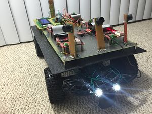
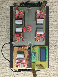
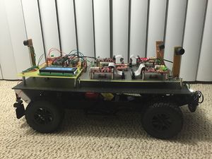
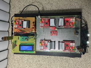
F15: ThunderBird
Contents
- 1 ThunderBird : Self Driving Car
- 2 Abstract
- 3 Objectives & Introduction
- 4 Schedule
- 5 Parts List & Cost
- 6 Design & Implementation
- 7 Sensor Controller
- 8 Motor and I/O Controllers
- 9 GPS Controller
- 10 Master Controller
- 11 Bluetooth Control and Android application
- 12 Testing & Technical Challenges
- 13 Conclusion
- 14 References
ThunderBird : Self Driving Car
Abstract
ThunderBird is a 1/10 2 WD electric short self-driving truck. The truck is equipped with sensors to detect obstacles, GPS for getting directions, Compass for the truck's orientation, Bluetooth for communicating with the android device and LCD for displaying the sensor values, velocity of the truck and current heading on screen. The modules are interfaced using 5 SJ One boards which features a Cortex-M3 LPC1758. CAN bus is used for communicating between the modules. Android device is used to send start message and enter the destination coordinates through Bluetooth. Based on the GPS co-ordinates master directs the motor in respective direction and if the sensors detect obstacles, it signals the motors to drive the car accordingly. Based on GPS co-ordinates and sensor values Master directs the truck until destination is reached.
Objectives & Introduction
Objective
Objective of this project is to be able to work as a team of ten members to develop an Autonomous self driving Car. which gives us the real time work experience as the team of ten members has to be divided into subteams and work on individual modules(Sensors controller, Motor and I/O controller, GPS controller, Android controller and Master controller ) by collaborating with other sub team members for communication between the modules.
Main goal of this project is to understand how CAN protocol works and its architecture in detail, as all controllers of the system communicate through CAN bus.
Team Members & Responsibilities
- Master Controller and Android application
- Sravani Aitha
- Vishnu Vardhana Reddy Mandalapu
- James Sushanth Anandraj
- Athavan Kanagasabapathy
- Sravani Aitha
- Motors and I/O
- Dheeraj Dake
- Akhil Bhargav Josyabhatla
- Dheeraj Dake
- Sensors
- Nitesh Jain
- Rajashree Kambli
- GPS
- Rishit Borad
- Ravi Vanjara
Introduction
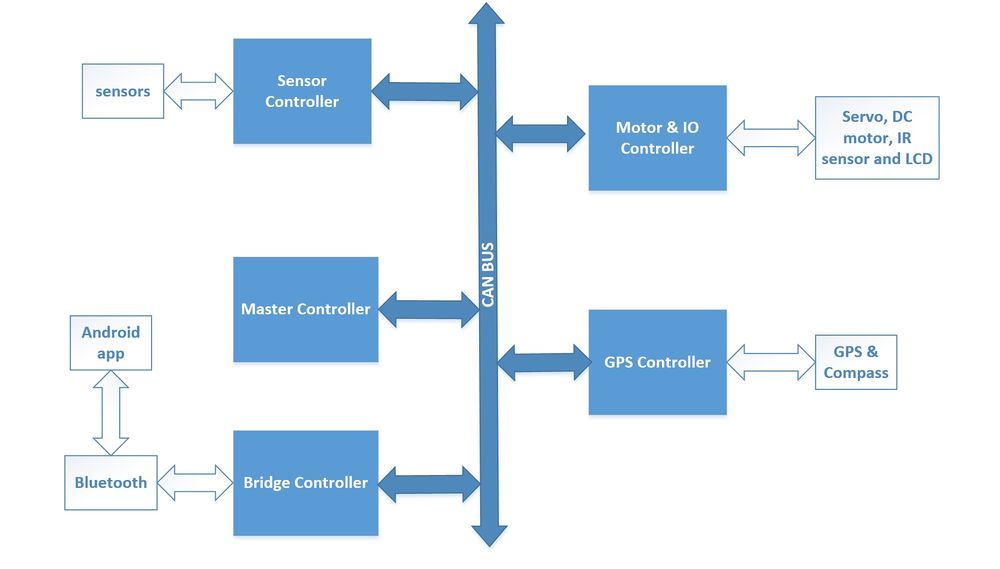
Our Autonoumous self-driving car is designed in a way that it has five controllers to deal with different functions of the car and these controllers communicate through CAN bus, below is the description for various controllers.
- Bridge Controller : Bridge controller receives the start, stop messages and check points from the android application and it sends the start and stop messages over CAN bus in order to start and stop the car.
- Motors and I/O Controller : Motor controller receives the steer and direction information from the master controller and navigates the car in required direction.
- Sensors Controller : There are four sensors mounted on the car, three in front and one on rear, sensor controller update the motor with obstacle information by sending the updates from the sensors.
- GPS Controller : GPS controller sends the updated direction and the distance to the destination.
- Master Controller : Master controller collaborate the messages from Brdidge, sensor and GPS controllers and directs the motor in required direction.
Overall Algorithm
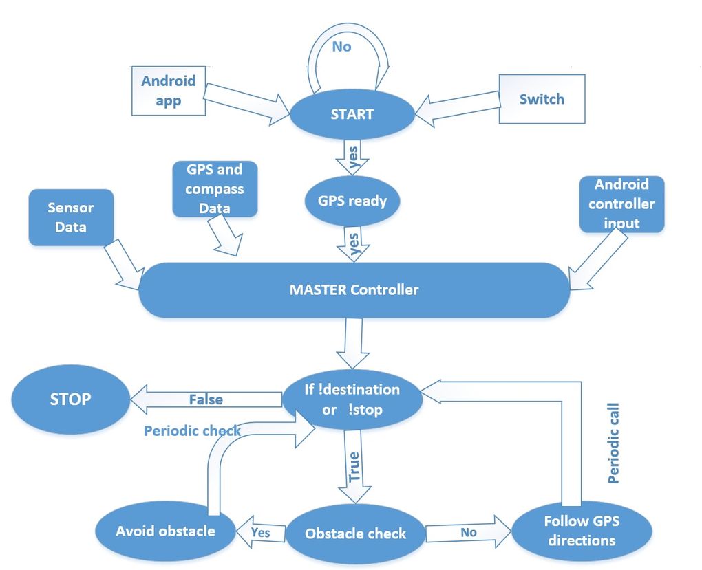
   1. Android/Bridge controller sends the start command to master controller as soon it receives start from android app.
   2. GPS controller sends the current location to Bridge and Bridge relays the current co-ordinates to android app.
   3. Android application sends the required destination to the Bridge controller and Bridge controller sends the information to GPS controller.
   4. Based on the current location and destination, GPS+Compass controller decides the required direction for the car to navigate and sends it to Master controller.
   5. Master starts listening to sensor data from sensor controller, required direction from GPS+compass controller and it also keeps listening to android controller for any stop
      message.
   6. As soon as Master receives GPS start command, Master controller starts calculating the right direction for the car to navigate.
   7. Sensor Controller keeps sending sensor values on the bus and  Motor+IO controller, Bridge controller.
   8. Bridge controller sends the sensor values to android app for the displays, android app keeps updating its sensor values as soon as receives an update from bridge controller.
   9. Motor+IO controller keeps listening to the data from GPS+Compass controller for the heading direction and updates the LCD display accordingly.
   10. Motor+IO controller updates all the sensor values on the LCD display as soon as it receives the update from sensor controller.
   11. Master decides the right direction for the car based on sensor values and GPS-co ordinates, sends the message to Motor to move the vehicle in decided direction.
   12. Motor listens to the direction from Master controller and directs the car accordingly. .
   13. Step 4 to 12 continue until the Master receives stop command from Android controller or destination reached message from GPS Controller.
   14. As soon as Master receives stop message or destination reached command, Master sends stop message to Motor Controller.
   15. Motor controller stops the car as soon as it receives stop command from Master controller.
Controllers
Schedule
Team Schedule
| Sl.No | Start Date | End Date | Task | Status | Actual Completion Date |
|---|---|---|---|---|---|
| 1 | 09/22/2015 | 09/29/2015 | Order RC Car | Completed | 09/26/2015 |
| 2 | 09/30/2014 | 10/6/2015 | Ordered components | Completed | 10/04/2015 |
| 3 | 10/07/2015 | 10/13/2015 | Study about the modules and the RC car | Completed | 10/13/15 |
| 4 | 10/14/2015 | 10/20/2015 | Test motors using PWM | Completed | 10/16/15 |
| 5 | 10/21/2015 | 10/28/2015 | Interface sensor modules | Completed | 10/26/15 |
| 6 | 10/29/2015 | 11/05/2015 | Interface GPS and compass | Completed | 11/6/15 |
| 7 | 11/12/2015 | 11/19/2015 | Interface LCD | Completed | 11/28/15 |
| 8 | 11/20/2015 | 11/27/2015 | Interface modules over CAN bus | Completed | 11/26/15 |
| 9 | 11/28/2015 | 12/05/2015 | Integrating modules | Completed | 12/8/15 |
| 10 | 12/6/2015 | 12/13/2015 | Testing | Completed | 12/15/15 |
| 11 | 12/14/2015 | 12/19/2015 | More Testing | Completed | 12/18/15 |
Motor and I/O Schedule
| Sl. No | Start Date | End Date | Task | Status | Actual Completion Date |
|---|---|---|---|---|---|
| 1 | 10/6/2015 | 10/13/2015 | Determining the ESC initialization sequence | Completed | 10/11/15 |
| 2 | 10/13/2015 | 10/20/2015 | Testing the Servo and DC motor using SJ One board PWM's | Completed | 10/16/2015 |
| 3 | 10/20/2015 | 10/27/2015 | Design motor control using messages from the CAN bus | Completed | 10/27/15 |
| 4 | 10/27/2015 | 11/3/2015 | Implement code to accept messages from other modules over CAN bus and display it on the LCD | Completed | 11/28/15 |
| 5 | 11/3/2015 | 11/10/2015 | Update motor speeds on the LCD in real time | Completed | 11/28/15 |
| 6 | 11/10/2015 | 11/17/2015 | Interface I/O and motor modules with master controller and establish communication | Completed | 11/28/15 |
| 7 | 11/17/2015 | 11/24/2015 | Fine turning motors for precise control | Completed | 11/24/15 |
| 8 | 11/24/2015 | 12/01/2015 | Fine tuning (buffer) | Completed | 12/2/15 |
| 9 | 12/01/2015 | 12/08/2015 | Testing and debugging | Completed | 12/10/15 |
Geographical Position Controller Schedule
| Sl. No | Start Date | End Date | Task | Status | Actual Completion Date |
|---|---|---|---|---|---|
| 1 | 10/6/2015 | 10/13/2015 | Research & order GPS module | Completed | 10/8/2015 |
| 2 | 10/13/2015 | 10/20/2015 | Interface GPS using I2C with SJOne board | Completed | 10/20/15 |
| 3 | 10/20/2015 | 10/27/2015 | Interface Compass with SJOne board | Completed | 10/27/15 |
| 4 | 10/27/2015 | 11/3/2015 | Calibrate Compass and GPS | Completed | 11/2/15 |
| 5 | 11/3/2015 | 11/10/2015 | Parse raw data and create meaningful data | Completed | 11/21/15 |
| 6 | 11/10/2015 | 11/17/2015 | Implement CAN communication with SJOne board | Completed | 11/19/15 |
| 7 | 11/17/2015 | 11/24/2015 | Test and debug GPS & Compass locally | Completed | 11/24/15 |
| 8 | 11/24/2015 | 12/01/2015 | Integrate GPS/Compass module with Master board | Completed | 12/2/15 |
| 9 | 12/01/2015 | 12/08/2015 | Implement routing algorithm for Car | Completed | 12/10/15 |
| 10 | 12/08/2015 | 12/15/2015 | Test and Debug GPS/Compass integration with master | Completed | 12/17/15 |
Sensor Controller Schedule
| Sl. No | Start Date | End Date | Task | Status | Actual Completion Date |
|---|---|---|---|---|---|
| 1 | 10/5/2015 | 10/11/2015 | Finalize and order the sensors | Completed | 10/11/2015 |
| 2 | 10/12/2015 | 10/18/2015 | Wire the sensors and write a sample test code to check the sensors. | Completed | 10/18/2015 |
| 3 | 10/19/2015 | 11/01/2015 | Transfer the sensor data to master controller via can bus. | Completed | 10/31/2015 |
| 4 | 11/2/2015 | 11/9/2015 | Implement and integrate the code for all the sensors. | Completed | 11/15/2015 |
| 5 | 11/2/2015 | 11/15/2015 | Test and Debug the integrated module. | Completed | 10/15/2015 |
| 6 | 11/16/2015 | 11/29/2015 | Collaborate with the other module teams to make sure that the sensors are in working condition. | Completed | 11/30/2015 |
| 7 | 11/30/2015 | 12/06/2015 | Test for stability of sensors and report. | Completed | 11/31/15 |
| 8 | 12/07/2015 | 12/13/2015 | Prepare for Demo. | Completed | 12/13/15 |
Master controller and android controller Schedule
| Sl. No | Start Date | End Date | Task | Status | Actual Completion Date |
|---|---|---|---|---|---|
| 1 | 10/6/2015 | 10/13/2015 | Car purchase ,dismantle and setup for project | Completed | 10/8/2015 |
| 2 | 10/13/2015 | 10/20/2015 | Can setup components purchase, Can bus design and soldering | Completed | 10/20/15 |
| 3 | 10/20/2015 | 10/27/2015 | Basic Can communication testing by sending and receiving data and can msg specification for all controllers and messages. | Completed | 10/27/15 |
| 4 | 10/27/2015 | 11/3/2015 | Development and implementation of Algorithm for driving car and obstacle avoidance. | Completed | 11/2/15 |
| 5 | 11/3/2015 | 11/10/2015 | Interface bt dongle with sjone board and android device and test with commands | Completed | 11/11/15 |
| 6 | 11/10/2015 | 11/17/2015 | Develop Android GUI and application to interact with car using bluetooth. Implement all necessary commands on sjone board for communication with android device. Interface with Motor and IO Controller. | Completed | 11/18/15 |
| 7 | 11/17/2015 | 11/24/2015 | Test and debug Master algorithm and Android interface locally and with Motor controller interfaced by providing predetermined directional commands. | Completed | 11/23/15 |
| 8 | 11/24/2015 | 12/01/2015 | Integrate Master Board with all boards and implement heartbeat protocol. | Completed | 11/2/15 |
| 9 | 12/01/2015 | 12/08/2015 | Test run 1 with all boards integrated and with all planned features developed. | Completed | 12/8/15 |
| 10 | 12/08/2015 | 12/15/2015 | Test run 2 after solving issues found in test run 1. | Completed | 12/17/15 |
Parts List & Cost
| S.R. | Description | Manufacturer | Part Number | Qty | Total Cost |
|---|---|---|---|---|---|
| 1 | SJOne Board | - | - | 5 | $400.00 |
| 2 | RC Car | Furry Arrma - 2 Wheel Drive - 1/10 | - | 1 | $185.00 |
| 3 | Ultrasonic Sensor | LV-MaxSonar - EZ1 | MB1010 | 5 | $140.00 |
| 4 | 1.8 Color TFT LCD display with MicroSD Card Breakout | Adafruit | ST7735R | 1 | $19.95 |
| 5 | SparkFun Venus GPS with SMA Connector | Sparkfun | GPS-11058 | 1 | $49.95 |
| 6 | Triple-axis Magnetometer (Compass) Board | Adafruit | HMC5883L | 1 | $9.95 |
| 7 | CAN Transceiver (Free Samples) | Microchip | MCP2551 | 6 | $0.00 |
| Total (Including Shipping and Taxes | ---- |
Design & Implementation
CAN 11-bit ID Format
| MSG | DST | SRC |
|---|---|---|
| 5 bits (11-6) | 3 bits (5-3) | 3 bits (2-0) |
Controller ID Table
| Controller ID | Controller Type |
|---|---|
| 0xA0 | Master Controller |
| NO TX | Motor Controller & I/O Controller |
| 0xB0 | GPS |
| 0xC8 | Sensor |
| 0x00 | Android Controller |
This DBC File has used to communicate between all controllers in RC Car.
VERSION ""
NS_ :
NS_DESC_
CM_
BA_DEF_
BA_
VAL_
CAT_DEF_
CAT_
FILTER
BA_DEF_DEF
EV_DATA_
ha
ENVVAR_DATA_
SGTYPE_
SGTYPE_VAL_
BA_DEF_SGTYPE_
BA_SGTYPE_
SIG_TYPE_REF_
VAL_TABLE_
SIG_GROUP_
SIG_VALTYPE_
SIGTYPE_VALTYPE_
BO_TX_BU_
BA_DEF_REL_
BA_REL_
BA_DEF_DEF_
REL_
BU_SG_REL_
BU_EV_REL_
BU_BO_REL_
SG_MUL_VAL_
BS_:
BU_: NOONE SENSOR DRIVER MOTOR GPS IO
BO_ 0xA0 HEARTBEAT: 1 DRIVER
SG_ DRIVER_HEARTBEAT_cmd : 0|8@1+ (1,0) [0|0] "" SENSOR,MOTOR,GPS
BO_ 0xA1 sensorback: 1 SENSOR
SG_ SENSOR_BACK_cmd : 0|8@1+ (1,0) [0|0] "" DRIVER,MOTOR,GPS,IO
BO_ 0x02 IOSTART: 1 IO
SG_ IOSTART_cmd : 0|8@1+ (1,0) [0|0] "" DRIVER
BO_ 0x01 IOSTOP: 1 IO
SG_ IOSTOP_cmd : 0|8@1+ (1,0) [0|0] "" DRIVER
BO_ 0x03 IOCHECKPOINTCOUNT: 1 IO
SG_ IOCOUNT_cmd : 0|8@1+ (1,0) [0|0] "" GPS,DRIVER
BO_ 0x05 GPSCHECKPOINTCOUNT: 1 GPS
SG_ GPSCOUNT_cmd : 0|8@1+ (1,0) [0|0] "" IO,DRIVER
BO_ 0x04 IOGPSCHECKPOINT: 8 IO
SG_ IOLATITUDE : 0|32@1+ (0.1,0) [0|0] "DEGREE" DRIVER,GPS
SG_ IOLONGTITUDE : 32|32@1+ (0.1,0) [0|0] "DEGREE" DRIVER,GPS
BO_ 0xB0 COMPASS: 4 GPS
SG_ COMPASS_direction : 0|8@1+ (1,0) [0|0] "DIRECTION" DRIVER,GPS,MOTOR
SG_ COMPASS_angle : 8|16@1- (1,0) [0|0] "DEGREE" DRIVER,GPS,MOTOR
BO_ 0xB1 GPS_longitude: 8 GPS
SG_ GPS_longitude_cur : 0|32@1+ (1,0) [0|0] "DEGREE" DRIVER,GPS,MOTOR
SG_ GPS_longitude_dst : 32|32@1+ (1,0) [0|0] "DEGREE" DRIVER,GPS,MOTOR
BO_ 0xB2 GPS_latitude: 8 GPS
SG_ GPS_latitude_cur : 0|32@1+ (1,0) [0|0] "DEGREE" DRIVER,GPS,MOTOR
SG_ GPS_latitude_dst : 32|32@1+ (1,0) [0|0] "DEGREE" DRIVER,GPS,MOTOR
BO_ 0xB3 GPS_heading: 8 GPS
SG_ GPS_heading_cur : 0|32@1+ (1,0) [0|0] "DEGREE" DRIVER,GPS,MOTOR
SG_ GPS_heading_dst : 32|32@1+ (1,0) [0|0] "DEGREE" DRIVER,GPS,MOTOR
BO_ 0xB4 GPS_dest_reached: 4 GPS
SG_ GPS_dest_reached : 0|32@1+ (1,0) [0|0] "" DRIVER,GPS,MOTOR
BO_ 200 SONARS: 6 SENSOR
SG_ SENSOR_SONARS_mux M : 0|4@1+ (1,0) [0|0] "" DRIVER,IO,MOTOR
SG_ SENSOR_SONARS_s1_fault : 4|1@1+ (1,0) [0|0] "" DRIVER,IO,MOTOR
SG_ SENSOR_SONARS_s2_fault : 5|1@1+ (1,0) [0|0] "" DRIVER,IO,MOTOR
SG_ SENSOR_SONARS_s3_fault : 6|1@1+ (1,0) [0|0] "" DRIVER,IO,MOTOR
SG_ SENSOR_SONARS_s4_fault : 7|1@1+ (1,0) [0|0] "" DRIVER,IO,MOTOR
SG_ SENSOR_SONARS_left m0 : 8|12@1+ (0.1,0) [0|400] "" DRIVER,IO,MOTOR
SG_ SENSOR_SONARS_middle m0 : 20|12@1+ (0.1,0) [0|0] "" DRIVER,IO,MOTOR
SG_ SENSOR_SONARS_right m0 : 32|12@1+ (0.1,0) [0|0] "" DRIVER,IO,MOTOR
SG_ SENSOR_SONARS_rear m0 : 44|12@1+ (0.1,0) [0|0] "" DRIVER,IO,MOTOR
SG_ SENSOR_SONARS_no_filt_left m1 : 8|12@1+ (0.1,0) [0|400] "" NOONE
SG_ SENSOR_SONARS_no_filt_middle m1 : 20|12@1+ (0.1,0) [0|400] "" NOONE
SG_ SENSOR_SONARS_no_filt_right m1 : 32|12@1+ (0.1,0) [0|400] "" NOONE
SG_ SENSOR_SONARS_no_filt_rear m1 : 44|12@1+ (0.1,0) [0|400] "" NOONE
BO_ 0X020 MOTOR_CMD: 3 DRIVER
SG_ MOTOR_CMD_steer : 0|8@1- (1,0) [0|0] "" MOTOR
SG_ MOTOR_CMD_drive : 8|8@1+ (1,0) [0|0] "" MOTOR
SG_ MOTOR_CMD_angle : 16|8@1+ (1,0) [0|0] "" MOTOR
CM_ BU_ NOONE "No node, used to indicate if it's a debug message going to no one"; CM_ BU_ DRIVER "The DRIVER controller driving the car"; CM_ BU_ SENSOR "The sensor controller of the car"; CM_ BU_ MOTOR "The motor controller of the car"; CM_ BO_ 0xA0 "Sync message used to synchronize the controllers";
BA_DEF_ "BusType" STRING ; BA_DEF_ SG_ "FieldType" STRING ; BA_DEF_ BO_ "GenMsgCycleTime" INT 0 0;
BA_DEF_DEF_ "BusType" "CAN"; BA_DEF_DEF_ "FieldType" "";
BA_ "GenMsgCycleTime" BO_ 0xA0 1000; BA_ "GenMsgCycleTime" BO_ 0x01 100; BA_ "GenMsgCycleTime" BO_ 0X020 100; BA_ "FieldType" SG_ 0xA0 DRIVER_HEARTBEAT_cmd "DRIVER_HEARTBEAT_cmd";
VAL_ 0xA0 DRIVER_HEARTBEAT_cmd 1 "DRIVER_HEARTBEAT_cmd_NOOP" 1 "DRIVER_HEARTBEAT_cmd_SYNC" 2 "DRIVER_HEARTBEAT_cmd_REBOOT";
Hardware Design
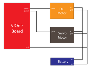
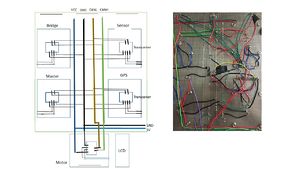 Fig 2.ThunderBird Hardware Diagram
The hardware was designed in a very clean and neat design with the help of 17 pin jumper cables matching the SJ-One board in order to save the space and avoid the multiple layers of wiring. Every hardware parts were built upon after careful consideration.
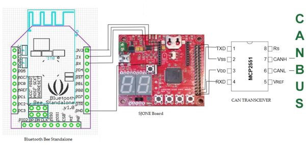
The CAN Controller used is MCP2551. It is a high speed transceiver which serves as boundary for all the SJ-One controllers which helps to communicate with each other. The operating speed of the bus is upto 1 megabits per second. The high and low signal acting as the output are protected internally against any short-circuits and sudden transitions in voltage level. The connection to SJ-One board is shown s per below diagram,
Hardware Interface
In this section, you can describe how your hardware communicates, such as which BUSes used. You can discuss your driver implementation here, such that the Software Design section is isolated to talk about high level workings rather than inner working of your project.
Software Design
Show your software design. For example, if you are designing an MP3 Player, show the tasks that you are using, and what they are doing at a high level. Do not show the details of the code. For example, do not show exact code, but you may show psuedocode and fragments of code. Keep in mind that you are showing DESIGN of your software, not the inner workings of it.
Implementation
Working Mechanism
Sensor Controller
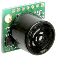
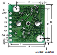
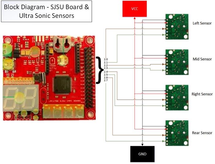
We have used four Maxbotix LV-EZ Ultrasonic Range Finder sensors (MB1010), three for front (left, right, mid) and one for the rear. These ultrasonic sensors are used to detect the obstacle which our car can encounter on its route. These sensors are connected to the SJOne board and the CAN bus and can work on 3.3V-5.0V.
The pin configuration for the sensor is as follows:
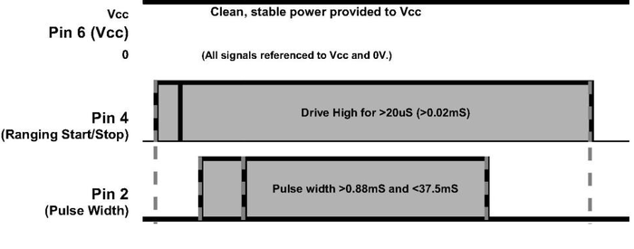
1) Pin 2-PW: This pin outputs a pulse width representation of range. The distance can be calculated using the scale factor of 147uS per inch.
2) Pin 4-RX: This pin is internally pulled high. The LV-MaxSonar-EZ will continually measure range and output if RX data is left unconnected or held high. If held low the sensor will stop ranging. Bring high for 20uS or more to command a range reading.
3) Pin 6-+5V: Vcc – Operates on 2.5V - 5.5V. Recommended current capability of 3mA for 5V, and 2mA for 3V.
4) Pin 7-GND: Return for the DC power supply. GND (& Vcc) must be ripple and noise free for best operation.
Sensor Hardware Design
250mS after power-up, the LV-MaxSonar-EZ is ready to accept the RX command. If the RX pin is left open or held high, the sensor will first run a calibration cycle (49mS), and then it will take a range reading (49mS). After the power up delay, the first reading will take an additional ~100mS. Subsequent readings will take 49mS. The LV-MaxSonar-EZ checks the RX pin at the end of every cycle. Range data can be acquired once every 49mS.
Each 49mS period starts by the RX being high or open, after which the LV-MaxSonar-EZ sends the transmit burst, after which the pulse width pin (PW) is set high. When a target is detected the PW pin is pulled low. The PW pin is high for up to 37.5mS if no target is detected. The remainder of the 49mS time (less 4.7mS) is spent adjusting the analog voltage to the correct level. When a long distance is measured immediately after a short distance reading, the analog voltage may not reach the exact level within one read cycle. During the last 4.7mS, the serial data is sent.
Sensor Software Design and Algorithm
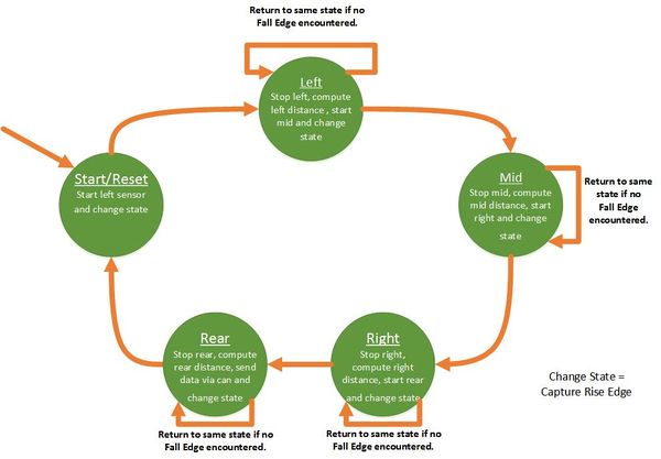
We are using the periodic callback functions.Hence we implemented the algorithm around those tasks.We used static variables in order to preserve the values incase functions are completed and the desired tasks are not completed yet. We used only the 1000Hz and 100Hz tasks.
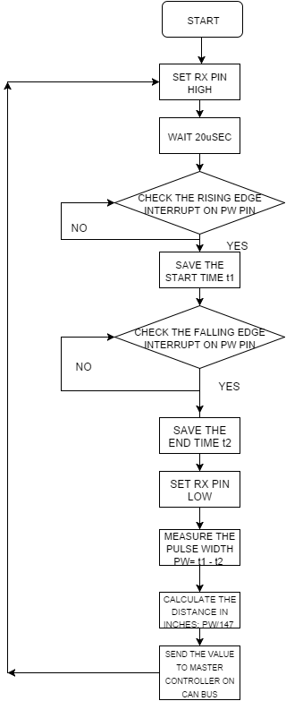
The following steps are for initializing, getting readings and calculating distance in inches for one sensor- Main init function: 1) Configure the PW pin of sensor as input. --1000Hz task:
2) Configure RX pin of the sensor as output and set it high.
3) Enable the Rising and the Falling edge interrupt on the PW pin of the sensor.
4) Note down the sys_get_uptime_us() at the rising interrupt. Let this time be T1.
5) Note down the sys_get_uptime_us() again when the falling edge is encountered. Let this time be T2.
6) To calculate the distance in inches, do - (T2-T1)/147.
--100Hz task:
7) Send this value to the Master controller via the CAN bus.
This is the snippet of our Interrupt function callbacks.
eint3_enable_port2(RightSensorPW_Pin, eint_rising_edge, eintCallbackright_Rise);
eint3_enable_port2(RightSensorPW_Pin, eint_falling_edge, eintCallbackright_Fall);
void eintCallbackright_Rise()
{
  //Note down the system start time for right sensor ( start_right_time)
}
void eintCallbackright_Fall()
{
 //Note down the current system time
 //Subtract the start_right_time from the current system time and divide the result by 147 to get the distance in inches.
}
Sensor: Technical Challenges
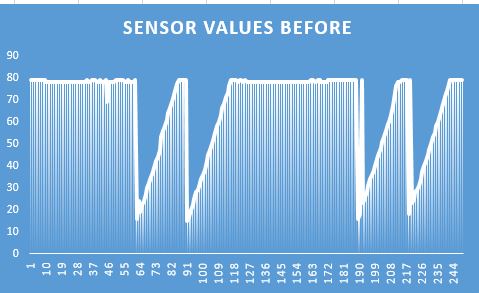
Issue #1 - Fluctuating sensor values: We observed random/fluctuation in the sensor values. Sometimes, the value was even zero.The primary reason was that we were using the ADC mode. ADC mode converts analog to digital values received from the sensors. The values were unstable and unreliable.We could have used an arbitration to get accurate values. But the SJSU one board has only 3 ADC pins and we have 4 sensors to mount. So,either way we could not use ADC mode.
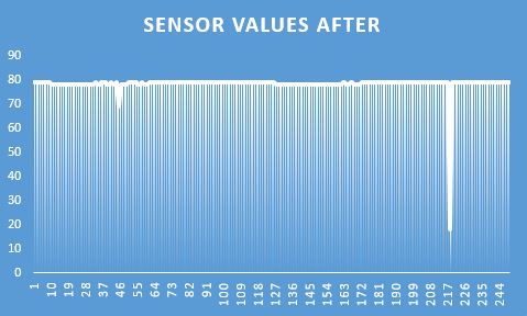
Solution: Switched from ADC mode to PWM mode to get more reliable values,with minimum spikes.PWM mode is a more reliable mode. We got accurate spikes on an oscilloscope and hence we used the PWM mode on the sensors.
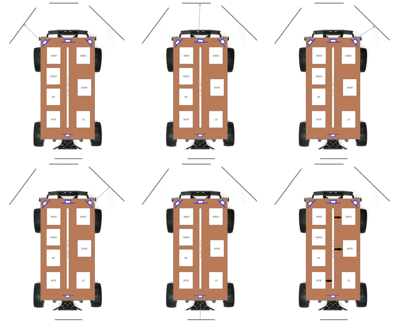
Issue #2 - The beams from two adjacent sensors collided with one another.The waves from the sensors travel in a V shape.This caused inter sensor value collision.
Solution: Increased the distance between the sensors and made sure sensors working serially and not in parallel.We increased the distance between the sensors to avoid inter sensor collisions.Also we turned one sensor on at a time. Hence we turned one sensor,got the values and then turned it off before moving on to the next one.The reliability increased considerably.
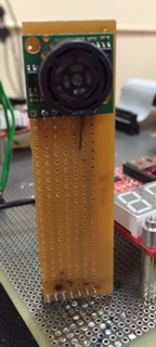
Issue #3 - The sensor when mounted on the car detected ground as obstacle.During the 1st demo, we mounted the sensors on the main board itself. This caused us getting values from the ground. This situation can be tricky when the car is on a slope.
Solution: Increased the height of sensors placed on the car.We mounted the sensors on custom PCB's and made sure no ground reflections were encountered.
Issue #4 - The sensors did not work on independent 5V supply.We provided a common 5V power to all the sensors. This caused fluctuations and hence unreliable values.
Solution: Switched the power supply to a more reliable and constant SJSU one board VCC.To reduce the spikes, we could have used a stable 5V power source. But we opted for stable power from the SJSU board. This reduced spikes.
Issue #5 - The sensors (Left and Right sensor) gave faulty values when placed at 45 degrees on the corner of the base board i.e. fall edge missed sometimes.The waves from the sensors got reflected from white or oil based painted objects if the sensors were placed at 45 degrees.
Solution: Increased the angle to cover wider area and avoid reflections.Finally we tested out many permutations and combinations to find the accurate angles at which the sensors reflected properly and waves didn't just pass on. Hence increasing the angles to more than 45 degrees helped get us accurate values.
Sensor Test Video
Motor and I/O Controllers
ThunderBird is a 2 WD truck. It is equipped with a ARRMA BLX brushless DC motor connected to an BLX80 ESC(Electronic Speed Control). The ESC drives the DC motor according to the PWM(Pulse Width Modulation) signal. The truck's front wheels are connected to a waterproof ADS-7M Metal Geared Steering Servo. The servo and the DC motor are controlled using the PWM pins of the SJOne board.
Motors
Pulse Width Modulation - Controlling DC motor
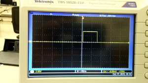
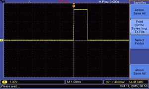
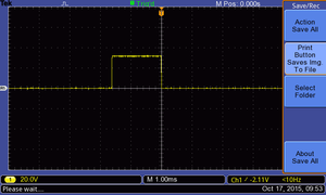
Pulse width modulation is a technique which is used to encode the analog signal into a pulsating signal. The signal is represented as a series of pulses. This signal can be easily generated using the pwm pins of the SJOne board. The ESC is initialized upon passing a PWM signal which is sent by the RF module on the truck. The type of signal is observed by hooking the PWM pin to the digital oscilloscope. The initialization signal is shown in figure 1. A resolution of 1ms is set on the oscilloscope. The PWM signal has a width of 1.5 ms. This signal initializes the ESC. Once the ESC's are initialized, the motors require a signal to accelerate and decelerate. The type of signals for moving the motor forward and backward are realized by hooking the output pin of the RF module to the digital oscilloscope. The forward and backward pwm signals at full throttle are shown in figures 2 and 3 respectively. The respective pwm signal pulses for moving the motors forward and backward are shown below.
- Acceleration PWM signal
- Forward full throttle - 2 ms
- Forward medium throttle - 1.8 ms
- Neutral - 1.5 ms
- Reverse PWM signal
- Reverse full throttle - 1 ms
- Reverse medium throttle - 1.2 ms
- Neutral - 1.5 ms
PWM Calculations
The PWM value to be set is determined from these calculations:
- PWM is a percentage of the signal frequency
- The signal is of 50 Hz i.e. 20 ms duration
- A 10% of the signal value gives a duration of 2 ms - 10/100 * 20 = 2 ms
The respective percentages for all the signal were calculated and the PWM signals were generated using the PWM.set function. The generated pulses from the SJOne PWM pin is passed to the ESC for initialization and controlling the DC motor. The ESC has 3 connections - Vcc, GND and PWM. SJOne board's GND and PWM are connected to the ESC. The Vcc is supplied from the battery pack.
A sample code demonstrating the PWM signals is written and the motors were controlled using the on-board SJOne switches.
Controlling Servo motor
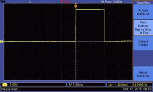
The servo motor channel in the RF module is hooked to the digital oscilloscope to determine the initial sequence. It is observed that when the RF transmitter is switched on, the RC remote sends a pwm signal which resets the servo to its starting position. This PWM signal re-centers the truck's wheels. The signal is realized by hooking the data pin from the first channel of the RF module to the digital oscilloscope. The PWM signal is shown in figure 4. The signal is having a pulse of 1.6 ms. The steering on the RC is moved left and right to determine the PWM signals. The signal values were noted from the oscilloscope. The values are tabulated below.
- Steering PWM signal
- Steer full right - 2 ms
- Steer full left - 1 ms
- Steer center - 1.6 ms
A PWM signal having a pulse width between 1.6 ms to 2 ms is used to control the steering towards right precisely. Similarly, a PWM signal having a pulse width between 1 ms to 1.6 ms is used to control the steering towards left precisely. The servo has 3 connections - Vcc, GND and PWM. The servo motor is not connected to a ESC. It doesn't get any voltage if it is not connected to the RF module. The servo motor operates at 6V. For testing, the Vcc of the servo motor is connected to the RF module. The GND from the RF module is made common with the GND from SJOne board. The PWN signal is given as an input from the SJOne board. The PWM signal values were calculated using the procedure shown above. The respective PWM signals were then sent to the servo motor using the PWM pin on the SJOne board for steering the truck.
The on-board switches on the SJOne board are used to steer the truck left and right. A sample code demonstrating this functionality is written and tested.
Speed Feedback Encoder
The car should maintain it's speed at all times. The factors affecting the car's speed include incline surfaces, weight of the car and low battery. During these cases, the car should increase and decrease its speed accordingly. There should be some mechanism to know the speed of the car. If you get a Traxxas car, it has an inbuilt device built into the car for measuring the car's speed. We are using optical sensor to detect the car's revolutions.
Optical Sensor
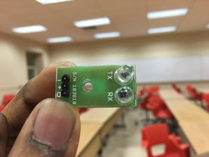
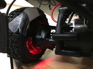
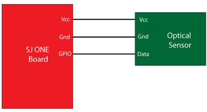
The optical sensor is shown in the figure 5. The optical sensor has Vcc, GND and data pins. The Tx led lights bright red and the Rx receives the reflected light from the Tx when it encounters a white surface. The optical sensor is mounted on the back rim of the car. A white paper is patched on to the tyre to reflect the light from the Tx into the Rx. The mounted optical sensor is shown in figure 6. The schematics for the optical sensor is shown in figure 7. The sensor's data pin is hooked to the GPIO pin. An ISR is called on that pin which will increment a counter value each time the interrupt is called. The counts are averaged using period functions and is displayed on the LCD for every second. The RPM is controlled according to these revolutions per second value. When the car goes on a slope, the pwm is increased to maintain the RPM and once the car climbs the slope, PWM value is decreased. It adjusts accordingly to maintain the RPM!
Precise Steer
The car should steer precisely according to the compass value and GPS value. The GPS tells the car where to go and the compass will tell the car in which direction it should go. The compass gives the values in degrees which lie in the range 0 to 360. The car's servo motor has a PWM range of 4 to 10 with 4 being the extreme left, 7 being the center and 10 being the extreme right. The compass degrees are divided into 17 sectors. The sectors 0 to 9 have values ranging from 0 to 180 degrees and sectors 10 to 17 have values ranging from 180 to 360 degrees. The sectors 0 to 9 drive the car right and the sectors 10 to 17 drive the car left. Each sector accounts to 20 degrees on the compass value. The entire PWM range is divided into sector value. The respective PWM value is set for the car's servo motor for precise steering control.
When the car encounters an obstacle, the precise control is stopped and the car steers to avoid the obstacle. Once the obstacles are avoided, the precise control is activated back.
Common Problems and troubleshooting
Issue #1 - The PWM signal width i see on the Oscilloscope is not correct!
Solution: I observed this while using PWM.set() in periodic functions. I did observe a correct pulse width on the oscilloscope when i did pwm.set in main(). But when i did pwm.set() in the periodic functions, i observed that the PWM signal is giving an incorrect pulse width. The reason is the PWM object is getting destructed. PWM object doesn't get destructed when used in a while(1) loop. When used in the periodic functions, it gets destroyed as soon as the function exits. The solution for this is to make a PWM Singleton Class that doesn't destruct. You can use methods such as motorcontrol.drive() and motorcontrol.steer() to set the PWM's for driving and steering the car. This is a better approach than making the PWM class global.
Issue #2 - The car's ESC initializes but the motor doesn't move irrespective of the PWM value!
Solution: Make sure that the battery is charged. Simple as that.
Issue #3 - How do i find the car's ESC initialization sequence?
Solution: You can use an Oscilloscope for this. As soon as the car is switched on the car's RC module sends a PWM signal to the ESC. The signal's width can be observed by hooking that PWM pin to the oscilloscope. The PWM value can be calculated according to the procedure described above. Give the respective PWM values and the ESC will be initialized.
I/O
Liquid Crystal Display
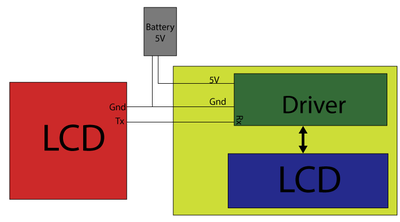
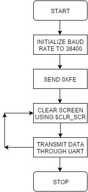
A 20x4 LCD(CM 204-1) is used for displaying the speed, sensor values and the start and end coordinates. A LCD driver by SJValley Engineering is used for accessing the LCD through UART. The driver and LCD are soldered on to the prototype board. A USB jack is soldered on-board to power the LCD using the 5V supply from the external battery. The connections between the driver and SJOne board is shown in figure 5. As soon as the LCD is powered on, it displays to enter 0xF0 which is the command for detecting the baud rate. After 0xF0 is sent, the data can be transmitted using UART. A baud rate of 38400 is used for displaying information on the LCD. If you are getting some junk values, make sure that the baud rate is set correct and check the soldering.
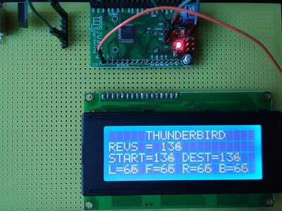
The LCD with displaying the values is shown in figure 6. The following helps you to organize information on your LCD.
- Commands for displaying information on LCD
- urt.put displays a character on the LCD
- urt.putlin displays a character on the LCD and moves the cursor to the next line
- $CLR_SCR is used to clear the screen
Common Problems and troubleshooting
Issue #1 - LCD is displaying only 2 lines, line 1 and line 3 when i power it on.
Solution: Check the connections. Make sure that the LCD is properly soldered to the driver.
Issue #2 - I am getting garbage values printed on the screen when i try to transfer information over UART
Solution: LCD is not initialized properly. Make sure you get the detecting baudrate information displayed on screen when the LCD is powered on.
Issue #3 - Is it okay to program the LCD while being connected to the SJOne board?
Solution: I didn't find any issues while programming the SJOne board with the LCD connected to it. However, some teams had issues with it.
Issue #4 - How do i update a single field on the LCD keeping the rest static?
Solution: I cleared the entire screen every 100 ms and it looked like only the values are being updated!
GPS Controller
Geographical controller module plays an important role in heading and positioning of autonomous car.It consists of 20GHZ GPS module and 9-DOF RAZOR IMU interfaced to SJ-one board.
The GPS module provides Latitude and Longitude co-ordinates for current position of car.The 9DOF Razor IMU incorporates three sensors - an ITG-3200 (MEMS triple-axis gyro), ADXL345 (triple-axis accelerometer), and HMC5883L (triple-axis magnetometer) - to give you nine degrees of inertial measurement.
SPARKFUN VENUS GPS with SMA CONNECTOR
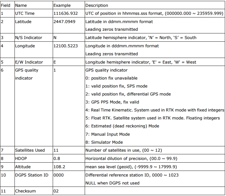
Sparkfun Venus GPS provides GPS information basically the current latitude and longitude in different NMEA standard messages such as
 $GPBOD - Bearing, origin to destination
  $GPBWC - Bearing and distance to waypoint, great circle
  $GPGGA - Global Positioning System Fix Data
  $GPGLL - Geographic position, latitude / longitude
  $GPGSA - GPS DOP and active satellites
  $GPGSV - GPS Satellites in view
  $GPHDT - Heading, True
  $GPR00 - List of waypoints in currently active route
  $GPRMA - Recommended minimum specific Loran-C data
  $GPRMB - Recommended minimum navigation info
  $GPRMC - Recommended minimum specific GPS/Transit data
  $GPRTE - Routes
  $GPTRF - Transit Fix Data
  $GPSTN - Multiple Data ID
  $GPVBW - Dual Ground / Water Speed
  $GPVTG - Track made good and ground speed
  $GPWPL - Waypoint location
  $GPXTE - Cross-track error, Measured
  $GPZDA - Date & Time
We use $GPGGA - Global Positioning System Fix Data
Time, position and fix related data for a GPS receiver.
Structure: $GPGGA,hhmmss.sss,ddmm.mmmm,a,dddmm.mmmm,a,x,xx,x.x,x.x,M,,,,xxxx*hh<CR><LF>
1 2 3 4 5 6 7 8 9 10 11
Example:
$GPGGA,111636.932,2447.0949,N,12100.5223,E,1,11,0.8,118.2,M,,,,0000*02<CR><LF>
Gpgca NEMA standard description table
The SparkFun Venus GPS comes with a default baud rate of 9600 bps and update rate of 1 Hz. It does NOT have an antenna, so we had to use Antenna GPS Embedded SMA. From our and experience of our project advisors we would recommend a GPS with refresh/update rate of ATLEAST 10Hz.
These are few commands which have 90% usage for most GPS module setup and troubleshooting.
1. Factory Reset
A0 A1 00 02 04 00 04 0D 0A
2. Configure the position update rate of GPS system(10 Hz).
A0 A1 00 03 0E 0A 01 05 0D 0A
3. Configure serial port. this command will set baud rate to 38400.
A0 A1 00 04 05 00 03 01 07 0D 0A
4. Configure NMEA message interval (this command will block all strings except GPGGA).
A0 A1 00 09 08 01 00 00 00 00 00 00 01 08 0D 0A
9 Degree of Freedom RAZOR IMU The 9DOF Razor IMU incorporates three sensors - an ITG-3200 (MEMS triple-axis gyro), ADXL345 (triple-axis accelerometer), and HMC5883L (triple-axis magnetometer) - to give you nine degrees of inertial measurement. The outputs of all sensors are processed by an on-board ATmega328 and output over a serial interface.
Compass
We are using sparkfun Razor IMU to give 9-degree of internal measurement. It has inbuilt triple axis gyroscope, accelerometer and magnetometer. The 8Mhz factory firmware gives compass heading using UART which is raw value of yaw, pitch and roll. The firmware for the Razor IMU is available on the GIT on various platforms such as Aurdino, Android, Processing etc. We are using Aurdino platform to download the firmware on the compass using Aurdino software. The same platform and firmware offers functionality to calibrate the compass. Having compass values is not enough for the project as it may or may not work on in real-time, when it is embedded on the car. Magnetometer is sensitive to magnetic field around, hence, the compass needs to be calibrated in the environment where it has to perform i.e on the car. The firmware is written in a way that it shows the deviation from the original value during calibration and gives a final value after the calibration to put as an offset in respective meter. All the meters, gyroscope, accelerometer and magnetometer, needs to be calibrated individually as the final heading is being calculated using values from all the three meters. https://github.com/ptrbrtz/razor-9dof-ahrs/wiki/Tutorial#sensor-calibration, calibration methods are given on the link mentioned earlier.
Master Controller
Master controller is responsible for communication between different controllers and sync each controller's data in directing the car in right direction. It receives ths start or stop command from Android application as soon it receives the command, Master sends motor with the respective message. Master controller listens to the data from sensors and GPS and compass, based on the obstacle avoidance algorithm and GPS co-ordinates, Master decides the right direction for the car and sends it to the Motor.
Heart Beat mechanism
Based on the data received from GPS Controller and sensor values, Master would decide the direction and steer values for the car and update the motor with the required direction and steer data. Direction and steer value computation is based on the below algorithm.
Obstacle avoidence algorithm
   if (start from android or switch)
       if (GPS is on)
        {
             if no obstacle
                follow gps
             if right obstacle detected
                Move straight
             if straight obstacle detected
                Move right
             if straight  and right obstacle detected
                Move left
             if left obstacle detected
                Move straight
             if left and right obstacle detected
                Move straight
             if left and straight obstacle detected
                Move right
             if all straight, left and right obstacles detected
                    if rear sensor detected
                       Stop
                    else
                       Reverse
         }
Bluetooth Control and Android application
Bridge/Android Controller
- James Sushanth Anandraj
- Athavan Kanagasabapathy
Hardware Design
A BTBEE Pro Bluetooth XBee socket chip connected to the SJOne board is the main hardware component used in Bridge communication.It is interfaced to the SJONE board over UART2. The SJONE board is in turn interfaced with the CAN Bus using a MCP2551 CAN Transceiver.
Hardware Interface
The BTBEE Pro is placed on the XBee socket of the SJOne board. This design was chosen over using I2C/SPI interface as SJONE board has a XBEE socket which can be used directly.The BT module communicates with the SJOne board using a UART interface. Uart2 on the SJONE board is used for this purpose. In order to enable the communication over UART, the switch on the SJONE board needs to set to UART2 position.
Software Design
The Software design of the Bluetooth and android Bridge control system consists of two main parts
1) Bluetooth to CAN Bridge Software on SJONE board
2) Thunderbird Android Application
Bluetooth to CAN Bridge
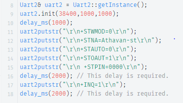
The Bluetooth chip is initialized by passing the following commands over bluetooth.
Once the chip the initialized data is sent and received from the android app to the SJONE board by treating the Bluetooth connection as a UART bus using uart api's like uart2.getChar and uart2.printf.
In our bridge controller we have written the algorithm to parse input characters from uart and take action based on the sequence of characters that make up a command. The bridge controller responds to the following commands.
a) Hello - Hello message from android. The SJONE board responds with the current GPS coordinates.
b) Start - Start message from android. The SJONE board responds with HI to begin exchange of one GPS checkpoint value.
c) Stop - Stop message from android. The SJONE board responds with the number of GPS coordinates it received from Android.
d) Good - Car start message from android. The SJONE board transmits a start message to Master controller to start transmitting commands on can bus to control the car.
e) Bad - Emergency start message from android. The SJONE board transmits a stop message to the Master controller to send stop command on the can bus to all controllers.
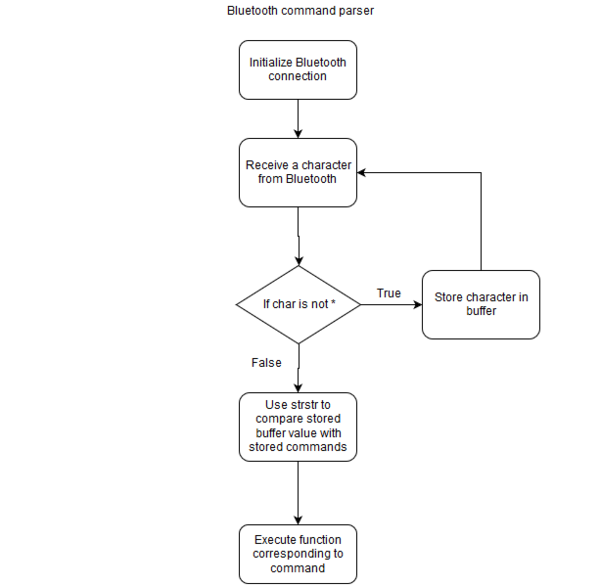
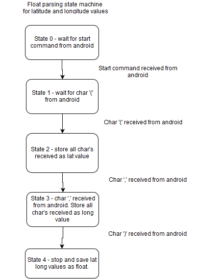
Parsing float information from android
We have used a state machine approach to receive latitude and longitude float values from android app. The state machine is explained as a flowchart below.
Updating analytics values to android
Updating analytics value to the android app is an important functionality of bluetooth controller. We read all messages on the can bus and store the values in dbc defined global variables. At 1 hz we send this out to the Android app. The analytics values that are sent to android are as follows
a) Induvidual sensor readings
b) Last command issued by Master
c) Speed of the car from Motor
d) Latitude, Longitude and Heading values from GPS.
Testing & Technical Challenges
Describe the challenges of your project. What advise would you give yourself or someone else if your project can be started from scratch again? Make a smooth transition to testing section and described what it took to test your project.
Include sub-sections that list out a problem and solution, such as:
My Issue #1
Discuss the issue and resolution.
Conclusion
Conclude your project here. You can recap your testing and problems. You should address the "so what" part here to indicate what you ultimately learnt from this project. How has this project increased your knowledge?
Project Video
Upload a video of your project and post the link here.
Project Source Code
References
Acknowledgement
Any acknowledgement that you may wish to provide can be included here.
References Used
List any references used in project.
Appendix
You can list the references you used.
