F15: Laser Security System
Contents
Laser Security System
Abstract
The Laser Security System allows to maintain security in a room. For example by shining a laser across a door's entrance to a photo-resistor inside a box. When laser is block from the photo resistor we send an alerting message via bluetooth communication to a guarded slave micro controller. The slave micro controller, Arduino and cellular shield will work together to send a text message to alert the owner that there has been a breach.
Objectives & Introduction
This security system will be using GPIO pins on the SJSUOne Board to detect if the laser has been trip. It will use TX and RX lines to connect to the RN42-XV Bluetooth Module using serial communication (UART). There two Bluetooth modules, each one is connected to a SJSUOne Board and will communicate with each other, in order to specify when we should send a text message. The Arduino module will provide power to the cellular shield and retrieve the information from the slave micro controller to send the according commands to the cellular shield.
Objectives for this project:
- Research and design the schematics to connect a light detection circuit to one of the SJSUOne Board and showing the output by lighting an LED
- Research bluetooth communication and integrate it to the light detection circuit
- Research gsm communication
- Complete hardware design
- Test functionality of the system
- Able to receive text messages from shield and send commands through text message
- Detect and connect to other bluetooth devices
Team Members & Responsibilities
Emmanuel Gonzalez: Software Implementation and Report Writer
Irlanda Altamirano: Hardware Implementation and Report Writer
Schedule
| Week# | Date | Planned Task | Actual |
|---|---|---|---|
| 1 | 10/12-10/18 |
• Project Approval • Project Research • Purchase all required parts |
• Project Research |
| 2 | 10/19-10/25 |
• Build Schematics • Order all parts • Test individual components |
• Schematics for the overall system is done • Order all parts |
| 3 | 10/26-11/1 |
• Begin hardware design interfacing a laser, photo-resistor and SJ One Board • Test the hardware design |
• Hardware design implementation started |
| 4 | 11/2-11/8 |
• Trouble shoot hardware design with • Test the hardware as a whole |
• Hardware design implementation interfacing a laser, photo-resistor and SJ One Board completed |
| 5 | 11/9-11/15 |
• Research about Bluetooth communication • Build Bluetooth circuit |
• Test the hardware design • Starting software interfacing previous hardware implementation • Read data sheet for Bluetooth communication |
| 6 | 11/16-11/22 |
• Interface Bluetooth communication with SJ One Board • Test the complete hardware interface |
• Order another board for Bluetooth communication • Research more about Bluetooth communication |
| 7 | 11/23-11/29 |
• Test Bluetooth communication with SJ One Board |
• Hardware design implementation interfacing a laser, photo-resistor, bluetooth communication and SJ One Board started |
| 8 | 11/30-12/6 |
• Complete the software interfaces for laser, SJ One Board and Bluetooth communication • Implement text message feature with Bluetooth communication |
• Debugging bluetooth communication interface |
| 9 | 12/7-12/13 |
• Finish Debugging text message communication feature • Start writing project report • Test system design |
• Started implementing SMS feature with bluetooth communication • Continued the project report |
| 10 | 12/14-12/16 |
• Complete system testing • Finish project report |
• Debugging SMS/ bluetooth communication • Completed system testing • Created video for presentation • Finish project report |
| 11 | 12/17 |
• Demo Project on Thursday, December 17, 2015 |
• Demo Project completed |
Parts List & Cost
| Quantity | Item | Cost |
|---|---|---|
| 2 | SJ One Board | $80.00 |
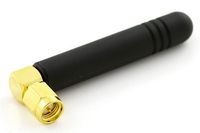
| 1 | Quad-band Cellular Duck Antenna SMA | $7.95 |
| 2 | RN42-XV Bluetooth Module - PCB Antenna | $24.95 |
| 1 | Mini Photocell | $1.50 |
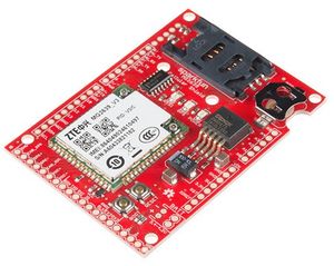
| 1 | SparkFun Cellular Shield - MG2639 | $69.95 |
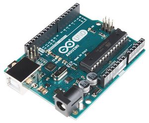
| 1 | Arduino Uno R3 | $24.95 |
| 1 | LED | $0.10 |
| 1 | Resistors 8.2K, 2.7K and 1K ohms | $0.20 |
Design & Implementation
The design section can go over your hardware and software design. Organize this section using sub-sections that go over your design and implementation.
Hardware Design
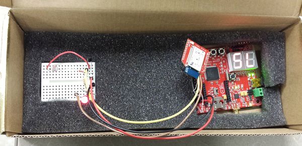
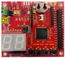
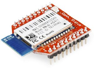
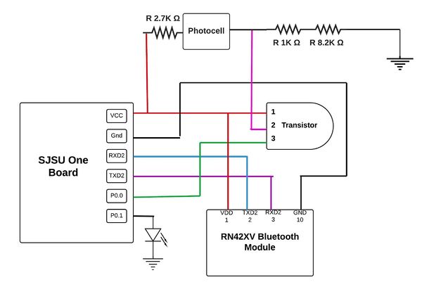
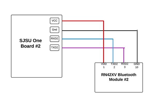
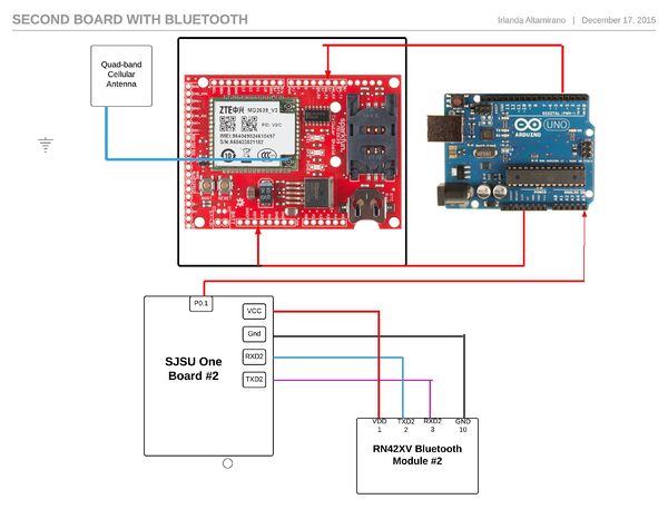
Figures 1-5 show the modules needed for this project as listed in the Parts list. The security system is made up of two main two components, the laser detection component and the transmitting text messaging component/ receiving text message commands. Figure 7 is the first circuit, it includes the master SJSU One Board connected to a bluetooth module by using UART communication. The master SJSU One Board is also connected to the laser detection circuit. The circuit is comprised of a transistor that relies on a set amount of current to create a channel from the collector to the emitter. The photocell is used to increase and decrease the resistance, thus limiting or increasing the current flow. When there is enough light or the laser is shining on the photocell the resistance decreases allowing the current to travel to ground instead of the base of the transistor. When the laser is interrupted from shining on the photo cell that is encased in a box then this produces high resistance, and allowing the current to flow into the base of the transistor instead of going to ground. The micro controller will take this input and and output 3.3v through another gpio pin to an led to indicate the laser has been trip.
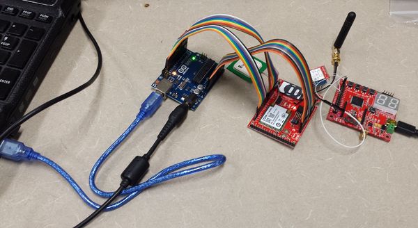
once we receive input from the photo circuit, the micro controller will transmit data (UART communication) to the bluetooth module and will send the information to the other bluetooth module which is connected to the second micro controller. The second circuit is shown in Figure 8 which shows the second SJSU board. This board is connect to a bluetooth module that receives information when the laser has been interrupted. The SJSU One board #2 connects to the Arduino and communicate through GPIO. When the Arduino gets an input from the second board it sends commands to the cellular shield to send a text message.
Hardware Interface
To sync our the devices and connect them via bluetooth we used an app called "AT command" from the Android app store which can be downloaded for free. First we make sure our circuits are powered on. Then we open the App and scan for nearby bluetooth devices using an AT command. once we see the desired device name/serial number, we store the serial number on the master bluetooth module. We then send another AT command connect to the master SJSU board to the slave SJSU board so that they can communication thru bluetooth. Note that one bluetooth module must be set to master, since the module default state is slave.
The command inX is used to search for nearby bluetooth devices, "in" stands for inquiry and the X represent a variable number that tells the searching bluetooth module for how long to search in seconds.
After the searches in X seconds is complete then we connect to the second module by sending the character c.
- note again once you find the desire bluetooth module, the serial number must be store in the master bluetooth module before we can connect.
another useful command is "h", which provides you with the list of AT commands and a description of their purpose.
After once the bluetooth modules are connected they can begin transmitting data. Allowing both components to do their intended tasks.
Software Design
Implementation
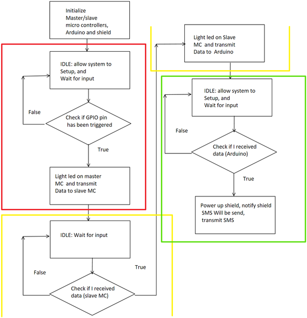
The first step was to initialize the GPIO pins for the laser detection. Then we initialized the micro controller for UART communication. We Created to one function for the master to transmit and another for the slave to receive. Within our run function for the master, we are continuously checking if the light has been block. If the light is blocked the master will transmit data to the slave via Bluetooth. Note that the Bluetooth devices need to be initialized using AT commands. one Bluetooth device needs to be set to master so it can transmit to the other. Once the Bluetooth's are initialized, the master will search for any nearby devices it can communicate with. once we see our slave Bluetooth device we need to record its name in the master Bluetooth device so it can easily pair with this device the next time we setup communication. Once the Slave receives data that the laser has been trip, the slave will the communicate with the Arduino one board using a GPIO pin. The Arduino board initializes the cellular shield and provides power to the board. If the Arduino receives the signal from the slave micro controller, the Arduino will sent commands to the cellular shield. cellular shield will then to send a text message to the predefined phone number. If the Arduino does not receive the signal from the slave micro controller, it will stay idle until it is triggered by the slave micro controller.
Testing & Technical Challenges
The following difficulties were encounter during this project but were able to successfully overcome them to delivery a functional project. Most of the time spent in this project was testing and debugging our program.
My Issue #1
At the beginning of the project we encounter some problems since we never had worked with bluetooth communication, gsm communication,and interfacing it with laser detection circuit between two microcontrollers. This was challenging but not impossible to solve this problem so from our part we conducted a lot of research before even building the first circuit in this project which was the light detection sensor circuit.
so we wouldn't feel overwhelmed, we broke our project into three parts, the laser detection component, the bluetooth communication component, and gsm communication component. We made sure each component was working before moving onto the next component.
My Issue #2
Another problems we encounter in this project was that the cellular shield was not receiving enough power to work correctly. We tried sending commands and or send text messages but we were not receiving any feedback from the board. To solve this problem we connected an external power supply to the Arduino board and connected the voltage pin to the cellular shield board.
Conclusion
After overcoming the problems associated with this project and a lot of software debugging was performed we were able to successfully complete this project. Through out this project we learn about how to implement bluetooth communication between two microcontrollers from the hardware and software side. Understanding data sheets for the devices and obtaining the information needed to implemented the desire functionality from the bluetooth module, SJSU one board, Arduino board, and cellular shield was crucial in order to obtain a successful outcome and create a fully functional text message security system.
Project Video
Project Demo: https://youtu.be/Z2P5bmgPy7c
Project Source Code
References
Acknowledgement
We would like to thank the following people for their contributions and support during this project:
Preetpal Kang and Dr. Haluk Ozemek
References Used
Appendix
Bluetooth Module
https://www.sparkfun.com/products/11601
LPC1759 Datasheet
http://www.nxp.com/documents/data_sheet/LPC1759_58_56_54_52_51.pdf
LPC176x/5x User manual
http://www.nxp.com/documents/user_manual/UM10360.pdf
RN42XV Bluetooth Module
http://cdn.sparkfun.com/datasheets/Wireless/Bluetooth/RN42XV.pdf
General Purpose Transistor
file:///Users/Irlanda/Downloads/410427.pdf
