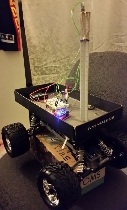
F15: Autonomous Mobile
Contents
Abstract
Tesla Motors just announced their own developed technology on the October 14, 2015 - Autopilot on all of their currently supporting vehicle Model S. Using some of the top-of-the-line industrial sensor - a forward radar, a forward-looking camera, 12 long-range ultrasonic sensors, and a high-precision digitally-controlled electric assist braking system, an automated driving capabilities luxury car is being delivered. All of those feedback modules were being involved differently in the autopilot system. With a similar concept on the self-driving capability model RC car, our team is going to deliver similar technology with the knowledge on different peripheral drivers.
Objectives & Introduction
This program is target to deliver a self-driving vehicle with GPS/compass module and bluetooth communication with Android. Obstacle avoidance will only be added if time is permitted. The below are the tasks we aim to deliver: Motor and Servo, GPS, Compass, and Bluetooth enable.
Team Members & Responsibilities
- Kenneth Chiu
- B.S. Computer Engineering
- Yuyu Chen
- B.S. Computer Engineering
Schedule
The point of the schedule is for readers to assess how to pace themselves if they are doing a similar project.
| Week# | Start Date | End Date | Task | Status | Completion Date |
|---|---|---|---|---|---|
| 1 | 10/16/2015 | 10/22/2015 | Idea confirm, order project parts | Completed | 10/22/2015 |
| 2 | 10/23/2015 | 10/29/2015 | Start building Android App, connect motor controller, test motor & servo | Completed | 10/28/2015 |
| 3 | 10/30/2015 | 11/05/2015 | Get Compass, GPS, and Bluetooth modules working (implement drivers to output raw data) | Completed | 11/05/2015 |
| 4 | 11/06/2015 | 11/12/2015 | Calibrate Compass and Parse GPS data (get useful data) | Completed | 11/20/2015 |
| 5 | 11/13/2015 | 11/19/2015 | Integrate Compass and GPS together (heading, bearing, distance) | Completed | 11/29/2015 |
| 6 | 11/20/2015 | 11/26/2015 | Continue working on Integration of Compass and GPS algorithm | Completed | 11/29/2015 |
| 7 | 11/27/2015 | 12/03/2015 | Integrate motor with Geographical unit | Completed | 11/29/2015 |
| 8 | 12/04/2015 | 12/10/2015 | Test Autonomous car, work on Bluetooth integration | Completed | 12/16/2015 |
| 9 | 12/11/2015 | 12/17/2015 | Test Autonomous car | Completed | 12/16/2015 |
Parts List & Cost
| Qty | Description | Manufacturer | Part Number | Total Cost | Links |
|---|---|---|---|---|---|
| 1 | SJ One Board [1] | Preet | SJ-one | $80 | http://www.socialledge.com/sjsu/index.php?title=SJ_One_Board |
| 1 | Traxxas Stampede: Monster Truck [2] | Traxxas | 36054-1 | $199.95 | http://www.amazon.com/Traxxas-36054-1-Stampede-Monster-Ready-To-Race/dp/B00OK3AJWW/ref=zg_bs_166587011_6 |
| 1 | GPS Bee kit (with Mini Embedded Antenna) [3] | Adafruit | MTK3339 | $39.95 | http://www.adafruit.com/products/746 |
| 1 | Triple Axis Compass Magnetometer Sensor Module [4] | Adafruit | HMC5883L | $9.95 | http://www.adafruit.com/products/1746 |
| 1 | BTBee Pro Bluetooth XBee Wireless Module [5] | ITEAD Studio | BR010292 | $14.99 | https://www.bananarobotics.com/shop/BTBee-Pro-Bluetooth-XBee-Wireless-Module |
Design & Implementation
Hardware Design
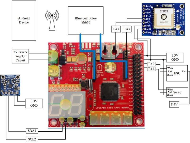
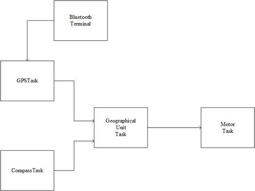
With the idea in building a self-driving vehicle, this schematic show how we were able to do it. With the thinking of a well-equipped self-driving car, GPS and compass module is a must to give the car itself a coordinate. Also, motor and servo are very important for the car to run freely to any direction. Bonus, a Bluetooth module that can help user to transfer their desire location coordinate and design a route for that. Basically, with all these components together, a prototype of a self-driving vehicle is created.
Hardware Components
Traxxas 36054-1 Stampede: Monster Truck
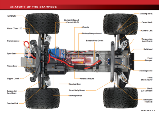
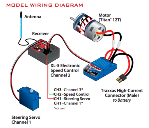
We choose this monster truck because of multiple reasons. Traxxas is a well-known brand name for a typical RC car. Their cars are very fast, durable, and high quality. Although the price might be a bit pricey, we don't have to worry about replacing broken parts or worn parts. This prototype was designed to be suitable for any kind of road conditions. You don't want to change another ride if you are by the beach or hills. Monster trucks are designed to be offroad and every conditions. The car might be a bit slow onroad but the speed is not our main concern at this moment. Most importantly, this car has 1 electronic motor, 1 ESC and 1 Servo. The reason for us to choose this model is because we can get to control the motor and servo separately so that a minor degree of turn can be made. The motor is to control the rear-wheel accelerate and decelerate. The servo is to provide us a control of the front wheel so the car can follow the optimal route.
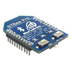
BTBee Pro Bluetooth XBee
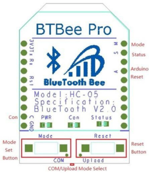
We have tried couple bluetooth module in the market and this one is by far the best that we can get. This BTBee Pro is a serial port Bluetooth module which can be compatible with the shields with XBee sockets. SJ one board come with a xBee shield and this is a best experience that we can have. It's designed for Bluetooth wireless transfer. It can support Slave and Master mode although we are using it as Slave mode only. When it's plugged into xBee socket, it uses UART for transparent transmission. With the build-in AT command, we can change some default settings like the module address, module name, module mode, and baud rate.
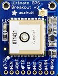
MTK3339 Ultimate GPS
The MTK3339 Ultimate GPS module from Adafruit was chosen because it provides us with more than enough functionalities. All we needed from the GPS module was the longitude and latitude from raw NMEA sentence.
It provides an accuracy of 5-10 meters (or worse if indoors) with its 22 satellites transmitting data to the GPS module. An external antenna can be attached to improve accuracy. The GPS module can be interfaced to a micro controller through UART interface with a default baud rate of 9600. It can be powered on with 3.3V-5VDC, which can be provided from the SJOne board. It provides an LED indicator that blinks at about 1Hz while searching for satellites and blinks once every 15 seconds when a fix is found to conserve power. The GPS module will allow us to calculate the bearing and destination from its current GPS coordinate and the destination coordinate.
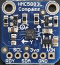
HMC5883L Triple Axis Compass Magnetometer
The HMC5883L Triple-axis Magnetometer module from Adafruit was chosen because it provides us with heading relative to magnetic north.
Most importantly, it allows us to steer toward our destination. The magnetometer has 6 data registers that can be read from which contains the 8 bit MSB or LSB x,y,z coordinates. Although the z-axis is provided, it is not used but can be useful in future projects. The magnetometer sensor uses I2C interface to communicate with a microcontroller. It can be powered on with either 3V-5VDC. There is also a Ready pin that can be used to speed up reading the data registers.
Hardware Interface
Traxxas 36054-1 Stampede: Monster Truck
The peripheral interface of the motor and servo are using PWM(Pulse Width Modulation) signal. PWM is normally used for getting analog results with digital means. PWM allows us to vary how much time the signal is high in an analog fashion. While the signal can only be high (usually 5V) or low (ground) at any time, we can change the proportion of time the signal is high compared to when it is low over a consistent time interval. A square wave of the digital control can be represented of the signal between on and off. PWM can have many of the characteristics of an analog control system, in that the digital signal can be free wheeling. One of the parameters of any square wave is duty cycle. Below are the frequency and duty cycle of our motor and servo respectively. The ON time can be varied completely between signal being off to being fully on, 0% to 100%, and all ranges between.
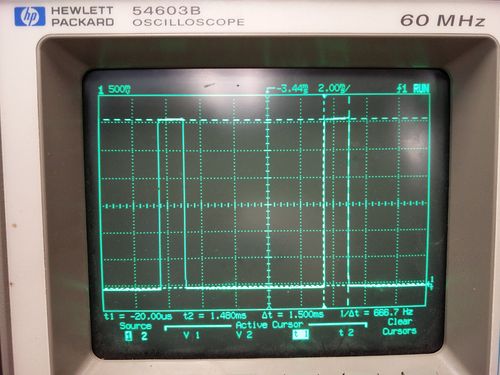
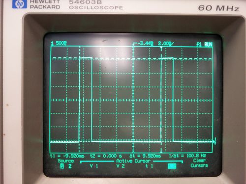
When the signal is high, we call this “on time”. To describe the amount of “on time” , we use the concept of duty cycle. Duty cycle is measured in percentage. The percentage duty cycle specifically describes the percentage of time a digital signal is on over an interval or period of time. This period is the inverse of the frequency of the waveform. Frequency/period are specific to controlling a specific servo. A typical servo motor expects to be updated every10 ms with a pulse between 1 ms and 2 ms, or in other words, between a 5 and 10% duty cycle on a 100 Hz waveform.
void motorTask::resetAll(float val)
{
   //motor.set(val); // neutral 15
   servo.set(val); // center15
   return;
}
void motorTask::turnLeft(float val)
{
   servo.set(val); // left , 19.5 max
   return;
}
void motorTask::turnRight(float val)
{
   servo.set(val); //rights 10.5 max
   return;
}
void motorTask::motorForward(float val)
{
   motor.set(val); // 15% motor speed, 16.5
   return;
}
void motorTask::motorBackward(float val)
{
   motor.set(val); //13.5
   return;
}
BTBee Pro Bluetooth XBee
We are using UART(Universal Asynchronous Receiver Transmitter), a simple way but very efficient, to transfer data between the Bluetooth and SJone board. As long as we found the build in baud rate and the baud rate of our Bluetooth device, the connection between them are set. There is one wire for transmitting data, and one wire to receive data. We have set the Bluetooth transmitter baud rate to be 115200bps, then the receiver must be listening on the other end at the same speed.
With the help of the XBee shield, BTBee Pro is fully insert onto the SJ one board with no external pins connected. The following is the pins config of the XBee Bluetooth shield.
| Number | BTBee Pro PIN | XBee shield |
|---|---|---|
| 1 | VCC | VDD |
| 2 | DOUT | DOUT |
| 3 | DIN | DIN |
| 5 | RESET | RESET |
| 9 | PAIR | DTR |
| 10 | GND | GND |
| 19 | STATUS | DIO1 |
| 20 | MODE | DIO0 |
MTK3339 Ultimate GPS
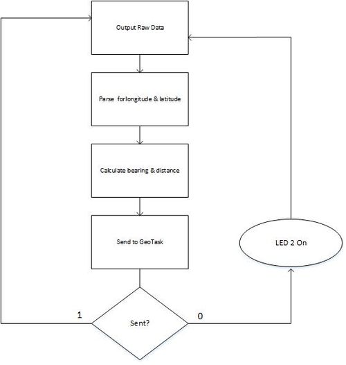
The GPS module is powered on by a minimum of 3.3V and is interfaced over UART to send and receive data. The 3.3V output from the SJOne board is used to power the board and the ground pin is connected to the GND pin of the GPS. Since it is using UART interface, the TX pin from the GPS is connected to RX of the SJOne board and the RX pin of the GPS is connected to TX pin of SJOne board. Once properly connected, the baud rate is set to 9600Hz for it to properly communicate with the SJone board. The GPS will begin outputting raw NMEA sentences by using the gets() function. The raw NMEA sentence is then filtered out by sending a packet during initialization to filter out different formats of of the raw sentences and output only $GPRMC (Recommended minimum specific GPS/Transit data). Only the latitude and longitude from the parsed NMEA sentence was needed, therefore another parser was developed to grab only the latitude and longitude data by the tokenize() function. Using the longitude and latitude, the bearing and distance can be calculated.
      Example: $GPRMC,225446,A,4916.45,N,12311.12,W,000.5,054.7,191194,020.3,E*68
                       1     2    3    4    5     6    7    8      9     10  11 12
| Number | Raw form | Description |
|---|---|---|
| 1 | 225446 | Time of fix 22:54:46 UTC |
| 2 | A | Navigation receiver warning A = OK, V = warning |
| 3 | 4916.45 | Latitude 49 deg. 16.45 min |
| 4 | N | North |
| 5 | 12311.12 | Longitude 123 deg. 11.12 min |
| 6 | W | West |
| 7 | 000.5 | Speed over ground, Knots |
| 8 | 054.7 | Course Made Good, True |
| 9 | 191194 | Date of fix 19 November 1994 |
| 10 | 020.3 | Magnetic variation 20.3 deg |
| 11 | E | East |
| 12 | *68 | mandatory checksum |
    if (counter == 3)
       {/*convert the 3trd token latitude*/
           latTemp = atof(token);
           latTemp = convertFromNmeaSentenceToDecimalCoord(latTemp, "m"); //"m" for meridian
       }
       /*If 4th token == South multiply by -1*/
       if (counter == 4)
       {
           if (*token == 'S')
           {
               latTemp *= (-1);
           }
       }
       latitude = latTemp;
bearing = atan2( sin(longDiff_rad)*cos(lat2_rad), cos(lat1_rad)*sin(lat2_rad)-sin(lat1_rad)*cos(lat2_rad)*cos(longDiff_rad))
   Distance formula:
   haversine formula: a = sin^2(latDiff_rad/2) + cos(lat1_rad) * cos(lat2_rad) * sin^2(longDiff_rad/2)
    formula: c = 2 *atan2(sqrt(a), sqrt(1-a))
    d = Radius of Earth * c
HMC5883L Triple Axis Compass Magnetometer
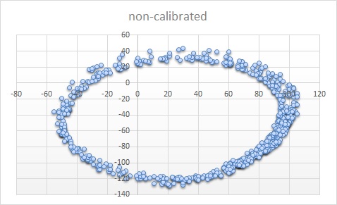
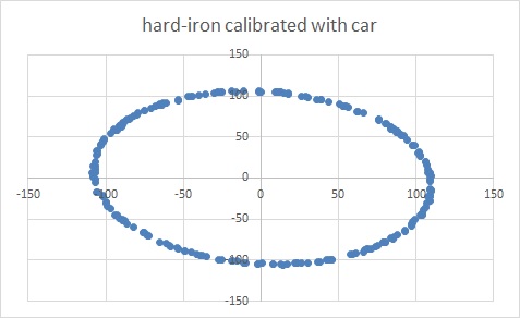
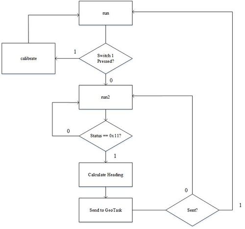
The compass module is powered on by a minimum of 3.3V and communicates with the SJone board via I2C interface. The compass module has 6 data registers which contains the 8 bits MSB or LSB x,y,z coordinates in 2's complemented form. The MSB and LSB values of each coordinate were combined together to provide useful data in order to calculate the heading. Only the x and y values were used to calculate the heading. The reason why the compass module is far away from other electronics is because the compass module is very sensitive to surrounding magnetic fields. Placing it away from the servo and motor increased the heading degree accuracy when comparing to compass apps from smartphones. The compass module needed to be calibrated to its environment due to the effects of hard iron and soft iron distortions. Only hard iron was taken into account because it is a constant value and is just an offset. The soft iron offset is ignored due to varying magnetic field in different environment. In the graph plot below, there is a huge difference in distortion which resulted in 30 degree error with the non-calibrated module. The calibrated module reduced the error to just 10 degrees.
  float heading = (float) atan2(float(y), (float(x))); // in radian
   if (heading < 0)
   {
       heading += (2 * M_PI);
       heading *= 180 / M_PI;
   }
   else
       heading *= 180 / M_PI;
Software Design
Implementation
This section includes implementation, but again, not the details, just the high level. For example, you can list the steps it takes to communicate over a sensor, or the steps needed to write a page of memory onto SPI Flash. You can include sub-sections for each of your component implementation.
motorTask
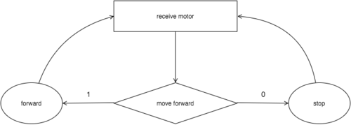
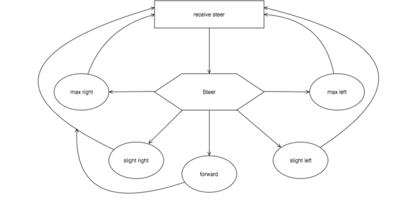
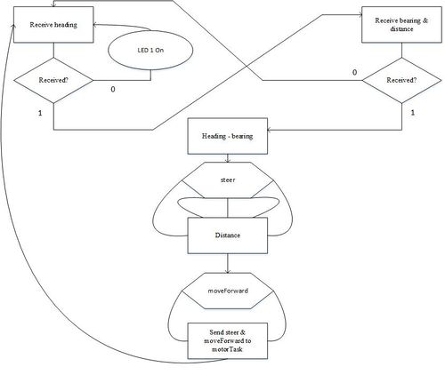
The motorTask will receive the steering enumeration and moveForward enumeration to control the autonomous movement. There are 5 different kinds of steering and 2 kinds of movement as listed in geoTask.
Bluetooth
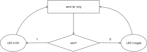
The Bluetooth receiver software was written so that it can receive the longitude and latitude from a device with Bluetooth capability. The Bluetooth receiver was written in terminalTask due to its easy implementation. A handler and a command line prompt was added to the terminalTask and using extern to pass the received coordinates to the gpsTask.
Format for the command line prompt:
Bluetooth lat long
extern float lati;
extern float longi;
bearing = computeBearing(latitude, longitude, lati, longi );
distance = computeDistance(latitude, longitude, lati, longi );
GPSTask
The GPSTask will parse the raw NMEA sentence for $GPRMC and get the current location of the car. The bearing and distance is then calculated from its current location and destination. The bearing and distance is then sent over a queue to the GeoTask for further processing. The calculated bearing is in degrees and the calculated distance is in meters.
CompassTask
The compassTask will compute the heading and convert it from radians to degrees. It will check the status register if there is new data available. All 6 registers must be read in order to get new data. The computed heading is then sent over a queue to the GeoTask for further processing.
GeoTask
The geoTask computes which direction the car will steer in order to get to its destination. There are 5 different kind of steering mode: slight right, max right, slight left, max left, and forward. Depending on the distance to the destination, the car will move forward until it arrives at its destination with a error margin of 5 meters, as provided by the GPS module hardware description. The steering and motor enumeration is then sent over a queue to the motorTask to control the autonomous movement.
Testings
Motor Testing
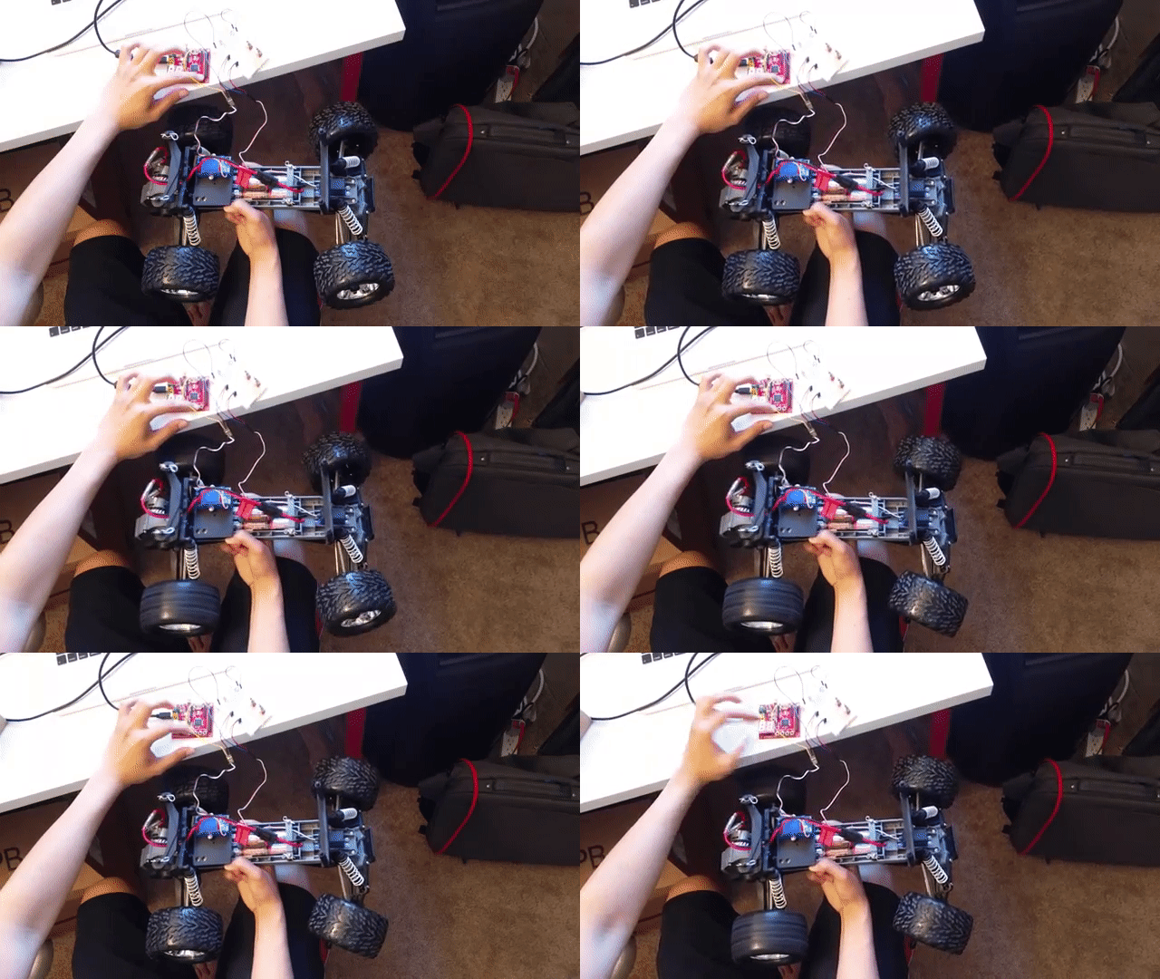
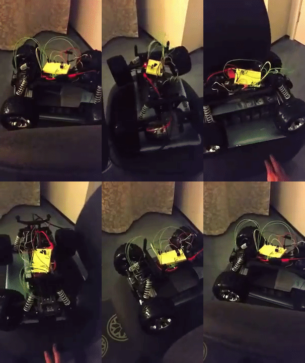
The motor and servo of the car were initially tested by using the 4 on-board switches to test: forward movement, backward movement, turn left, and turn right. When the car was integrated with the geographical unit, spinning it on a turn-able chair verified that the compass and GPS module were able to control the steering of the car.
GPS Testing
Testing the GPS module was simple. It is easy to verify how accurate the GPS module by checking the GPS module's coordinates by inputting it into Google Maps.
Compass Testing
To verify the correct heading relative to magnetic north, it is possible to check it a smartphone with a compass app. This is how it is possible to check how many degrees the heading was off.
Bluetooth Testing
Having print statements in Hercules allowed us to check if the destination coordinates are being updated through bluetooth. TerminalTask would also provide a "Command fail" if inputting an incorrect prompt.
Car Testing
The whole car was tested in an open area where there were not many objects to obstruct its free driving. Testing it in a confined space does not allow the car to turn. The cars path to its destination is unpredictable because we did not implement waypoints.
Technical Challenges
Calibration of 3-axis magnetometer
Issue: Need to calibrate compass because center is not at origin. Huge error of 20-30 degrees. Hard iron cause shift in x,y axis. Soft iron distort shape of circle into an ellipse. Need to keep compass on a flat surface because a tilt will affect x,y values
Resolution:Calibration was applied by subtracting the hard-iron offsets. Heading error reduced to range of 0-10 degrees. Ignoring soft-iron distortion because value is not constant and changes with location.
Compass placement
Issue: Compass placement: The compass was first placed in front of the car, away from the motor. Thinking that it might not be affected by its magnetic field.
Resolution: The servo (front of the car) also affected the compass. The placement of the compass was placed at least 1 feet away from any other component. During test drives, the car drove smoothly.
Nothing to stop it from crashing
Issue: During test drives, the car will crash into objects or walls in confined space.
Resolution: The car will reach its destination without help only if it is test driven in an open space with minimal object to obstruct its driving.
Conclusion
Conclude your project here. You can recap your testing and problems. You should address the "so what" part here to indicate what you ultimately learnt from this project. How has this project increased your knowledge?
Project Video
Motor and Servo: https://youtu.be/AdKw1G4GNOM
Motor and Servo (updated): https://youtu.be/y9YGl9JmKUU
Geographical Unit integration with motor (compass only): https://www.youtube.com/watch?v=N3GIjYgyP60
Self Driving Field Test 1: https://www.youtube.com/watch?v=R7_ALVbJFRE
Self Driving Field Test 2: https://www.youtube.com/watch?v=9BRb-uHcNx4
Project Source Code
References
Acknowledgement
Android application: https://github.com/kennethchiu22/AndroBluetooth
Compass sensor: https://learn.adafruit.com/downloads/pdf/adafruit-hmc5883l-breakout-triple-axis-magnetometer-compass-sensor.pdf
Motor and Servo: http://www.socialledge.com/sjsu/index.php?title=SJ_One_Board#Motor_.26_Servo_Control
References
[1] http://www.socialledge.com/sjsu/images/d/de/2012SJOneBoardSchematic.pdf
[2] https://traxxas.com/sites/default/files/24054-36054-37054-OM-N-EN-R02_0.pdf
[3] http://www.adafruit.com/datasheets/GlobalTop-FGPMMOPA6H-Datasheet-V0A.pdf
[4] http://www.adafruit.com/datasheets/HMC5883L_3-Axis_Digital_Compass_IC.pdf
[5] ftp://imall.iteadstudio.com/Modules/IM121115002_BTBeepro/DS_IM121115002_BTBeepro.pdf
[6] https://learn.sparkfun.com/tutorials/pulse-width-modulation
Grading Criteria
- How well is Software & Hardware Design described?
- How well can this report be used to reproduce this project?
- Code Quality
- Overall Report Quality:
- Software Block Diagrams
- Hardware Block Diagrams
- Schematic Quality
- Quality of technical challenges and solutions adopted.
