F15: TopGun
Contents
- 1 Grading Criteria
- 2 Project Title
- 3 Abstract
- 4 Objectives & Introduction
- 5 Schedule
- 6 Parts List & Cost
- 7 Design & Implementation
- 8 DBC File Implementation
- 9 Sensor Controller
- 10 Geographical Controller
- 11 Motor I/O Controller
- 12 Master Controller
- 13 Bluetooth/Bridge Controller
- 14 Testing & Technical Challenges
- 15 Conclusion
- 16 References
Grading Criteria
- How well is Software & Hardware Design described?
- How well can this report be used to reproduce this project?
- Code Quality
- Overall Report Quality:
- Software Block Diagrams
- Hardware Block Diagrams
- Schematic Quality
- Quality of technical challenges and solutions adopted.
Project Title
This is Top Gun - The super car that drives by itself!
Abstract
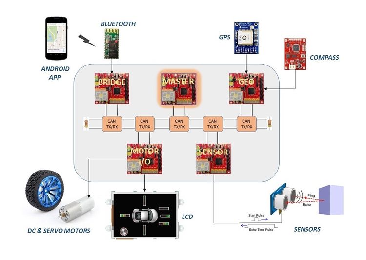
The GPS-controlled automated RC car will consistes of 5 different LPC 1758 controllers. Each controller will have a specific major tasks required to drive the car. The naming convention goes as:- Motor & I/O controller - this will control the motors of the car and will also connected with a LCD display to show the car's status, Sensor controller - It will be connected to the obstacle detecting sensors on the car, Communication Bridge - It will be connected to an Android mobile phone so as to provide co-ordinates, GEO controller - This will give the exact orientation of the car e.g., heading & bearing, etc. and finally the Master controller - This will collect the data from other controllers and will guide the motor controller. These controllers are connected using CAN bus. After the final implementation, this car will be capable of driving by itself using the destination co-ordinates set by us avoiding every obstacles, overcoming slopes thereby reaching the destination safely!
Objectives & Introduction
Show list of your objectives. This section includes the high level details of your project. You can write about the various sensors or peripherals you used to get your project completed.
Team Members & Responsibilities
Treasurer:
- Anuj Korat
Five Controllers Used
- Master Controller
- Motor I/O Controller
- Sensor Controller
- Geographical Controller
- Bluetooth/Bridge Controller
Schedule
Show a simple table or figures that show your scheduled as planned before you started working on the project. Then in another table column, write down the actual schedule so that readers can see the planned vs. actual goals. The point of the schedule is for readers to assess how to pace themselves if they are doing a similar project.
Team Schedule
| SI No. | Start Date | End Date | Task | Status | Actual Completion Date |
|---|---|---|---|---|---|
| 1 | 09/15/2015 | 09/27/2015 |
|
Completed | 09/27/2015 |
| 2 | 09/27/2015 | 10/30/2015 | Following up on RC car and other component procurement through team discussions | Completed | 10/30/2015 |
| 3 | 10/30/2015 | 10/06/2015 | Hardware design of the car including discussions on component placement, soldering and wiring. | Completed | 10/06/2015 |
| 4 | 10/06/2015 | 10/17/2015 | CAN message ID's, priorities, data size and format proposals for all the possible CAN messages on the bus | Completed | 10/20/2015 |
| 5 | 10/20/2015 | 11/05/2015 | Discussions and proposals on basic obstacle avoidance algorithm with sensor integration, hands on and testing | Completed | 11/03/2015 |
| 6 | 11/05/2015 | 11/25/2015 | Integrating other modules and components to the RC car, development of autonomous driving algorithm and finalize on hardware layout of the car | Completed | 12/1/2015 |
| 7 | 11/25/2015 | 12/7/2015 | Testing the RC car in real world environments | Completed | 12/5/2015 |
Parts List & Cost
Design & Implementation
The design section can go over your hardware and software design. Organize this section using sub-sections that go over your design and implementation.
DBC File Implementation
- This section explains DBC file implementation of the project. The DBC implementation contains the python based DBC file parser, a DBC file and auto generated C code for the five CAN nodes. These five nodes include driver(master), sensor, motor, geo and bluetooth node. The DBC file is a input to the python DBC parser script. The python script will generate a C file for the specific node given by the user at the command line argument. The python script goes through this DBC file and generates code to marshal (covert to raw CAN) and unmarshal (convert from raw CAN) using the provided API that you can enclose in a header file.
- The following is the DBC file of the project.
     VERSION ""
      NS_ :
           NS_DESC_
           CM_
           BA_DEF_
           BA_
           VAL_
           CAT_DEF_
           CAT_
           FILTER
           BA_DEF_DEF_
           EV_DATA_
           ENVVAR_DATA_
           SGTYPE_
           SGTYPE_VAL_
           BA_DEF_SGTYPE_
           BA_SGTYPE_
           SIG_TYPE_REF_
           VAL_TABLE_
           SIG_GROUP_
           SIG_VALTYPE_
           SIGTYPE_VALTYPE_
           BO_TX_BU_
           BA_DEF_REL_
           BA_REL_
           BA_DEF_DEF_REL_
           BU_SG_REL_
           BU_EV_REL_
           BU_BO_REL_
           SG_MUL_VAL_
BS_:
BU_: NOONE SENSOR DRIVER MOTORIO BLUETOOTH GEO
BO_ 0 DRIVER_KILL_SWITCH: 0 DRIVER
 SG_ DRIVER_KILL_SWITCH_cmd 		: 0|0@1+ (1,0) [0|0] "" SENSOR,MOTORIO,BLUETOOTH,GEO
BO_ 1 DRIVER_RESET: 0 DRIVER
 SG_ DRIVER_RESET_cmd 				: 0|0@1+ (1,0) [0|0] "" SENSOR,MOTORIO,BLUETOOTH,GEO
BO_ 2 DRIVER_SYNC_ACK: 0 DRIVER
 SG_ DRIVER_SYNC_ACK_cmd 			: 0|0@1+ (1,0) [0|0] "" SENSOR,MOTORIO,BLUETOOTH,GEO
BO_ 3 MOTORIO_SYNC: 0 MOTORIO
 SG_ MOTORIO_SYNC_cmd 				: 0|0@1+ (1,0) [0|0] "" DRIVER
BO_ 4 SENSOR_SYNC: 0 SENSOR
 SG_ SENSOR_SYNC_cmd 				: 0|0@1+ (1,0) [0|0] "" DRIVER
BO_ 5 BLUETOOTH_SYNC: 0 BLUETOOTH
 SG_ BLUETOOTH_SYNC_cmd 			: 0|0@1+ (1,0) [0|0] "" DRIVER
BO_ 6 GEO_SYNC: 0 GEO
 SG_ GEO_SYNC_cmd 					: 0|0@1+ (1,0) [0|0] "" DRIVER
BO_ 7 MOTORIO_HEARTBEAT: 0 MOTORIO
 SG_ MOTORIO_HEARTBEAT_cmd 			: 0|0@1+ (1,0) [0|0] "" DRIVER
BO_ 8 SENSOR_HEARTBEAT: 0 SENSOR
 SG_ SENSOR_HEARTBEAT_cmd 			: 0|0@1+ (1,0) [0|0] "" DRIVER
BO_ 9 BLUETOOTH_HEARTBEAT: 0 BLUETOOTH
 SG_ BLUETOOTH_HEARTBEAT_cmd 		: 0|0@1+ (1,0) [0|0] "" DRIVER
BO_ 10 GEO_HEARTBEAT: 0 GEO
 SG_ GEO_HEARTBEAT_cmd 				: 0|0@1+ (1,0) [0|0] "" DRIVER
BO_ 11 MOTORIO_RUNMODE: 1 DRIVER
 SG_ MOTORIO_RUNMODE_cmd 			: 0|8@1+ (1,0) [0|3] "" MOTORIO
BO_ 12 SENSOR_SONARS: 6 SENSOR
 SG_ SENSOR_SONARS_front_left 		: 0|8@1+ (1,0) [0|4] "" DRIVER,MOTORIO
 SG_ SENSOR_SONARS_front_right 		: 8|8@1+ (1,0) [0|4] "" DRIVER,MOTORIO
 SG_ SENSOR_SONARS_front_center 	: 16|8@1+ (1,0) [0|4] "" DRIVER,MOTORIO
 SG_ SENSOR_SONARS_left 			: 24|8@1+ (1,0) [0|4] "" DRIVER,MOTORIO
 SG_ SENSOR_SONARS_right 			: 32|8@1+ (1,0) [0|4] "" DRIVER,MOTORIO
 SG_ SENSOR_SONARS_back 			: 40|8@1+ (1,0) [0|4] "" DRIVER,MOTORIO
BO_ 13 MOTORIO_DIRECTION: 2 DRIVER
 SG_ MOTORIO_DIRECTION_speed_cmd 	: 0|8@1+ (1,0) [0|4] "" MOTORIO
 SG_ MOTORIO_DIRECTION_turn_cmd 	: 8|8@1+ (1,0) [0|5] "" MOTORIO
BO_ 14 DRIVER_CHECKPOINT_REQ: 1 DRIVER
 SG_ DRIVER_CHECKPOINT_REQ_cmd 		: 0|8@1+ (1,0) [0|3] "" BLUETOOTH,MOTORIO
BO_ 15 BLUETOOTH_CHECKPOINT_SEND: 1 BLUETOOTH
 SG_ BLUETOOTH_CHECKPOINT_SEND_cmd 	: 0|8@1+ (1,0) [0|3] "" DRIVER,MOTORIO
BO_ 16 BLUETOOTH_CHECKPOINT_DATA: 1 BLUETOOTH
 SG_ BLUETOOTH_CHECKPOINT_DATA_cmd 	: 0|8@1+ (1,0) [0|3] "" DRIVER,MOTORIO
BO_ 17 DRIVER_LOC_UPDATE: 8 DRIVER
 SG_ DRIVER_LOC_UPDATE_LAT_cmd 		: 0|32@1+ (0.0001,0) [0|0] "" GEO,MOTORIO
 SG_ DRIVER_LOC_UPDATE_LONG_cmd 	: 32|32@1+ (0.0001,0) [0|0] "" GEO,MOTORIO
BO_ 18 GEO_SPEED_ANGLE: 5 GEO
 SG_ GEO_SPEED_cmd 					: 0|8@1+ (1,0) [0|0] "" DRIVER,MOTORIO
 SG_ GEO_ANGLE_heading_cmd 			: 8|16@1+ (1,0) [0|0] "" DRIVER,MOTORIO
 SG_ GEO_ANGLE_bearing_cmd 			: 24|16@1+ (1,0) [0|0] "" DRIVER,MOTORIO
BO_ 19 GEO_LOC_DATA: 8 GEO
 SG_ GEO_LOC_LAT_cmd 				: 0|32@1+ (0.0001,0) [0|0] "" DRIVER,MOTORIO
 SG_ GEO_LOC_LONG_cmd 				: 32|32@1+ (0.0001,0) [0|0] "" DRIVER,MOTORIO
BO_ 20 SENSOR_LIGHT_BAT: 2 SENSOR
 SG_ SENSOR_LIGHT_cmd 				: 0|8@1+ (1,0) [0|1] "" DRIVER,MOTORIO
 SG_ SENSOR_BAT_cmd 				: 8|8@1+ (1,0) [0|1] "" DRIVER,MOTORIO
CM_ BU_ NOONE "No node, used to indicate if it's a debug message going to no one";
CM_ BU_ DRIVER "The driver controller driving the car";
CM_ BU_ SENSOR "The sensor controller of the car";
CM_ BU_ MOTORIO "The motor_io controller of the car";
CM_ BU_ BLUETOOTH "The bluetooth controller of the car";
CM_ BU_ GEO "The geo controller of the car";
CM_ BO_ 2 "Sync message used to synchronize the controllers";
BA_DEF_  "BusType" STRING ;
BA_DEF_ SG_ "FieldType" STRING ;
BA_DEF_ BO_ "GenMsgCycleTime" INT 0 0;
BA_DEF_DEF_ "BusType" "CAN";
BA_DEF_DEF_ "FieldType" "";
BA_ "GenMsgCycleTime" BO_ 7 	          1;
BA_ "GenMsgCycleTime" BO_ 8 	          1;
BA_ "GenMsgCycleTime" BO_ 9 	          1;
BA_ "GenMsgCycleTime" BO_ 10              1;
BA_ "GenMsgCycleTime" BO_ 11 	          1;
BA_ "GenMsgCycleTime" BO_ 12              10;
BA_ "GenMsgCycleTime" BO_ 13              10;
BA_ "GenMsgCycleTime" BO_ 17              10;
BA_ "GenMsgCycleTime" BO_ 18              10;
BA_ "GenMsgCycleTime" BO_ 19              10;
- Let's understand the above DBC file. The line which contains BU_:... tells the python parser that the user has five nodes in the CAN implementation. In the TopGun project, we have total five nodes -> SENSOR, DRIVER(master), MOTOR, BLUETOOTH, GEO.
- The second important thing in the DBC file is the lines starting from BO_ message_id. These lines define the different message ids for the CAN implementation of the TopGun project. Here, the project includes total 20 message ids. So, The DBC file contains separate BO_ message_id line for each and every message id. Now, let's see what these lines are indicating to the python parser. What the BO_ line contains is given below:
- BO_ 4 SENSOR_SYNC: 0 SENSOR --> BO_ "message_id" "message_id_name" "number_of_bytes_transmitted_on_CANbus" "transmitter_node"
- Now, there are lines which start from SG_. The format of the line contains SG_ is given below. It will contain the variable name that we want to marshal and unmarshal for the CAN bus message data. It also contains the size of that variable and from where it is placed in the 8 bytes of total data. This line will also decide the range of the value held by this variable. User needs to define this max and mim range according to the application. If it is [0|0], then the the parser will consider this as a default and will give the maximum and minimum value of that variable according to its size and the sign information of the variable. Information in the (1,0) will define the multiplier of the value of the variable which in this case is 1. The second value of this bracket is 0 which indicates the offset for the value of the variable.
- Execute the following commands in the command line argument to generate the API for the motor controller node.
- $python dbc_parse.py -i TopGun_12_38am_11_16_2015.dbc -s MOTORIO > generated_code_MOTORIO.c
- The above command will generate the code for the generated_code_MOTORIO.c file
Describe the challenges of your project. What advise would you give yourself or someone else if your project can be started from scratch again? Make a smooth transition to testing section and described what it took to test your project.
CAN Message ID Table
| Message ID | Task associated with ID | Data bit-fields |
|---|---|---|
| 0x00 | Kill Switch | No Data |
| 0x01 | Reset |
reset_motorio:8; // Acknowledge motorio controller reset_sensor:8; // Acknowledge sensor controller reset_geo:8; // Acknowledge geo controller reset_bluetooth:8; // Acknowledge bluetooth module |
| 0x02 | Master Sync Ack |
ack_motorio:8; // Acknowledge motorio controller ack_sensor:8; // Acknowledge sensor controller ack_geo:8; // Acknowledge geo controller ack_bluetooth:8; // Acknowledge bluetooth module |
| 0x03 | MotorIO Controller Sync | No Data |
| 0x04 | Sensor Controller Sync | No Data |
| 0x05 | Bluetooth Controller Sync | No Data |
| 0x06 | Geo Controller Sync | No Data |
| 0x07 | MotorIO controller Heart-beat | No Data |
| 0x08 | Sensor controller Heart-beat | No Data |
| 0x09 | Bluetooth controller Heart-beat | No Data |
| 0x0A | Geo controller Heart-beat | No Data |
| 0x0B | Run mode | mode:8; |
| 0x0C | Distance Sensor Data |
front_left:8; // Front left sensor reading front_right:8; // Front right sensor reading front_center:8; // Front centre sensor reading left:8; // Left sensor reading right:8; // Right sensor reading back:8; // Back sensor reading |
| 0x0D | MotorIO Direction Data |
speed:8; // Indicate speed for DC motor turn:8; // Indicate turn angle for servo motor |
| 0x0E | Check-point Request Message | No Data |
| 0x0F | Check-point Start Message |
num_of_points; // Number of check-points to be loaded |
| 0x10 | Check-point Data |
float latitude; float longitude; |
| 0x11 | Geo-Controller New Destination Data |
float latitude; float longitude; |
| 0x12 | Geo-Controller Speed and Angle message |
speed:8; // Speed as measured by the GPS sensor heading:16; // Heading from the Geo controller bearing:16; // Bearing calculated by the Geo controller |
| 0x13 | Geo-Controller Location Data |
float latitude; float longitude; |
| 0x14 | Light and Battery Sensor Data |
light_sensor:8; // Light sensor reading batt_sensor:8; // Battery level sensor reading |
Sensor Controller
Team Members:
Divya Dodda
Dhruv Kakadiya
Sensor Controller Schedule
| SI No. | Start Date | End Date | Task | Status | Actual Completion Date |
|---|---|---|---|---|---|
| 1 | 09/20/2015 | 09/27/2015 | Researching and ordering the sensors to be used in the project | Completed | 9/27/2015 |
| 2 | 09/27/2015 | 10/03/2015 |
|
Completed | 10/03/2015 |
| 3 | 10/03/2015 | 10/10/2015 | Interfacing ADC ultrasonic sensor to SJOne board, reading sensor values and filter the readings | Completed | 10/10/2015 |
| 4 | 10/10/2015 | 10/20/2015 | Understanding inertial measurement unit sensor, interfacing it to SJOne board to get filtered readings | Completed | 10/20/2015 |
| 5 | 10/20/2015 | 11/05/2015 | Integrating multiple sensors to the SJOne board, testing the sensors and debugging issues | Completed | 11/02/2015 |
| 6 | 11/05/2015 | 11/15/2015 | Preparing sensor values to be sent over CAN bus and testing out the correctness of sensor can messages | Completed | 11/10/2015 |
| 7 | 11/25/2015 | 11/30/2015 | Testing of code during final phases, modifying code in cooperation with other teams and optimization of code | Completed | 12/1/2015 |
Sensor Testing
Simple Sensor ping operation
HCSR04 Sensor Testing
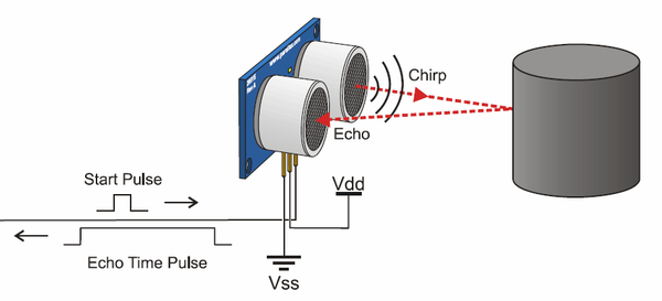
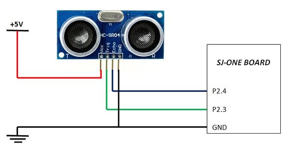
- As shown in the figure below, HC-SR04 ultrasonic sensor requires an external 5V DC supply.
- When in the initial testing stage we just connected one sensor for testing the accuracy and the range of the sensor.
- The values we received were very stable and neat.
Parallax Ping Sensor Testing
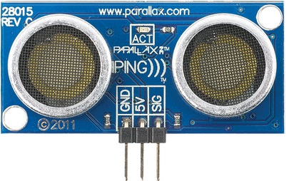
- As shown in the figure below, Parallax ping ultrasonic sensor requires an external 5V DC supply.
Finalizing distance sensors
- Both sensors being pretty accurate, we were confused while finalizing one. So we were using both sensors, for front we were using Parallax and for left,right and back sensors we were using HCSR04 sensor.
- HCSR04 sensor was better option because as it was much cost efficient than the Parallax Ping Sensor (Where one Parallax Ping costs $30, one HCSR04 costed us only $2)
- Its only drawback is, the cheaper one sensor needed good filter to remove some spikes and Parallax sensor was working pretty good without any filtering.
Switching to Hardware Timer
- Previously, all sensor were triggered using software timers. We declared a soft timer for each sensor which kept track of the time between trigger and echo for that particular sensor.
- If we see the declaration of software timer as shown below, we come to know that the timer returns a value in milliseconds.
   SoftTimer limit_time;
   limit_time.reset(25);
   limit_time.restart();
   if(limit_time.expired()){
       break;
   }
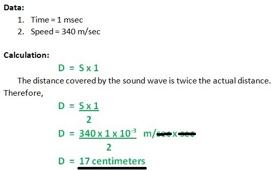
- If we apply the before mentioned distance formula to this timer value in milliseconds, we will always get the distance in multiples of 17.
- Let's work out an example for better understanding;
- As the return return type of this function is an integer, we always get the distance in multiples of 17, which compromises the accuracy by a large factor.
- Because of this reason we switched to hardware timers.
- The declaration of hardware timer is as shown below, and this return value of time is in micro-seconds.
   lpc_timer_enable(lpc_timer0,1);
   lpc_timer_set_value(lpc_timer0,0);
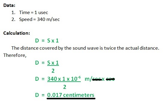
- Let's work out the same example for the return value being 1usec.
- Hence, even if the timer value is an integer, as it is in microseconds, we have improved the accuracy.
- As there are only three hardware timers in LPC 1768 we cannot allot individual timer for each sensor. Hence, we use just one hardware timer which runs regardless any individual sensor.
- All sensors get the current timer value during trigger and echo from this single timer, and do the further processing individually.
Sequentially Triggering of Sensors
- We used to trigger all the sensors at the same time, which caused interference between adjacent sensors, which in turn caused mis-firing of echo.
- This resulted in incorrect distance values from all the sensors.
- Thus to solve this issue, we implemented sequential triggering.
- Under this logic, each sensor will be triggered only when the previous sensor receives an echo or exceeds the maximum echo reception wait time which is 60msec.
- This implementation solved the issue at hand but gave rise to a new issue which is mentioned in the next section.
Limiting the Scope to Improve Frequency
- As discussed in the previous section, if we implement sequential triggering for each sensor, if there is no obstacle, then the worst case delay would be 360 msec(60msec*6sensors) to update all sensor values to the master.
- Means the frequency of communicating these values to the master will be, 2.8Hz.
- For proper obstacle avoidance, we need to provide the sensor data to the master atleast 10 times per second, i.e. at 10Hz.
- Which means data from all six sensors must be calculated within 100msec.
- Even if we consider limiting the time allotted to a sensor to time required for maximum distance (400cms), we will require 23.5msec each sensor i.e. 141msec to update the values of all six sensors. This increases the frequency to 7.1Hz.
- This led is to the solution to this problem, if we limit the scope of each sensor then we can update the sensor values more frequently to the master.
- To overcome this issue, we limited the maximum scope of the sensor to 170 cms, limiting the time required to get the echo to 10msec. Which makes the total time required to calculate all six sensors' data about 60msec.
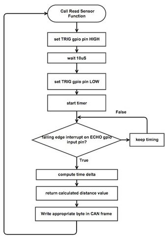
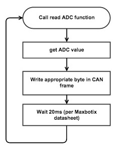
- Hence, as shown in the flowchart, each sensor waits 10msec for an echo. If we get an echo within 10msec, we calculate the distance; if we don't, we assume the obstacle is at 170cms or further.
Misfiring of Sensor
- At times the sensor used to mis-fire. Which means; in a stable condition, if the obstacle is at a constant distance of 150cms, 1 out of 50 continuous values will be 60cms.
- This value being false, misguides the master.
- To overcome this issue, we introduced a threshold value called DELTA (say, 10cms). Which defines the acceptable range from the previous value.
- In this algorithm, an abrupt change in the distance value should be constant for at least two consecutive reads to be considered genuine.
- If the current value from the sensor is in the range of the previous value's +/- 10cms, then this value is considered to be correct, and is provided to the master. Then this current value will be copied in the previous value register.
- If the current value is not is the previous value's +/- DELTA range then it is considered as a misfire and hence is not provided to the master. But this sudden change might be because of a sudden obstacle; hence, the value is copied in the previous value register, and if the same value repeats, it will be considered genuine and provided to the master.
- The code for this algorithm is as shown below;
       if(temp-DELTA<current && current<temp+DELTA){
           distance = current;
       }
       temp = current;
- Hence, this algorithm will overcome the abrupt mis-firing of the sensor and make the data provided to the master more reliable.
Sensor Software Design
Sensor Controller Team Software Design
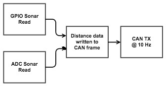
- Sensor software design is composed of three crucial tasks, which are to read GPIO based sonar, read ADC based sonar, and CAN TX.
Operation Sequences
Tasks
| Task Name | Purpose |
|---|---|
| Period Init | Can bus initialization |
| Period Register telemetry | Register sensor_data can message |
| Periodic 1Hz Callback | Check can bus off |
| Periodic 10Hz Callback | Get and Send Sensor Data |
Sensor Pin Connections
| Line Item# | Node A Source | Node A Pin | Node B Source | Node B Pin | Description |
|---|---|---|---|---|---|
| 1 | 3.3V Power Supply | 3.3V | SJOne Board | 3V3 | SJOne Power |
| 2 | 3.3V Power Supply | GND | SJOne Board | GND | SJOne Ground |
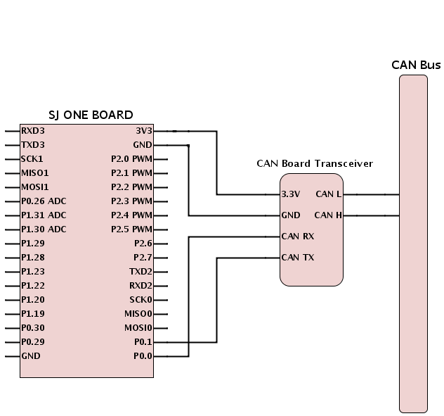
| 3 | CAN Transceiver | Tx | SJOne Board | P0.1 (Tx) | SJOne - CAN Tx |
| 4 | CAN Transceiver | Rx | SJOne Board | P0.0 (Rx) | SJOne - CAN Rx |
| 5 | CAN Transceiver | 3.3V | 3.3V Power Supply | 3.3V | SJOne - CAN Power |
| 6 | CAN Transceiver | Ground | 3.3V Power Supply | GND | SJOne - CAN Ground |
| 7 | Parallax Ultrasonic Sensor (Front Left) | Vcc | 5V Power Supply | +5V | Front Left Sensor Power |
| 8 | Parallax Ultrasonic Sensor (Front Left) | GND | 5V Power Supply | GND | Front Left Sensor GND |
| 9 | Parallax Ultrasonic Sensor (Front Left) | Echo/Trig | SJOne Board | P2.0 | Front Left Sensor Echo |
| 10 | Parallax Ultrasonic Sensor (Front Right) | Vcc | 5V Power Supply | +5V | Front Right Sensor Power |
| 11 | Parallax Ultrasonic Sensor (Front Right) | GND | 5V Power Supply | GND | Front Right Sensor GND |
| 12 | Parallax Ultrasonic Sensor (Front Right) | Echo/Trig | SJOne Board | P2.2 | Front Right Sensor Echo |
| 13 | Parallax Ultrasonic Range Sensor (Front Middle) | Vcc | 5V Power Supply | +5V | Front Middle Sensor Power |
| 14 | Parallax Ultrasonic Range Sensor (Front Middle) | GND | 5V Power Supply | GND | Front Middle Sensor GND |
| 15 | Parallax Ultrasonic Range Sensor (Front Middle) | Echo | SJOne Board | P2.4 | Front Middle Sensor Echo |
| 16 | Parallax Ultrasonic Range Sensor (Front Middle) | Trig | SJOne Board | P2.5 | Front Middle Sensor Trig |
| 17 | HC-SR04 Ultrasonic Sensor (Left) | Vcc | 5V Power Supply | +5V | Left Sensor Power |
| 18 | HC-SR04 Ultrasonic Sensor (Left) | GND | 5V Power Supply | GND | Left Sensor GND |
| 19 | HC-SR04 Ultrasonic Sensor (Left) | Echo | SJOne Board | P2.6 | Left Sensor Echo |
| 20 | HC-SR04 Ultrasonic Sensor (Left) | Trig | SJOne Board | P2.7 | Left Sensor Trig |
| 21 | HC-SR04 Ultrasonic Sensor (Right) | Vcc | 5V Power Supply | +5V | Right Sensor Power |
| 22 | HC-SR04 Ultrasonic Sensor (Right) | GND | 5V Power Supply | GND | Right Sensor GND |
| 23 | HC-SR04 Ultrasonic Sensor (Right) | Echo | SJOne Board | P2.8 | Right Sensor Echo |
| 24 | HC-SR04 Ultrasonic Sensor (Right) | Trig | SJOne Board | P2.9 | Right Sensor Trig |
| 25 | CAN Transceiver | CANL | CAN BUS | CANL | CANL to CAN BUS |
| 26 | CAN Transceiver | CANR | CAN BUS | CANR | CANR to CAN BUS |
Geographical Controller
Team Members:
Chitrang Talaviya
Navjot Singh
Geographical Controller Schedule
| SI No. | Start Date | End Date | Task | Status | Actual Completion Date |
|---|---|---|---|---|---|
| 1 | 09/20/2015 | 09/27/2015 | Researching and ordering the parts | Completed | 9/27/2015 |
| 2 | 09/27/2015 | 10/05/2015 | Studying module data sheets and writing code sketches to be used when modules are procured(GPS and IMU) | Completed | 10/05/2015 |
| 3 | 10/05/2015 | 10/15/2015 | Interfacing GPS module and compass to SJOne board and get consistent filtered readings | Completed | 10/17/2015 |
| 4 | 10/15/2015 | 10/30/2015 | Proposals for heading and distance calculation, unit testing and integrating modules | Completed | 10/30/2015 |
| 5 | 10/30/2015 | 11/10/2015 | Calibration of compass and GPS readings, CAN bus communication from geo controller to other boards. | Completed | 11/10/2015 |
| 6 | 11/10/2015 | 11/25/2015 | Android application connection with data reception and transmit | Completed | 11/25/2015 |
| 7 | 11/25/2015 | 12/15/2015 | Final phase testing and optimization, collaborating with android team to get better reliable outcomes | Completed | 12/12/2015 |
Geographical Controller H/W Design
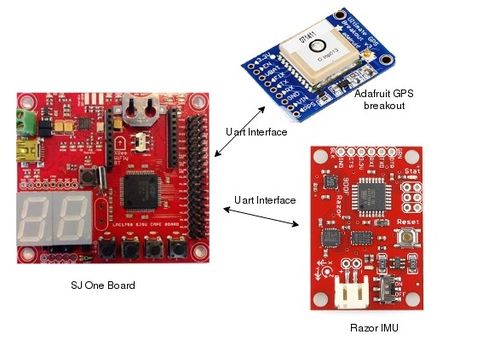
- Below figure represents the block diagram of Geo Controller. Geo-controller uses GPS and IMU module for its working. Uart3 and Uart2 are used for interfacing IMU and GPS with SJ One board at baud rate 9600bps.
Geographical Controller H/W Interface
- Below table shows the Pins connection of GPS and IMU module with SJ One Board. Both the h/w's are interfaced with Controller using UART interface. The operating volatge of GPS and IMU is 3.3V.
| Description | Interface | Device Port | SJOne Board Port |
|---|---|---|---|
| Supply Voltage | N/A | Vcc | 3.3 V |
| Ground | N/A | GND | GND |
| GPS Module | UART2 |
Channel 1 -> Rx Channel 2 -> Tx Channel 3 -> EN |
Channel 1 -> Tx P2.8 Channel 2 -> Rx P2.9 Channel 3 -> Vcc |
| IMU Module | UART3 |
Channel 1 -> Rx Channel 2 -> Tx Channel 3 -> DTR |
Channel 1 -> Tx P4.28 Channel 2 -> Rx P4.29 Channel 3 -> GPIO P2.2 |
Geographical Controller S/W Design
Geographical controller uses two modules to get GPS data and headings. These are:
- GPS module
- IMU module
In the below sections, one will see the methods used to get the values from the modules. Both of the modules are interfaced using UART.
- GPS:-
- Initialization: In Progress
- Getting Data from Module:
- Sending data over CAN bus
- IMU:
- Initialization:
- Getting data from IMU module:
- Sending data over CAN bus:
- Updating Firmware on IMU:
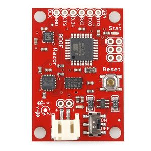
- For updating the firmware on IMU, we used FTDI basic breakout which uses USB mini cable to connect to PC. The board comes programmed with the 8MHz Arduino bootloader (stk500v1) and some example firmware that demos the outputs of all the sensors. UART connection are made to interface IMu with breakout board at 57600bps.
- Connections between IMU and FTDI breakout :-
FTDI BREAKOUT      RAZOR
GND           <--> GND
CTS           <--> CTS
3.3V          <--> 3.3V
TXO           <--> RXI
RXI           <--> TXO
DTR           <--> DTR
The details are given at: https://github.com/ptrbrtz/razor-9dof-ahrs/wiki/Tutorial. Firmware provides the readings Yaw, Pitch and Roll readings. As in the project we only need the Yaw data, so firmware is been updated to provide only the Yaw readings.
- Sensor Calibration:
- Sensor calibration include calibrating the accelerometer, gyroscope and magnetometer. Sensor calibration in our project is done twice, once in the beginning and then at the end when all the boards are mounted on the car. As the magnetic field of motor can effect the gyroscope readings so we did the calibration again. The details can be found on the link given above.
Geographical Controller Hardware Design Components
|
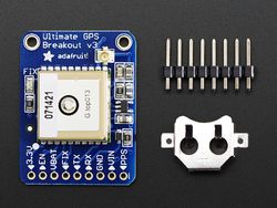
Adafruit MTK3339 GPS: This GPS unit is interfaced via UART with build in antenna. The GPS provides latitude and longitude accurately up to 5-10 meters with a strong satellite fix with update rate of 10Hz. By default, the baud rate is 9600bps. Power usage for this module is 20mA during navigation. The GPS module comes with following capabilities:
We chose this part because it provided the base functionality we needed along with many other functions that would be fun to play with and try to include in the project. The antennae options and voltage regulator were also very enticing. We gets raw GPS "NMEA sentence" output from module. The most important NMEA sentences include the GGA which provides the current Fix data, the RMC which provides the minimum gps sentences information, and the GSA which provides the Satellite status data. We are filtering the data for RMC, Recommended Minimum, which will look similar to: $GPRMC,123519,A,4807.038,N,01131.000,E,022.4,084.4,230394,003.1,W*6A
where:-RMC Recommended Minimum sentence C
123519 Fix taken at 12:35:19 UTC
A Status A=active or V=Void.
4807.038,N Latitude 48 deg 07.038' N
01131.000,E Longitude 11 deg 31.000' E
022.4 Speed over the ground in knots
084.4 Track angle in degrees True
230394 Date - 23rd of March 1994
003.1,W Magnetic Variation
*6A The checksum data, always begins with *
|
||
|
9 Degrees of Freedom- Razor IMU: In our project, we used IMU module to get the heading of the device. The 9DOF Razor IMU provides nine degree of inertial measurement by incorporates three sensors - an ITG-3200 (MEMS triple-axis gyro), ADXL345 (triple-axis accelerometer), and HMC5883L (triple-axis magnetometer).The outputs of all sensors are processed by an on-board ATmega328 and output over a serial interface. UART interface is used for interfacing with SJ One board and it is connected via UART3 with LPC board and is operated at 3.3V. Features:
|
Motor I/O Controller
Team Members:
Anuj Korat
Dhruv Kakadiya
Motor & I/O Controller Schedule
| SI No. | Start Date | End Date | Task | Status | Actual Completion Date |
|---|---|---|---|---|---|
| 1 | 09/20/2015 | 09/27/2015 | Researching and ordering the LCD module to be used in the project | Completed | 9/27/2015 |
| 2 | 09/27/2015 | 10/05/2015 |
|
Completed | 10/05/2015 |
| 3 | 10/05/2015 | 10/12/2015 |
|
Completed | 10/12/2015 |
| 4 | 10/12/2015 | 10/30/2015 |
|
Completed | 11/5/2015 |
| 5 | 10/30/2015 | 11/12/2015 | Proposals related to speed controls and sensors for the same and integration of LCD module(with data display) | Completed | 11/12/2015 |
| 6 | 11/12/2015 | 11/25/2015 | CAN bus communication from motor and I/O controller to other boards | Completed | 11/15/2015 |
| 7 | 11/25/2015 | 12/15/2015 | Debugging issues during trial runs and testing out fault cases | Completed | 12/8/2015 |
Motor/IO Controller Software Design
DC Motor
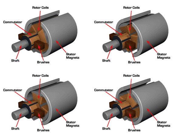
|
Our car came installed with the motor which needs 7.4V of power supply to work. This motor has the power to run the car at the maximum speed of the 35mph.
Table3: DC Motor Duty Cycle v/s Speed |
|
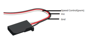
DC motor is controlled with the help of three wires coming out of the ESC. The wires are Vcc, Gnd and Speed control. The Vcc is not used as required voltage is directly given to motor through battery via ESC. The Gnd is connected with Gnd pin and Speed control is connected to the PWM pin of SJOne board.
DC Motor Pin Connections For DC motor we are using pwm2 i.e. pin P2.1 of the SJOne board, the pwm function is the in-build function which requires two parameters, one is pwm that we are using and the second parameter is the frequency of the pwm. To set the duty cycle in-build set function is used in which we are passing the duty cycle at which we want DC motor to work. |
Servo Motor
|
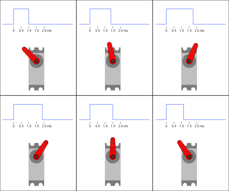
Our car came with waterproof digital servo motor. This motor works without ESC. We can directly control this motor by giving PWM signal from our SJOne board. The below table contains information about PWM (duty cycle) given to the motor and the corresponding turns taken by the car.
Servo Motor Duty Cycle v/s Turn |
|
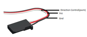
Servo motor is controlled with the help of three wires coming out of the servo motor. The wires are Vcc, Gnd and Direction control. The Vcc is connected to the 3.3v, Gnd is connected with Gnd pin and direction control is connected to the pwm pin of SJOne board.
Servo Motor Pin Connections For Servo motor we are using pwm1 i.e. pin P2.0 of the SJOne board, the pwm function is the in-build function which requires two parameters, one is pwm that we are using and the second parameter is the frequency of the pwm. To set the duty cycle in-build set function is used in which we are passing the duty cycle at which we want servo motor to work. |
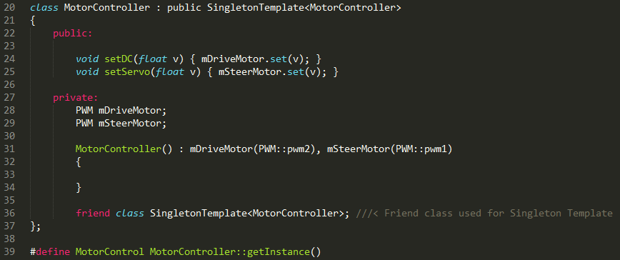
Motor PWM Singleton implementation
I/O Software Design
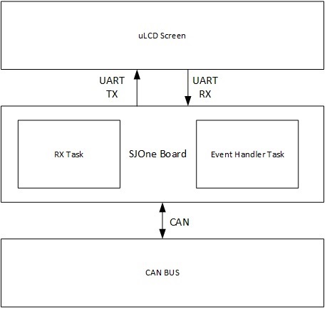
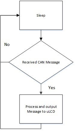
The I/O Software is based off of two tasks: The Event Handler Task and the RX Task.
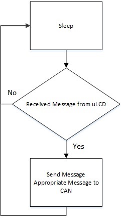
Event Handler Task (High Priority):
This Task receives any immediate messages sent from the uLCD, processes the message, and sends the message to the CAN BUS.
This task enables the system to: Turn On/Off the Vehicle and Change Vehicle Modes.
RX Task (Low Priority):
This task receives all messages from the CAN BUS, and outputs message data onto the uLCD
High Level IO Software Logic -- Event Handler Task Logic -- RX Task Logic
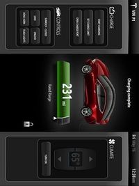
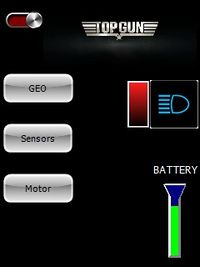
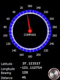
Different screens on LCD
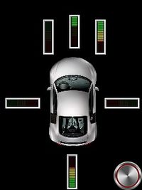
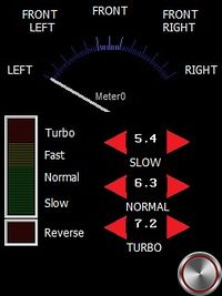
The Displays on LCD were well thought of according to its application in our project. We wanted to test the sensor and the magnetometer readings while we were testing out car along with testing the algorithm of navigation. This would enable us to not connect the LPC controller with a Laptop to check any readings. The LCD we bought is from 4D systems and is very convenient and efficient to use. It has its own software which enables us to work in 4 different modes. We chose the mode which gave us different tools to build the compass, buttons and the angularometer. A bluetooth to serial converter is used to program the LCD with the software. After we had used the tools on to picturize our LCD screens. We burned the program down to LCD's memory card. The program that we burned on LCD will use the data bytes we send from our microcontroller and will print those bytes appropriately on different elements that we had created. For example, there are 360 degrees values to show on angularometer. The microcontroller will give a value from 0-360 based on the CAN frame which consists of car speed, heading and bearing values broadcasted by the Geo controller. In this way each and every item is driven.
Master Controller
Team Members:
Hemanth Konanur Nagendra
Akshay Vijaykumar
Master Controller Schedule
| SI No. | Start Date | End Date | Task | Status | Actual Completion Date |
|---|---|---|---|---|---|
| 1 | 10/10/2015 | 10/20/2015 |
|
Completed | 10/20/2015 |
| 2 | 10/21/2015 | 10/31/2015 |
|
Completed | 10/25/2015 |
| 3 | 10/26/2015 | 11/01/2015 |
|
Completed | 11/01/2015 |
| 4 | 11/10/2015 | 11/20/2015 |
|
Completed | 11/20/2015 |
| 5 | 10/21/2015 | 11/30/2015 |
|
Completed | 11/24/2015 |
| 6 | 12/01/2015 | 12/07/2015 |
|
Completed | 12/12/2015 |
| 7 | 12/08/2015 | 12/15/2015 | Extensive testing and smoothing out speed, turning, etc | In Progress |
The Master Controller receives obstacle information from the Sensor Controller, navigation data from the Geo Controller and routing information from the Bluetooth Controller, collates all this information and provides driving directions to the Motor Controller.
Design
Master Controller Team Hardware Design
Master Pin Connections
| Line Item# | Node A Source | Node A Pin | Node B Source | Node B Pin | Description |
|---|---|---|---|---|---|
| 1 | 3.3V Power Supply | 3.3V | SJOne Board | 3V3 | SJOne Power |
| 2 | 3.3V Power Supply | GND | SJOne Board | GND | SJOne Ground |
| 3 | CAN Transceiver | CAN Tx | SJOne Board | P0.1 (Tx) | SJOne - CAN Tx |
| 4 | CAN Transceiver | CAN Rx | SJOne Board | P0.0 (Rx) | SJOne - CAN Rx |
| 5 | CAN Transceiver | CAN 3.3V | 3.3V Power Supply | 3.3V | SJOne - CAN Power |
| 6 | CAN Transceiver | CAN Ground | 3.3V Power Supply | GND | SJOne - CAN Ground |
| 7 | CAN Transceiver | CANL | CAN BUS | CANL | CANL to CAN BUS |
| 8 | CAN Transceiver | CANR | CAN BUS | CANR | CANR to CAN BUS |
Control Flow
On boot-up, Master Controller first attempts to sync with all the other controllers through a power-up sync and acknowledgement handshake mechanism. Once sync is established with all the controllers, it periodically monitors the heart-beat signals from all the controllers till the end of power cycle. If any controller goes out of sync, the master requests that controller to reset itself.
The Master Controller now enters the ‘stopped’ state where no driving takes place. It continuously monitors the CAN bus for any routes from the Bluetooth Controller. Once all the navigation check points have been received, the Master Controller starts driving the car by directing the Motor Controller based on the Geo controller data. While driving, the Master Controller continuously listens for the obstacle data from the Sensor Controller and avoids any obstacles, if necessary. Once obstacle avoidance has been completed, Master makes any necessary course corrections and proceeds towards the destination as per the route.
Communication between Controllers
Power-up Sync and Acknowledgement
Once master boots up, it continuously monitors the CAN bus for a “Power up Sync” message from each of the other controllers. Once it receives the Sync message from all the controllers it acknowledges all of them at once by sending the “Master Sync Ack” message. This should prompt the other controllers to spawn their periodic tasks and start their respective functionalities.
Heart Beat Implementation
After sending the ACK message the master proceeds to spawn its own periodic scheduler and starts monitoring the heartbeat signals from all the controllers at a rate of 1Hz.
Every 1Hz, all the controllers are expected to send their respective “Heart-beat” message over the CAN bus. If this message fails to arrive, the master controller will wait for a specific period of time for the other controller to sync again. The sensor controller and motorIO controllers are very critical components for driving the car. So, they are not allowed to skip any heart-beats. The other controllers have varying thresholds of wait time, allowing them to sync with the master again. Once the threshold time is crossed, the master controller issues a “Reset” message for the controller that went out of sync. The receiving controller is expected to reset and sync again at this point.
If the sensor controller or motor controller go out of sync, the master stops issuing driving directions to the motorIO controller, hence stopping the car.
Data Communication
The master controller performs the following data transactions over the CAN bus.
Bluetooth controller signals to the master controller that a new route has been requested from the Android application through “Check-Point Send” message. In this message, the Bluetooth controller also specifies the number of check-points that are present along the route. The master acknowledges this signal through “Check-point Request” message. The Bluetooth controller starts sending the check-points periodically, at 10Hz, after it receives the ack. The master stores all these check-points in an array and switches to navigation mode.
In navigation mode, master controller issues the next immediate check-point to the Geo controller through “Geo location update” message and expects the current heading, current bearing, current speed and current GPS location information from the Geo controller with respect to this new checkpoint. Master controller continuously calculates the distance between the current GPS location and the current checkpoint location to determine if the checkpoint has been reached. Once reached, the next checkpoint co-ordinates are issued to the Geo controller. This cycle is repeated till the destination has been reached.
All through the navigation mode, master controller directs the motor controller to drive (speed and direction to turn) based on heading and bearing information from the Geo controller. The obstacle information is also being continuously received from the sensor controller. If an obstacle is detected, the master controller stops navigating to the checkpoint and avoids the obstacle. Once obstacle has been avoided the master goes back to navigation.
Driving Algorithm
Overview
Obstacle Avoidance Algorithm
Calculate Distance between two points
Bluetooth/Bridge Controller
Team Members:
Anush Shankar
Aditya Devaguptapu
Bluetooth/Bridge Controller Schedule
| SI No. | Start Date | End Date | Task | Status | Actual Completion Date |
|---|---|---|---|---|---|
| 1 | 09/20/2015 | 09/30/2015 | Getting familiarized with Android SDK, Java, Bluetooth API and Google Maps API | Completed | 09/30/2015 |
| 2 | 09/31/2015 | 10/10/2015 |
|
Completed | 10/10/2015 |
| 3 | 10/10/2015 | 10/22/2015 |
|
Completed | 10/22/2015 |
| 4 | 10/22/2015 | 10/30/2015 | Interfacing bluetooth module to SJOne board through UART and receive data on SJOne board sent by the bluetooth application | Completed | 11/05/2015 |
| 5 | 10/30/2015 | 11/10/2015 | Relay commands and CAN messages from SJOne to android application and test correctness of data | Completed | 11/15/2015 |
| 6 | 11/10/2015 | 11/22/2015 | Performing correct routing between source and destination, have a complete working application, basic testing of application and bridge interface | Completed | 11/22/2015 |
| 7 | 11/22/2015 | 12/15/2015 | Extensive Testing of application during final phases, modifying code in cooperation with other teams and optimization of android application | In progress |
Bluetooth Controller
The Bluetooth Controller is responsible to help the RC car navigation by providing it with route information between source and destination as selected on the Android application. It communicates with the Android application over Bluetooth channel to obtain the route and way-point data between two points on the google map. The route and way-point information once received is parsed to get latitude and longitude for all way-points. This information is then communicated to the Master Controller via CAN bus.
HC-06 Bluetooth Module
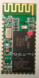
The HC-06 is a bluetooth controller with slave only configuration used to communicate to and from a master Bluetooth module. The master Bluetooth module is capable to initiating a connection with other Bluetooth module, while slave is not able to do that. The slave can only communicate with the master module over a connection established by the master. The HC-06 by default is in slave configuration as per factory settings.
Some of the features of HC-06 which make it apt for the RC car are as follows:
- Can work at the low voltage (3.1V~4.2V). The current in pairing is in the range of 30~40mA. The current in communication is 8mA.
- Has a 2.4GHz digital wireless transceiver.
- Small (27mm×13mm×2mm)
- Peripherals circuit is simple.
- Low power consumption
- Has high-performance wireless transceiver system
- Low Cost
Bluetooth Controller Hardware Design
Master Pin Connections
| Line Item# | Node A Source | Node A Pin | Node B Source | Node B Pin | Description |
|---|---|---|---|---|---|
| 1 | Power Supply | 3.3V | SJOne Board | 3V3 | SJOne Power |
| 2 | Power Supply | GND | SJOne Board | GND | SJOne Ground |
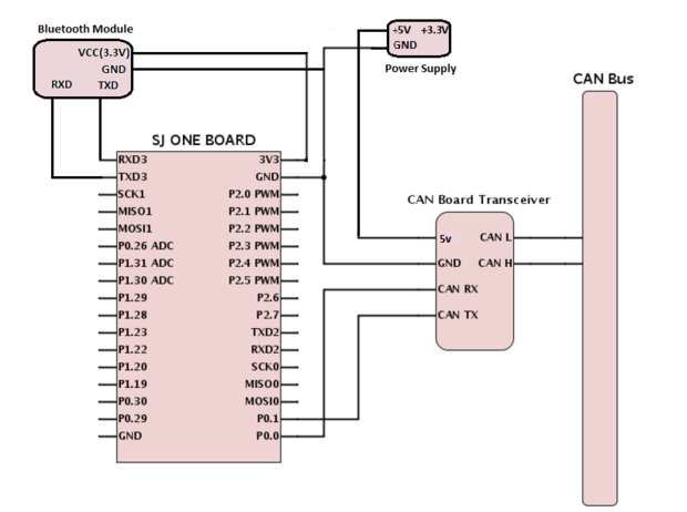
| 3 | CAN Transceiver | CAN Tx | SJOne Board | P0.1 (Tx) | SJOne - CAN Tx |
| 4 | CAN Transceiver | CAN Rx | SJOne Board | P0.0 (Rx) | SJOne - CAN Rx |
| 5 | CAN Transceiver | CAN 5V | Power Supply | 5V | SJOne - CAN Power |
| 6 | CAN Transceiver | CAN Ground | Power Supply | GND | SJOne - CAN Ground |
| 7 | CAN Transceiver | CANL | CAN BUS | CANL | CANL to CAN BUS |
| 8 | CAN Transceiver | CANH | CAN BUS | CANH | CANH to CAN BUS |
| 9 | Bluetooth Module | TXD | SJOne Board | RXD3 | SJOne RX3- Bluetooth module TXD |
| 10 | Bluetooth Module | RXD | SJOne Board | TXD3 | SJOne TX3- Bluetooth module RXD |
| 11 | Bluetooth Module | Bluetooth module VCC(3.3V) | Power Supply | 3.3V | Bluetooth module - Power supply 3.3V |
| 12 | Bluetooth Module | Bluetooth module GND | Power Supply | GND | Bluetooth module - Power supply GND |
Control Flow
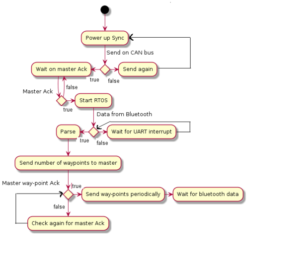
On boot-up, Bluetooth Controller first attempts to sync with the Master controller through a power-up sync and acknowledgement handshake mechanism. Once sync is established with the Master Controller, the Bluetooth controller periodically sends heart-beat signals to master controller till the end of power cycle. If any Bluetooth controller goes out of sync, the master requests the controller to reset itself.
Once all initial handshaking procedures are completed and heart beat signal is established, the Bluetooth Controller waits for data from the On board HC-06 Bluetooth module on the UART port. When Bluetooth connection is established between the Android application and the On board HC-06 Bluetooth controller, routing data is sent from the Android app to the SJOne board. The SJOne board receives the data on UART port via interrupts and parses the data to extract 6 point precision floating point values for each way-points latitude and longitude. The way-point latitude and longitude is stored in a array to be sent out on CAN bus.
Once all way-point data is parsed and ready, the SJOne board first sends out the number of way-points to the master controller and waits for acknowledgement from the master controller. One reception of the acknowledgement from the master and intent to receive the way-point data, the data is sent on the CAN bus periodically till all the data is exhausted.
Communication between Bluetooth and Other Controllers
Power-up Sync and Acknowledgement
Once Bluetooth controller boots up, it continuously sends "Power up Sunc" on the CAN bus to the master using "BLUETOOTH_SYNC_ID" can message id. The controller then polls on the sync function to receive an acknowledgement from the master towards "Power on Sync". Once an acknowledgement is received from master with message id "MASTER_SYNC_ACK_ID", the Bluetooth controller starts the FreeRtos scheduler. Only after this will all tasks run on the controller.
Heart Beat Implementation
Once Bluetooth controller starts the scheduler, it starts sending out heart beat messages on can bus directed towards the master controller using message id "BLUETOOTH_HEARTBEAT_ID" every 1 Hz. If the master does not receive heart beat message it asks Bluetooth controller to reset.
Data Communication
The Bluetooth controller performs data transactions over the CAN bus only with the master controller.
Bluetooth controller signals to the master controller that a new route has been requested from the Android application through “CHECKPOINT_SEND_ID” message id. In this message, the Bluetooth controller also specifies the number of check-points that are present along the route. The Bluetooth Controller waits on master's acknowledgement through “CHECKPOINT_REQ_ID” message id. The Bluetooth controller starts sending the check-points periodically, at 10Hz, after it receives the ack. Once all the way-points are sent to the master, the Bluetooth Controller goes to listening to UART interrupts for any changes in the route.
Flow Chart
The flow chart for the Bluetooth Controller is as follows:
Android App Design
Introduction
The objective of the Android App is to provide the User with an interface that is capable of providing commands to a car. The ubiquity of Android devices, availability of documentation for the Android APIs and Google's comprehensive mapping solution were reasons enough for us to implement this app on the Android platform. With these motivations in mind, the Android app was built with the Google Maps API and the Bluetooth API at its heart.
Design
The design of the app is straightforward- On start up, the user is presented with a Map fragment and buttons that control the behavior of the car. the User has to set his source point and destination point by tapping on two locations on a map. On selecting a destination, the Google Maps Directions API returns a route which is displayed on the Map. The User can then connect to the car and send the route via the buttons in the app.
Implementation
Testing & Technical Challenges
Describe the challenges of your project. What advise would you give yourself or someone else if your project can be started from scratch again? Make a smooth transition to testing section and described what it took to test your project.
Include sub-sections that list out a problem and solution, such as:
Issue #1 (Motor I/O)
The Motor I/O controller is the only controller which accepts all the CAN messages sent on the bus. This is because the LCD needs to print values from the different controllers like Sensor controller, Master controller and Geo controller. It was decided mutually to use the CAN transmit receive function on the bus at same speed, which was 100 Hz. As our controller had to receive more than one frame in one cycle of 10 ms, the hardware CAN rececive queue kept on enlarging. We were dequeueing at a lower speed than expected. So the data received by the software was not fast enough as the data received by the hardware which slowed down our operation. So, a tip for the future, always make sure that you receive the CAN data frame at the same speed as the transmitter's and dequeue your CAN receive queue so as to make sure you are getting all the latest data bytes. We had used while(CAN_RX) condition to keep receiving until we have emptied the queue. And YES! always remove all the printf functions in the periodic scheduler running at 100 HZ frequency or more. This will really help your board not to crash!
Issue #2 (Project Hardware)
We were required to establish CAN communication at an earlier stage itself. In order to do so, we rushed into soldering the CAN bus on the PCB. At a later stage we realized some difficulty as we had soldered the bus in a compact manner. And now, arranging all the LPCs together with all the jumper wirings with the CAN bus truly messed up any debugging that we could do. We had to rearrange the whole hardware and set the arrangements strictly according to the soldered CAN bus which made the task a little unconvenient. TIP - When it comes to hardware, always discuss with your teammates about all the aspects of arranging your car and always keep some space for future use.
Issue #3 (Project Hardware)
Perhaps the most common problem for all the groups, the car crashed at all the initial testing phases. Even if you think your code is perfect and your car will do exactly what you think it will do, it will crash for sure at start and may wreck something here or there(Trying to save your car and not disappoint you!). Install a kill switch at the earliest that will instantly stop the car whenever you want. Atleast implement a kill button in your Mobile App. Also try to cover the front of your car with multiple layers of cardboard, thermocol or a sponge material which will really help the car absorb the shock.
Issue #4 (Geo controller software)
- Geo controller was crashing randomly and that problem was happening because of too much log messages were written to SPI flash memory and memory was full with messages, so we have solved that issue by clearing flash memory and removed unnecessary log messages from the code.
- Initially when we were testing IMU with raw data then it was not giving proper data values so we have calibrated Gyrometer and Magnetometer parameters to get exact angle with precision of +/- 2 degrees, but still as magnetometer's readings were changing with taking any soft/hard iron object near to sensor. So to remove electromagnetic interference generating from DC motor we have put our IMU far from DC Motor.
Issue #5 (Motor Controller software)
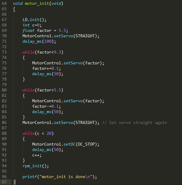
- When we were trying to initialize ESC(Electronic Speed Controller), we didn't know what exact sequence would have to be sent for initialization of DC motor, so we have tried to figure out that thing from Oscilloscope but still somehow we could not able to detect exact sequence of pulses but we hacked the ESC for driving DC motor in Forward and Reverse direction what pulse width is needed and that pulse should be sent in how much frequency. Then to figure out initialization sequence we have done some trial and error case with pre-knowledge of waveforms, we figured out initialization sequence and it was very simple like just we need to send stop motor signal for 1 second and that's it.
- But here main thing was that, give at least 20ms(miliseconds) time to send each pulse proper, otherwise if anyone tries to send pulses less than 20ms then that pwm pulse value can't set properly as DC pwm's frequency was itself 20ms(Frequency - 50Hz).
- And we spent lots of time to figure out this issue and that is, we were trying to have different pwm objects to set DC and Servo motor's pwm values. But we couldn't able to set those values properly. So we thought that our object is destroying somehow so then we tried global pwm objects still we failed, then we tried Static objects still we failed, then finally we made pwm object as Singleton object and problem was solved. So yes applications like this, when we are going to use single channel/resource for different purposes again and again then better to have singleton object of that resource.
Conclusion
Altogether, we really enjoyed being in this class and do this project. We faced many difficulties throughout the semester including understanding the requirements for the project, planning and executing it. But each time we faced a problem, we got to learn many new things. The difficulties led to the deeper knowledge. All of us were stuck at our individual tasks at some point or the other, but we helped each other and finally made our project up and running. Not to mention, Preet was always easily approachable. Our project is running from top to bottom, -> Sending a source, a destination and checkpoints between them from Android app to the Bridge controller -> Sending these co-ordinates to the Geo controller through CAN bus -> Calculating heading and bearing at Geo and giving those back to Master -> Sensor controller sending its reading from sensors in front, sides and back of the car to master -> Deciding where and how much to turn using Geo and Sensor data at Master and sending commands to Motor controller -> Motor I/O controller driving the car and displaying on LCD all the values required for debugging.
Some tasks were very tough to debug. But if you really put your mind into it, you will be able to see the solution right in front of you. One final tip - Do not get frustrated. Always have a bigger picture in mind that what you are getting out of it! We have uploaded everything regarding this project on this page. We honestly appreciate your interest in reading it. Thank you and best of luck!
Project Video
Upload a video of your project and post the link here.
Project Source Code
References
Acknowledgement
We would like to thank Preet for teaching the concepts in a very practical sense in the class. It really helped us in the implementation and the testing of the project. We would also like to thank Rutwik who was always ready to help and who also gave us many ideas of what we can do in the project. All the team members worked really hard towards this project and this motivated us in accomplishing the team goals every week. All in all, a great course which required us not to memorize, but to think in a practical way. Thanks again Preet to introduce this course to the major. This will surely be a major benefit in building our career!
References Used
List any references used in project.
[1] Preetpal Kang's lecture notes of CMPE 243, Computer Engineering, San Jose State University, Aug-Dec 2015.
[2] Wiki Projects
[3] LPC17XX datasheet
[4] Parallax Ultrasonic Sensor
[5] CAN Transceiver
[6] Razor IMU
[7] Adafruit Ultimate GPS Breakout - 66 channel w/10 Hz updates - Version 3
[8] GPS data calculation accuracy
[9] GPS Longitude Latitude distance calculator
[10] Calculate distance between two points
[11] GLCD with Touchscreen
[12] HCSR04 Ultrasonic Sensor
Appendix
You can list the references you used.
