S15: Multi-media Car
Contents
Grading Criteria
- How well is Software & Hardware Design described?
- How well can this report be used to reproduce this project?
- Code Quality
- Overall Report Quality:
- Software Block Diagrams
- Hardware Block Diagrams
- Schematic Quality
- Quality of technical challenges and solutions adopted.
Multi-media Car
Abstract
The aim of this project is to build a self-driving car which can automatically avoid big barriers and obstacles in its path.
Objectives & Introduction
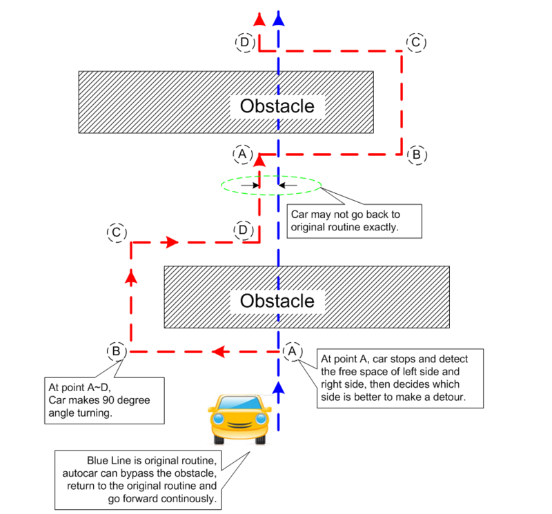
The final object of our project is designing a car not only can avoid the obstacles, but also can find its own path after the detour.
1. Avoiding the obstacles in front of the car.
2. The car can decide to whether turn left or right or reverse by measuring the obstacles on left and right side.
3. After making a successful turning, the car should find its original orientation then get back to its previous path.
The car should work as the following picture.
Team Members & Responsibilities
- Zan Zhan
- <role>
- Rohit Teja Maddula
- <role>
- Mengchi Cheng
- <role>
- Taowu Wen
- <role>
Schedule
| Week No. | Start Date | Planned End Date | Task | Status | Actual Completion Date |
|---|---|---|---|---|---|
| 1 | 04/06/2015 | 04/12/2015 | Interfacing motors with SJone board, building the power circuit design | Completed | 04/12/2015 |
| 2 | 04/13/2015 | 04/19/2015 | Interfacing infrared sensor and ultrasonic sensor, using the feedbacks to control the motors. | Completed | 04/19/2015 |
| 3 | 04/20/2015 | 04/26/2015 | Writing functions of motors(including turn left&right&forward&revesre), verify the accuracies of those functions. | Completed | 04/28/2015 |
| 4 | 04/27/2015 | 05/03/2015 | Implementing three ultrasonic sensors, and using the feedbacks to achieve the car can automatically find its own path when counter obstacles. | completed | 05/03/2015 |
| 5 | 05/04/2015 | 05/10/2015 | Depending on the previous function, adjusting the motors control module to ensure the car keep going straight in the case of no obstacles. | Ongoing | N/A |
| 6 | 05/11/2015 | 05/17/2015 | Assemble all the features together, use multi-tasking to connect all equipment as a unity. | completed | 05/18/2015 |
| 7 | 05/18/2015 | 05/23/2015 | Check all the details, updating Wiki. | completed | 05/24/2015 |
Parts List & Cost
Give a simple list of the cost of your project broken down by components. Do not write long stories here.
| Part No. | Part Type | Part Description | Quantity | Cost for each | Total |
|---|---|---|---|---|---|
| 1 | 28015-ND | Ultrasonic Distance Sensor | 3 | $ 2.20 | $ 6.60 |
| 2 | L298N | Motor drive controller board | 1 | $ 8.50 | $ 8.50 |
| 3 | LTYKC-01 | DIY Toy Car (Including 2 DC motors) | 1 | $ 7.00 | $ 7.00 |
| 4 | MN1500 | Batteries(1.5V/each) | 10 | $ 1.00 | $ 10.00 |
| 5 | FC-51 | Infrared Sensor | 1 | $ 3.00 | $ 3.00 |
| 6 | SJOne Board | Board including LPC1758 from SJSU CmpE | 1 | $ 80.00 | $ 80.00 |
| Total Cost | $ 115.10 |
Design & Implementation
The design section can go over your hardware and software design. Organize this section using sub-sections that go over your design and implementation.
Hardware Design
Infrared Sensor
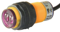
The infrared sensor has three wires: power, GND and feedback. Power is supplied by the SJone board, and it has a common GND with SJone Board. Feedback remains high if there are no obstacles, whenever the car encounter some obstacles, it will drop to logic low. Thus, by detecting the falling edge of the feedback PIN, we can use the infrared sensor to stop our car immedetately.
Ultrasonic Sensor
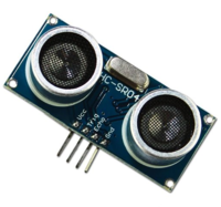
The Ultrasonic sensor is powered by the H-bridge which has a +5V power supply. In the detecting task, three ultrasonic are trigged by the pulses that are sent by SJone Board. After receiving the pulses, the ultrasonic sensor will produce a period of logic high on its echo PIN. By detecting the length of this feedback signals, we can calculate the distance between the obstacles and our car.
H-bridge
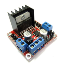
H-bridge is used to control the motor and communicates with SJone Board. When the power supply of H-bridge is between 7-12V, one of its pin can be use as a 5V power supply. H-bridge has two sets of GPIOs to control different motors. Each set has two GIPOs, one for moving forward, another one is reversing.
Schematic
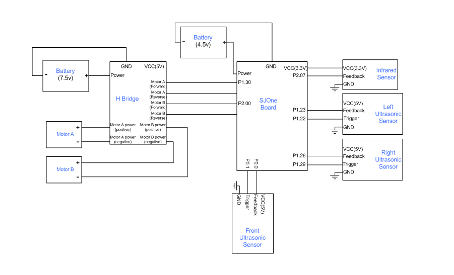
This is the overall schematic for our design.
Hardware Interface
- Power circuit is a series of batteries, which provides 7.5V power supply.
- SJone Board is communicating with different sensors. Including sending trigger signals to ultrasonic sensors and getting feedbacks of those sensors.
- Infrared sensor is used to detect any obstacles in front of the car.
- Ultrasonic sensors are triggered by the high pulse sending by SJone Board and gives the feedback back. We can get the distances between obstacles and the car by calculating the length of those feedbacks.
| PIN No. | PIN type | Ussage |
|---|---|---|
| P0.00 | GPIO | Sending trigger signals to front ultrasonic sensor |
| P0.10 | GPIO | Getting the feedback from front ultrasonic sensor |
| P1.22 | GPIO | Sending trigger signals to left ultrasonic sensor |
| P1.23 | GPIO | Getting the feedback from left ultrasonic sensor |
| P1.28 | GPIO | Sending trigger signals to right ultrasonic sensor |
| P1.29 | GPIO | Getting the feedback from right ultrasonic sensor |
| P1.30 | GPIO | Motor B moves forward |
| P2.00 | GPIO | Motor A moves forward |
| P2.07 | GPIO | Getting the feedback from infrared sensor |
Software Design
- Creating interrupt functions for the infrared sensor.
- Creating different tasks for controlling the motor movement(such as stop, forward and turn left).
- Using semaphores to switch between different tasks.
- Creating those tasks and semaphores in main() and initiating several sensors.
Infrared Interrupt
The infrared interrupt is only enabled in the Run_forward task. Whenever the car meets any obstruction while moving forward, the interrupt will hang on the current task and change to different emergency task depending on the DIR flag. If the DIR flag is 0, which means the car haven't made any turn, the interrupt task will send an item to the turning queue. If the DIR flag is not 0, which means the car already made the turnings but the path is blocked by an unpredicted obstacle, the car will stop immediately until the obstacle disappear.
Implementation
This section includes implementation, but again, not the details, just the high level. For example, you can list the steps it takes to communicate over a sensor, or the steps needed to write a page of memory onto SPI Flash. You can include sub-sections for each of your component implementation.
Testing & Technical Challenges
Describe the challenges of your project. What advise would you give yourself or someone else if your project can be started from scratch again? Make a smooth transition to testing section and described what it took to test your project.
Include sub-sections that list out a problem and solution, such as:
My Issue #1
- Controlling the car to move straight forward
In order the find the original path, our design is required to follow the expected path. However, due to the deficiency of our motor and the unsmooth of the ground, the car cannot go straight forward.
solution
Conclusion
Conclude your project here. You can recap your testing and problems. You should address the "so what" part here to indicate what you ultimately learnt from this project. How has this project increased your knowledge?
Project Video
Upload a video of your project and post the link here.
Project Source Code
References
Acknowledgement
Any acknowledgement that you may wish to provide can be included here.
References Used
List any references used in project.
Appendix
You can list the references you used.
