S15: Hovercopter
Contents
- 1 Grading Criteria
- 2 Hovercopter
- 3 Abstract
- 4 Introduction
- 4.1 Objectives
- 4.2 Schedule
- 4.3 Parts List & Cost
- 4.4 Design & Implementation
- 4.5 Testing & Technical Challenges
- 4.6 Conclusion
- 4.7 References
Grading Criteria
- How well is Software & Hardware Design described?
- How well can this report be used to reproduce this project?
- Code Quality
- Overall Report Quality:
- Software Block Diagrams
- Hardware Block Diagrams
- Schematic Quality
- Quality of technical challenges and solutions adopted.
Hovercopter
Abstract
The goal of our project is to design a quadcopter that is capable of self-stabilizing with altitude holding capabilities. The software will use a PID control algorithm to stabilize the motor speeds according to the accelerometer and gyroscope sensor values. The hardware will consist of interfacing the SJSU One board with an Adafruit 10-DOF sensor, remote control receiver, five sonar sensors, an electronic speed controller (ESC), and the four motors. The quadcopter will be able to avoid obstacles using the sonar sensors.
Introduction
Show list of your objectives. This section includes the high level details of your project. You can write about the various sensors or peripherals you used to get your project completed.
Objectives
Our objectives include the following:
- Self-balancing and self-stabilizing system with the ability to pitch forward, pitch backward, roll left, roll right, yaw left, and yaw right.
- Altitude hold with the use of a sonar sensor and obstacle avoidance with the use of 4 sonar sensors.
- Clear unobstructed communication from the remote control transmitter to the remote control receiver located on the system.
- Arm/Disarm
- Kill switch
- SD Card logging
Team Members & Responsibilities
- Arlen Eskandari
- Jonathon Hongpananon
- Phillip Tran
Schedule
Show a simple table or figures that show your scheduled as planned before you started working on the project. Then in another table column, write down the actual schedule so that readers can see the planned vs. actual goals. The point of the schedule is for readers to assess how to pace themselves if they are doing a similar project.
| Week# | Start Date | End Date | Task | Status | Actual Completion Date |
|---|---|---|---|---|---|
| 1 | 4/14/2015 | 4/20/2015 | Correctly route North, South, East, and West pins to their respective motor/ESC wire locations. Start testing and determining a proper P value, then I, then D value. | As of 4/20/15, we have wired the correct NSEW pins to their respective ESC wires. We are still determining a proper Proportional value. | 4/20/15 |
| 2 | 4/21/2015 | 4/27/2015 | Continuation of determining Proportional, Integral, and Derivative values. | As of 4/30/15, we have stabilization but it still needs minor tuning for correct P, I, and D values. It appears to wobble occasionally during maneuvering so we will continue working on tuning before going any further with the next task. | 4/30/15 |
| 3 | 4/28/2015 | 5/4/2015 | Install sonar sensors for future altitude holding. Use pid tune task which iterates through a range of selected P, I, and D values. This will log the PID output with the respective PID values onto the SD card. We will use Excel to graph the output to determine the smoothest curve with no overdamp/underdamp effect. | Complete | 5/7/15 |
| 4 | 5/5/2015 | 5/11/2015 | Continuation of PID fine Tuning | Ongoing | N/A |
| 5 | 5/12/2015 | 5/18/2015 | Fix gyroscope sensor readings and tune PID values for yawThrottle. | Complete | 5/15/15 |
| 6 | 5/19/2015 | 5/22/2015 | Test complete movement consisting of pitch forward, pitch backward, roll right, and roll left. | Ongoing | N/A |
Parts List & Cost
Give a simple list of the cost of your project broken down by components. Do not write long stories here.
| Qty | Description | Manufacturer | Part Number | Total Cost |
|---|---|---|---|---|
| 1 | FPV 4-Axis Quadcopter Frame kit w/ Protective Guard | UFO | $41.00 | |
| 1 | Brushless 25A SimonK 4-in-1 ESC Built-in UBEC | Emax | 24A*4-UBEC | $29.00 |
| 4 | 6045 Carbon Nylon Propellers | Gemfan | $4.00 | |
| 1 | SJOne Board | Preet | LPC1758 SJSU Board | $80.00 |
| 1 | 9X 9ch Transmitter w/ Module & 8ch Receiver | Turnigy | TX-9X-M2 | $60.00 |
| 1 | x2204 2300kv Brushless Motors - set of 4 | SunnySky | SNS-X2204S-KV2300 | $63.00 |
| 2 | 4000mAh 3S 30C Lipo Battery Pack | Turnigy | T4000.3S.30 | $22.00 |
| 1 | 50W 5A Balancer Charger | Hobbyking | ECO6 | $19.00 |
| 1 | 4-mm to XT-60 Battery Adaptors - set of 2 | Turnigy | XT60-HXT4MM | $3.00 |
| 1 | 105W 15V/7A DC power supply | Hobbyking | 9052000023-3 | $15.00 |
| 1 | 3.5mm Gold Connectors | Polymax | $2.00 | |
| 1 | Short Nylon Threaded Spacers | $8.00 | ||
| 1 | Long Nylon Threaded Spacers | $6.00 | ||
| 1 | Test Environment Frame for testing | Home Depot | $15.00 | |
| Total Cost (excluding shipping and taxes) | $367.00 |
Design & Implementation
The design section can go over your hardware and software design. Organize this section using sub-sections that go over your design and implementation.
Hardware Design
Discuss your hardware design here. Show detailed schematics, and the interface here.
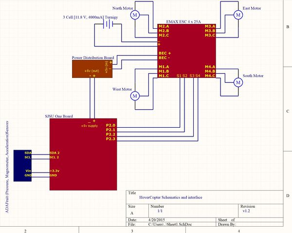
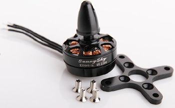
To make the quadcopter a SJOne board is used on which the flight controller software is developed. This board reads the sensors values and generates the PWM (Pulse Width Modulation) pulses to drive the four motors. In this project four KV2300 Sunnysky brushless servo motors are used. 2300KV means that for each one volt applied to the motor it will produce an RPM of 2300. The battery used in this project is 3cell 11.8V which roughly produces 27k rpm. Each of the motors are capable of lifting 500 grams on full throttle.
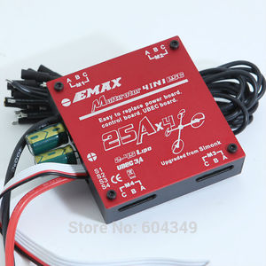
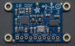
These motors are very fast so they draw a lot of current which can’t be provided by SJOne board, so too make the motors to spin the output of the SJOne board is fed into an ESC (Electronic Speed Controller). The EMAX ESC used is capabale of delivering 25 Amperes of continuous current for each motor. Wires to connect the motors to the ESC are 18AWG to be able to support the high current that motors are drawing. The battery is directly connected to the ESC which is used to power the four motors and part of it is also regulated to 5Volts which is used as the power source for other on board electronic systems. A separate power distribution board is designed which provides both 5 and 3.3 volts. The ADAFruit sensor board, along with five sonar sensors, and the remote control receiver which operate with 3.3 Volts receive their supply voltage from this board. The SJSU one board is also connected to this board for its 5Volt supply voltage.
A UFO frame with propellers guard (figure xx) is used for this project. This frame is mainly chosen for safety reasons since the propellers spin very fast and can be dangerous. The ADAFruit sensor board uses the I^2 C bus, so it is connected to SDA2 and SCL2 signals of SJOne board. The remote control receiver is connected to the GPIO pins as follows:
P0.0 RC-Ch1 – Pitch (Ch2. of RC receiver - Grey wire)
P0.1 RC-Ch2 - Roll (Ch1. of RC receiver - White wire)
P0.29 RC-Ch3 - Yaw (Ch4. of RC receiver - Orange wire)
P0.30 RC-Ch4 - Throttle (Ch3. of RC receiver - Yellow wire)
P2.6 RC-Ch5 - Arm/Disarm Gear Switch on RC Remote
The four motors are connected to the PWM enabled GPIO ports of the SJOne board in following order:
P2.0 North Motor
P2.1 South Motor
P2.2 East Motor5
P2.3 West Motor
Remote Control Transmitter & Receiver
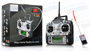
The remote control transmitter is responsible for transmitting the desired throttle, pitch, roll, and yaw angles. We chose the FlySky FS-T6 model, which has 6 available channels. The operating frequency is 2.4GHz and the remote comes with many features including a backlit LCD. The channels and their associated operation are :
Channel 1 - Pitch
Channel 2 - Roll
Channel 3 - Throttle
Channel 4 - Yaw
Channel 5 - N/A
Channel 6 - Arm/Disarm
Motors
Brushless motors are perfect for quadcopters because of their superior efficiency. They are much more powerful than conventional brushed motors and less electrical energy is wasted. The fewer mechanical parts result in reduced operational noise and quieter performance. Brushless motors work by producing magnetic fields to produce electric charges. Magnets will attempt to align, thus, causing the motor to spin. A continuous flow on multiple magnets will result in constant spinning depending on the signals sent to the device. Different currents are flowing through different coils making the motor shaft spin. The speed of the spinning motor shaft is controlled by an ESC (electronic speed controller) and is performed by switching the motor coils on or off rapidly at different, but synchronized, times.
Electronic Speed Controller (ESC)
INSERT INFORMATION ABOUT ESC HERE
IMU Sensor
INSERT INFORMATION ABOUT ADAFRUIT IMU SENSOR HERE
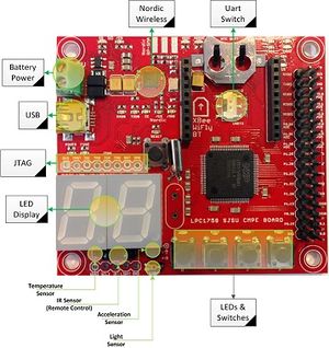
SJOne Flight Controller
INSERT INFORMATION ABOUT A FLIGHT CONTROLLER HERE
Hardware Interface
In this section, you can describe how your hardware communicates, such as which BUSes used. You can discuss your driver implementation here, such that the Software Design section is isolated to talk about high level workings rather than inner working of your project.
Communication protocols used :
 UART - Serial communication and telemetry.
 PWM (Pulse Width Modulation) - Decoding remote control signals into pulse signals the ESC's can use to drive the motors
 Interrupts - Usage of the GPIO ports on the SJSU One board and the timer API to capture the PPM signals from the remote control transmitter to receiver.
Software Design
Our software utilizes object oriented programming (OOP) concepts. There are many types of "objects" which hold data in our system. For example, mFlightControllerAngles holds the current setpoint angles for all axis, mCurrentAngles holds the current x, y, and z-axis angles, and mMotorValues holds the motor values which will be applied to the motors. There are several different classes which separate the different functions in the system. The lowest level class, MotorControllerIface is an abstract class which contains undefined virtual methods. These virtual methods are defined in inherited classes which will use them. The FlightStabilizer class is responsible for controlling flight parameters using the sensor data and controlling lower-level flight logic. The highest level class, QuadcopterBase, is defined for high-level flight logic such as autonomous GPS flying.
PID Controller
INSERT INFO ABOUT PID CONTROL HERE
Implementation
This section includes implementation, but again, not the details, just the high level. For example, you can list the steps it takes to communicate over a sensor, or the steps needed to write a page of memory onto SPI Flash. You can include sub-sections for each of your component implementation.
System Initialization
- Get the sensor inputs
- Update the flight sensor system data
- Update flying logic
- Run PID loop
- If timing is skewed, light up LED and increment TimingSkewedCount.
- If armed, apply motor values. Otherwise, apply value 0 to motors.
Remote Control Signal Decoding
- Initialize ports for interrupt on rising and falling edges of inputs.
- On rising edge of signal, start timer capture.
- On falling edge of signal, stop timer capture.
- Pulse width = stop - start
- Decode pulse width signals to normalized values: 0->100 for throttle, and -45->+45 for pitch, roll, and yaw.
- Set values to flight parameters - flightParams_t.
Testing & Technical Challenges
Issue #1
Issue: We first had inconsistent motor/propeller spinning. They were not spinning with normal behavior so we traced it back to the values that are applied to the motor from the remote control signals. The values decoded from the remote controls signals were incorrect. The ESC"s accept PWM servo pulses upon calibration and we initially had the SJSU One board outputting PWM duty cycle signals to the ESC. We reworked the remote control decoding functions to correct PWM pulses ranging from 1ms to 2ms wide pulses.
Result: The result was smooth operation of motors/propellers when throttle was applied from the remote control to the SJSU One board.
Issue #2
Issue: During the week of 4/24/15 to 4/29/15, we had remote control transmitter issues. It started out with random spikes in throttle pulse widths. We fixed the random spikes by adding control in our software, but eventually the throttle had no response. Change in the joystick would have no effect on the actual pulse width received from the receiver.
Result: Our solution was to order a different brand, especially not the Turnigy 9x. We opted for the FlySky FS-T6 remote control transmitter. So far, it has better response, light up display, and ability to adjust throttle curve which the Turnigy didn't have.
Conclusion
Conclude your project here. You can recap your testing and problems. You should address the "so what" part here to indicate what you ultimately learnt from this project. How has this project increased your knowledge?
Project Video
Initial testing of P values : https://www.youtube.com/watch?v=IqSVVo5YJBs&feature=youtu.be
Second stage of testing with P, I, and D values : https://www.youtube.com/watch?v=PpRCZm-XeGI
Project Source Code
References
Acknowledgement
Any acknowledgement that you may wish to provide can be included here.
References Used
http://www.rctoys.com/pr/2009/05/25/all-about-brushless-motors-what-you-need-to-know/
Appendix
You can list the references you used.
